Search results for "Resistor

The 1µF 50V electrolytic capacitor is a polarized electronic component used for storing and releasing electrical energy. Electrolytic capacitors are known for their high capacitance values and are commonly used in power supply filtering, decoupling, and coupling applications. This capacitor is suitable for various electronic circuits, including audio, power management, and signal processing.

Key Features:

  • Capacitance: 1µF
  • Voltage Rating: 50V
  • High capacitance value relative to physical size
  • Polarized (has positive and negative leads)
  • Long service life with high reliability
  • Suitable for high-frequency applications

Technical Specifications:

  • Capacitance: 1µF
  • Voltage Rating: 50V
  • Tolerance: ±20% (typical for electrolytic capacitors)
  • Operating Temperature Range: -40°C to +85°C
  • ESR (Equivalent Series Resistance): Varies (check manufacturer specifications)
  • Leakage Current: Varies (check manufacturer specifications)
  • Dimensions: Varies (typically around 5mm diameter x 11mm height for through-hole packages)
  • Lead Spacing: Varies (typically around 2mm to 5mm for through-hole packages)

Applications:

  • Power Supply Filtering: Smooths out voltage fluctuations in power supply circuits.
  • Decoupling: Reduces noise and stabilizes voltage in electronic circuits.
  • Coupling: Transfers signals between different parts of a circuit without transferring DC voltage.
  • Timing Circuits: Used in combination with resistors to create timing circuits.
  • Audio Circuits: Used in audio signal processing and amplification.

Usage:

  1. Identify the correct polarity of the capacitor (positive and negative leads).
  2. Solder the capacitor onto the PCB, ensuring correct orientation.
  3. Verify the capacitor’s voltage rating and capacitance match the circuit requirements.
  4. Test the circuit to ensure the capacitor is functioning as expected.

Caution:

  • Ensure correct polarity when connecting the capacitor to avoid damage or failure.
  • Do not exceed the voltage rating of the capacitor to prevent damage.
  • Handle with care to avoid physical damage to the capacitor.
  • Store in a dry, cool place to maintain the integrity and reliability of the capacitor.

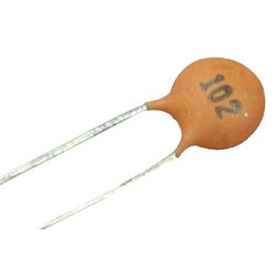
The 102 ceramic capacitor is a small, non-polarized capacitor with a capacitance value of 0.001µF (1nF or 1000pF). Ceramic capacitors are known for their stability, reliability, and low cost. They are commonly used in various electronic circuits for applications such as filtering, bypassing, coupling, and decoupling.

Key Features:

  • Capacitance: 0.001µF (1nF or 1000pF)
  • Voltage Rating: Varies (typically 50V, 100V, or higher)
  • Non-polarized (can be connected in either direction)
  • Stable and reliable performance
  • Low cost
  • Wide temperature range

Technical Specifications:

  • Capacitance: 0.001µF (1nF or 1000pF)
  • Voltage Rating: Typically 50V, 100V, or higher (check specific part number for exact rating)
  • Tolerance: ±5%, ±10%, ±20% (varies by manufacturer and specific part)
  • Temperature Coefficient: Varies (typically NPO/C0G, X7R, or Y5V)
  • Operating Temperature Range: -55°C to +125°C (varies by specific part and material)
  • Dimensions: Varies by package type (e.g., 0603, 0805, radial, or axial leads)
  • Lead Spacing: Varies by package type

Applications:

  • Filtering: Removes unwanted noise from signals in power supplies and signal lines.
  • Bypassing: Provides a low impedance path to ground for AC signals.
  • Coupling: Passes AC signals between different stages of an amplifier without passing DC.
  • Decoupling: Stabilizes voltage supply by reducing voltage spikes and noise.
  • Timing Circuits: Works with resistors to create RC time constants in timing applications.
  • Oscillators: Used in frequency-determining networks for oscillators.

Usage:

  1. Determine the required capacitance and voltage rating for your circuit.
  2. Place the capacitor in the correct position on the PCB.
  3. Solder the capacitor in place, ensuring good contact and avoiding excess heat.
  4. Verify the capacitor’s connections and ensure no short circuits.

Caution:

  • Verify the voltage rating and capacitance before use.
  • Handle carefully to avoid physical damage to the capacitor.
  • Ensure the capacitor is not exposed to excessive heat during soldering.
  • Store in a dry, cool place to maintain the integrity of the capacitor.

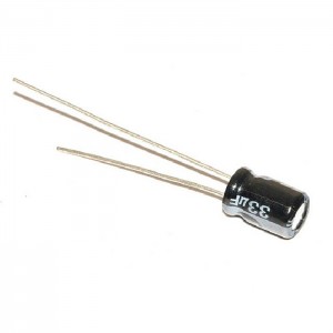
The 33µF 25V electrolytic capacitor is a polarized capacitor that offers a high capacitance value in a relatively small package. Electrolytic capacitors are widely used in power supply circuits, audio applications, and various other electronic devices due to their ability to store and release energy efficiently.

Key Features:

  • Capacitance: 33µF
  • Voltage Rating: 25V
  • Polarized (positive and negative leads)
  • High capacitance-to-volume ratio
  • Suitable for power supply filtering and energy storage
  • Long lifespan and reliable performance

Technical Specifications:

  • Capacitance: 33µF
  • Voltage Rating: 25V
  • Tolerance: ±20% (typical)
  • Operating Temperature Range: -40°C to +85°C (varies by specific part)
  • ESR (Equivalent Series Resistance): Low (varies by specific part)
  • Leakage Current: ≤ [specified by manufacturer, typically in microamperes]
  • Dimensions: Varies by manufacturer and specific part number
  • Lead Spacing: Varies by manufacturer and specific part number

Applications:

  • Power Supply Filtering: Smooths out voltage fluctuations and reduces ripple.
  • Decoupling: Stabilizes voltage supply by reducing voltage spikes and noise.
  • Energy Storage: Provides energy storage in power supplies and converters.
  • Audio Applications: Used in audio circuits for coupling and decoupling.
  • Timing Circuits: Works with resistors to create RC time constants in timing applications.

Usage:

  1. Determine the required capacitance and voltage rating for your circuit.
  2. Identify the positive and negative leads of the capacitor (the longer lead is typically positive).
  3. Place the capacitor in the correct position on the PCB, ensuring proper polarity.
  4. Solder the capacitor in place, ensuring good contact and avoiding excess heat.
  5. Verify the capacitor’s connections and ensure no short circuits.

Caution:

  • Ensure proper polarity during installation to avoid damage.
  • Verify the voltage rating and capacitance before use.
  • Handle carefully to avoid physical damage to the capacitor.
  • Ensure the capacitor is not exposed to excessive heat during soldering.
  • Store in a dry, cool place to maintain the integrity of the capacitor.
Datasheet:
For detailed technical specifications, refer to the specific electrolytic capacitor model’s datasheet from the manufacturer.


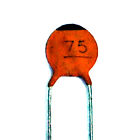
The 75pF capacitor is a small-value capacitor typically used in RF (radio frequency) and high-frequency applications, such as tuning circuits, filters, and oscillators. These capacitors are generally non-polarized and come in various types like ceramic, mica, or film, offering stability and low losses at high frequencies.

Key Features:

  • Capacitance: 75pF
  • High-frequency performance
  • Low Equivalent Series Resistance (ESR)
  • Stable capacitance over temperature and frequency
  • Available in various types (ceramic, mica, film)
  • Non-polarized

Technical Specifications:

  • Capacitance: 75pF
  • Voltage Rating: Varies (commonly 50V, 100V, 500V, or higher)
  • Tolerance: ±1%, ±2%, ±5%, or ±10% (depending on type)
  • Temperature Coefficient: Varies by type (e.g., C0G/NP0 for ceramic capacitors)
  • ESR: Low (varies by type and manufacturer)
  • Operating Temperature Range: -55°C to +125°C (varies by type)
  • Package Type: Through-hole or Surface-mount (varies by type)

Applications:

  • RF Circuits: Used for tuning, filtering, and impedance matching in radio frequency applications.
  • Oscillators: Helps stabilize the frequency in oscillator circuits.
  • Filters: Used in high-frequency filters for signal processing.
  • Coupling and Decoupling: Provides coupling and decoupling in high-frequency circuits.
  • Timing Circuits: Works with inductors or resistors to create timing elements in high-frequency circuits.

Usage:

  1. Determine the required capacitance and voltage rating for your circuit.
  2. Select the appropriate capacitor type based on application requirements (e.g., ceramic for stability, mica for precision).
  3. Identify the capacitor’s leads or pads for correct placement on the PCB.
  4. Solder the capacitor in place, ensuring good contact and avoiding excessive heat.
  5. Verify the capacitor’s connections and ensure no short circuits.

Caution:

  • Verify the capacitance and voltage rating before use.
  • Handle carefully to avoid damage to the capacitor body and leads.
  • Ensure the capacitor is not exposed to excessive heat during soldering.
  • Store in a dry, cool place to maintain the integrity of the capacitor.
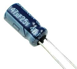
The 47µF 25V electrolytic capacitor is a versatile passive electronic component commonly used in power supplies, signal processing circuits, and various electronic devices. This capacitor is ideal for applications requiring energy storage, filtering, and decoupling due to its high capacitance and voltage rating. Its polarized design, with aluminum foil as the anode and an electrolytic solution as the cathode, allows for a compact and efficient solution.

Key Features:

  • Capacitance: 47µF
  • Voltage Rating: 25V
  • Polarized (anode and cathode)
  • High capacitance in a compact size
  • Suitable for high-frequency applications
  • Long life and high reliability
  • Stable performance over a wide temperature range

Technical Specifications:

  • Capacitance: 47µF
  • Voltage Rating: 25V
  • Tolerance: ±20%
  • Operating Temperature Range: -40°C to +105°C
  • Leakage Current: ≤ 0.01CV or 3µA (whichever is greater) after 2 minutes at 25°C
  • Equivalent Series Resistance (ESR): Typically low, varies by manufacturer
  • Dimensions: Varies by manufacturer and specific model
  • Lead Type: Radial or axial, depending on design

Applications:

  • Power Supply Filtering: Smooths out voltage fluctuations in power supplies.
  • Decoupling: Reduces noise in power lines and stabilizes voltage.
  • Timing Circuits: Used in conjunction with resistors to create RC timing circuits.
  • Energy Storage: Provides energy storage in various electronic circuits.
  • Signal Coupling and Bypassing: Couples AC signals between stages of amplifiers and bypasses AC noise.

Usage:

  1. Determine the required capacitance and voltage rating for your circuit.
  2. Identify the positive (longer lead) and negative (shorter lead, marked with a stripe) terminals of the capacitor.
  3. Insert the capacitor into the circuit, ensuring correct polarity.
  4. Solder the leads in place, ensuring good contact and avoiding excessive heat.
  5. Verify the capacitor’s connections and ensure no short circuits.

Caution:

  • Verify the capacitance and voltage rating before use.
  • Ensure correct polarity when connecting the capacitor to prevent damage or failure.
  • Handle carefully to avoid damage to the capacitor body and leads.
  • Store in a dry, cool place to maintain the integrity of the capacitor.
  • Avoid exposing the capacitor to temperatures beyond its rated range.

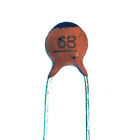
The 68pF capacitor is a small, fixed-value capacitor widely used in electronic circuits for tasks such as tuning, coupling, and decoupling. Its small capacitance value makes it suitable for high-frequency applications and precise timing circuits. It can be found in various packages, including ceramic, film, or mica, depending on the application requirements.

Key Features:

  • Capacitance: 68pF
  • Low capacitance value for high-frequency applications
  • Stable performance over a wide temperature range
  • Available in various dielectric materials (ceramic, film, mica)
  • Suitable for surface-mount or through-hole applications
  • Low equivalent series resistance (ESR)
  • High stability and reliability

Technical Specifications:

  • Capacitance: 68pF
  • Voltage Rating: Typically ranges from 50V to 500V, depending on the type
  • Tolerance: ±5% to ±10%, depending on the specific model
  • Temperature Coefficient: Varies by dielectric material (e.g., C0G/NP0 for ceramic capacitors)
  • Operating Temperature Range: -55°C to +125°C, depending on the type
  • Dielectric Material: Ceramic, film, or mica
  • Package Type: Available in SMD (surface-mount device) or through-hole

Applications:

  • RF and Microwave Circuits: Used in tuning and matching networks.
  • Oscillators: Helps stabilize frequency in oscillator circuits.
  • Filters: Forms part of high-frequency filters.
  • Coupling and Decoupling: Isolates AC signals between different stages of a circuit.
  • Timing Circuits: Provides precise timing in conjunction with resistors.

Usage:

  1. Determine the required capacitance value and voltage rating for your circuit.
  2. Identify the appropriate package type (SMD or through-hole) for your application.
  3. Insert the capacitor into the circuit, ensuring correct placement according to the schematic.
  4. Solder the leads or pads in place, ensuring good contact and avoiding excessive heat.
  5. Verify the capacitor’s connections and ensure no short circuits.

Caution:

  • Verify the capacitance and voltage rating before use.
  • Handle with care to avoid damage to the capacitor body and leads.
  • Store in a dry, cool place to maintain the integrity of the capacitor.
  • Avoid exposing the capacitor to temperatures beyond its rated range.
  • Ensure proper orientation in the circuit, especially for polarized capacitors (though most 68pF capacitors are non-polarized).

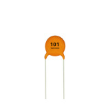
The 101 ceramic capacitor, also known as a 100pF capacitor, is a versatile and reliable passive electronic component. It is primarily used for filtering, coupling, and decoupling applications in a wide range of electronic circuits. Its small capacitance value and stable performance make it ideal for high-frequency applications, such as RF circuits and signal processing.

Key Features:

  • Capacitance: 100pF
  • Stable performance over a wide frequency range
  • Low equivalent series resistance (ESR)
  • High reliability and long lifespan
  • Available in various package types (through-hole and SMD)
  • Suitable for high-frequency applications
  • Low loss and high Q factor

Technical Specifications:

  • Capacitance: 100pF (0.0001uF, 0.1nF)
  • Voltage Rating: Typically 50V to 500V, depending on the specific model
  • Tolerance: ±5% to ±10%, depending on the manufacturer
  • Temperature Coefficient: Varies by dielectric material (e.g., C0G/NP0 for stable performance)
  • Operating Temperature Range: -55°C to +125°C
  • Dielectric Material: Ceramic (often C0G/NP0 or X7R)
  • Package Type: Available in through-hole and surface-mount device (SMD)

Applications:

  • High-Frequency Filtering: Used in RF circuits for signal filtering and tuning.
  • Coupling and Decoupling: Isolates AC signals and filters noise in power supply lines.
  • Oscillators: Provides frequency stability in oscillator circuits.
  • Timing Circuits: Used in conjunction with resistors for precise timing applications.
  • Signal Processing: Helps in the conditioning and processing of analog signals.

Usage:

  1. Identify the required capacitance value and voltage rating for your application.
  2. Select the appropriate package type (through-hole or SMD) for your circuit.
  3. Place the capacitor in the designated location on the circuit board, ensuring correct orientation if applicable.
  4. Solder the capacitor leads or pads in place, using proper soldering techniques to avoid damage.
  5. Inspect the connections to ensure a secure and reliable installation.

Caution:

  • Verify the capacitance and voltage rating before use to avoid circuit damage.
  • Handle with care to prevent physical damage to the capacitor body and leads.
  • Store in a cool, dry place to maintain capacitor integrity.
  • Ensure proper orientation in polarized applications (though most 100pF ceramic capacitors are non-polarized).
  • Avoid exceeding the rated voltage and temperature limits.

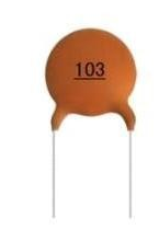
The 103 ceramic capacitor, also known as a 0.01uF capacitor, is a versatile passive electronic component commonly used for filtering, coupling, and bypass applications. Its moderate capacitance value and stable performance make it suitable for various electronic circuits, including analog and digital applications.

Key Features:

  • Capacitance: 0.01uF (10nF, 10000pF)
  • Stable performance over a wide frequency range
  • Low equivalent series resistance (ESR)
  • High reliability and long lifespan
  • Available in various package types (through-hole and SMD)
  • Suitable for decoupling and noise filtering
  • Low loss and high Q factor

Technical Specifications:

  • Capacitance: 0.01uF (10nF, 10000pF)
  • Voltage Rating: Typically 50V to 500V, depending on the specific model
  • Tolerance: ±5% to ±10%, depending on the manufacturer
  • Temperature Coefficient: Varies by dielectric material (e.g., C0G/NP0 for stable performance)
  • Operating Temperature Range: -55°C to +125°C
  • Dielectric Material: Ceramic (often C0G/NP0 or X7R)
  • Package Type: Available in through-hole and surface-mount device (SMD)

Applications:

  • Filtering: Used to filter noise and smooth signals in power supply lines.
  • Coupling and Decoupling: Isolates AC signals and filters noise in analog and digital circuits.
  • Oscillators: Provides frequency stability in oscillator circuits.
  • Timing Circuits: Used in conjunction with resistors for precise timing applications.
  • Signal Processing: Helps in the conditioning and processing of analog signals.

Usage:

  1. Identify the required capacitance value and voltage rating for your application.
  2. Select the appropriate package type (through-hole or SMD) for your circuit.
  3. Place the capacitor in the designated location on the circuit board, ensuring correct orientation if applicable.
  4. Solder the capacitor leads or pads in place, using proper soldering techniques to avoid damage.
  5. Inspect the connections to ensure a secure and reliable installation.

Caution:

  • Verify the capacitance and voltage rating before use to avoid circuit damage.
  • Handle with care to prevent physical damage to the capacitor body and leads.
  • Store in a cool, dry place to maintain capacitor integrity.
  • Ensure proper orientation in polarized applications (though most 0.01uF ceramic capacitors are non-polarized).
  • Avoid exceeding the rated voltage and temperature limits.

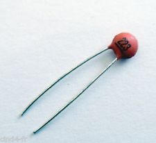
The 223 0.022µF capacitor is a ceramic capacitor with a capacitance of 22 nanofarads (nF) or 0.022 microfarads (µF), equivalent to 22,000 picofarads (pF). Ceramic capacitors are widely used in electronic circuits for their stability, reliability, and low cost.

Key Features:

  • Capacitance: 0.022µF (22nF, 22000pF)
  • Type: Ceramic capacitor
  • Voltage Rating: Commonly ranges from 50V to 100V or higher, depending on the application
  • Temperature Stability: Stable over a wide temperature range
  • Low equivalent series resistance (ESR)

Technical Specifications:

  • Capacitance: 0.022µF (22nF, 22000pF)
  • Voltage Rating: Typically 50V, 100V, or higher (check specific component marking)
  • Tolerance: ±10% or ±20% (varies by manufacturer)
  • Temperature Coefficient: Typically NP0 (C0G) for high stability, or X7R for general-purpose use
  • Operating Temperature Range: -55°C to +125°C (varies by type)
  • Body Size: Depends on the voltage rating and tolerance (e.g., 0805, 1206, etc. for surface mount)
  • Type: Available in through-hole or surface mount packages

Applications:

  • Decoupling and Bypassing: Used to filter out noise in power supply lines.
  • Timing Circuits: Used in conjunction with resistors to create RC timing circuits.
  • Signal Coupling and Decoupling: Facilitates AC signal transmission between circuit stages.
  • Filtering: Used in filter circuits for audio and RF applications.
  • Oscillators: Used in oscillator circuits for frequency determination.

Usage:

  1. Identify the Correct Capacitance Value: Ensure that 0.022µF is the required capacitance for your circuit.
  2. Check the Voltage Rating: Verify that the voltage rating meets or exceeds the circuit requirements.
  3. Position on PCB: Place the capacitor in the appropriate location on the printed circuit board (PCB).
  4. Soldering: Solder the capacitor leads (for through-hole) or pads (for surface mount) to the PCB, ensuring good mechanical and electrical connections.
  5. Verification: Test the circuit to ensure proper functionality and that the capacitor is operating within its specified limits.

Caution:

  • Voltage Rating: Do not exceed the rated voltage to avoid capacitor failure.
  • Polarity: While ceramic capacitors are generally non-polarized, ensure correct orientation if using polarized types.
  • Handling: Handle with care to avoid mechanical damage to the capacitor body and leads.The 223 0.022µF capacitor is a ceramic capacitor with a capacitance of 22 nanofarads (nF) or 0.022 microfarads (µF), equivalent to 22,000 picofarads (pF). Ceramic capacitors are widely used in electronic circuits for their stability, reliability, and low cost.

    Key Features:

    • Capacitance: 0.022µF (22nF, 22000pF)
    • Type: Ceramic capacitor
    • Voltage Rating: Commonly ranges from 50V to 100V or higher, depending on the application
    • Temperature Stability: Stable over a wide temperature range
    • Low equivalent series resistance (ESR)

    Technical Specifications:

    • Capacitance: 0.022µF (22nF, 22000pF)
    • Voltage Rating: Typically 50V, 100V, or higher (check specific component marking)
    • Tolerance: ±10% or ±20% (varies by manufacturer)
    • Temperature Coefficient: Typically NP0 (C0G) for high stability, or X7R for general-purpose use
    • Operating Temperature Range: -55°C to +125°C (varies by type)
    • Body Size: Depends on the voltage rating and tolerance (e.g., 0805, 1206, etc. for surface mount)
    • Type: Available in through-hole or surface mount packages

    Applications:

    • Decoupling and Bypassing: Used to filter out noise in power supply lines.
    • Timing Circuits: Used in conjunction with resistors to create RC timing circuits.
    • Signal Coupling and Decoupling: Facilitates AC signal transmission between circuit stages.
    • Filtering: Used in filter circuits for audio and RF applications.
    • Oscillators: Used in oscillator circuits for frequency determination.

    Usage:

    1. Identify the Correct Capacitance Value: Ensure that 0.022µF is the required capacitance for your circuit.
    2. Check the Voltage Rating: Verify that the voltage rating meets or exceeds the circuit requirements.
    3. Position on PCB: Place the capacitor in the appropriate location on the printed circuit board (PCB).
    4. Soldering: Solder the capacitor leads (for through-hole) or pads (for surface mount) to the PCB, ensuring good mechanical and electrical connections.
    5. Verification: Test the circuit to ensure proper functionality and that the capacitor is operating within its specified limits.

    Caution:

    • Voltage Rating: Do not exceed the rated voltage to avoid capacitor failure.
    • Polarity: While ceramic capacitors are generally non-polarized, ensure correct orientation if using polarized types.
    • Handling: Handle with care to avoid mechanical damage to the capacitor body and leads.

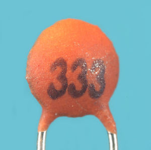
The 333 ceramic capacitor is a small, non-polarized capacitor with a capacitance value of 0.033 microfarads (µF), equivalent to 33 nanofarads (nF) or 33000 picofarads (pF). Ceramic capacitors are commonly used in electronic circuits for various applications including filtering, coupling, and decoupling.

Key Features:

  • Capacitance: 0.033µF (33nF, 33000pF)
  • Type: Ceramic Capacitor
  • Dielectric Material: Often X7R, NPO, or Y5V depending on the specific application requirements
  • Package: Typically comes in various sizes such as 0805, 1206 for surface-mount, or through-hole radial or axial leads

Technical Specifications:

  • Capacitance: 0.033µF (33nF, 33000pF)
  • Voltage Rating: Common ratings include 50V, 100V, 200V, etc.
  • Tolerance: ±10% (K), ±5% (J), or ±20% (M), depending on the type
  • Temperature Coefficient: Varies by dielectric material (e.g., X7R: ±15% over -55°C to +125°C)
  • Operating Temperature Range: -55°C to +125°C
  • Package Type: Available in SMD (surface mount) or through-hole configurations
  • ESR (Equivalent Series Resistance): Low, typical for ceramic capacitors

Applications:

  • Decoupling: Used to filter out noise and stabilize power supply lines in electronic circuits.
  • Coupling: Used to pass AC signals while blocking DC components in signal processing applications.
  • Filtering: Employed in various filter circuits, including audio and RF filters.
  • Timing Circuits: Used in timing applications, such as in RC (resistor-capacitor) timer circuits.
  • Bypass Capacitor: Provides a low-impedance path to ground for high-frequency noise, improving signal integrity.

Usage:

  1. Identify the Correct Value: Ensure that 0.033µF is the required capacitance for your application.
  2. Check Voltage Rating: Verify that the capacitor’s voltage rating is suitable for your circuit.
  3. Position on PCB: Place the capacitor in the appropriate location on the printed circuit board (PCB).
  4. Soldering: For through-hole, solder the leads to the PCB pads. For SMD, place the capacitor on the pads and solder carefully.
  5. Verification: Test the circuit to ensure proper functionality and that the capacitor is operating within its specified limits.

Caution:

  • Voltage Rating: Do not exceed the rated voltage to avoid damaging the capacitor.
  • Handling: Handle with care to avoid damaging the capacitor body or leads, especially for SMD components.
0

TOP

X