Search results for "Resistor

The 473 ceramic capacitor is a non-polarized capacitor with a capacitance value of 0.047 microfarads (µF), equivalent to 47 nanofarads (nF) or 47000 picofarads (pF). Ceramic capacitors are widely used in electronic circuits for applications such as filtering, coupling, and decoupling due to their reliability and low cost.

Key Features:

  • Capacitance: 0.047µF (47nF, 47000pF)
  • Type: Ceramic Capacitor
  • Dielectric Material: Typically X7R, NPO, or Y5V, based on the application needs
  • Package: Available in surface-mount device (SMD) sizes like 0805, 1206, or through-hole radial or axial leads

Technical Specifications:

  • Capacitance: 0.047µF (47nF, 47000pF)
  • Voltage Rating: Common ratings include 50V, 100V, 200V, etc.
  • Tolerance: ±10% (K), ±5% (J), or ±20% (M), depending on the type
  • Temperature Coefficient: Varies by dielectric material (e.g., X7R: ±15% over -55°C to +125°C)
  • Operating Temperature Range: -55°C to +125°C
  • Package Type: Available in SMD (surface mount) or through-hole configurations
  • ESR (Equivalent Series Resistance): Low, typical for ceramic capacitors

Applications:

  • Decoupling: Used to filter out noise and stabilize power supply lines in electronic circuits.
  • Coupling: Passes AC signals while blocking DC components in signal processing applications.
  • Filtering: Employed in various filter circuits, including audio and RF filters.
  • Timing Circuits: Used in timing applications, such as in RC (resistor-capacitor) timer circuits.
  • Bypass Capacitor: Provides a low-impedance path to ground for high-frequency noise, improving signal integrity.

Usage:

  1. Identify the Correct Value: Ensure that 0.047µF is the required capacitance for your application.
  2. Check Voltage Rating: Verify that the capacitor’s voltage rating is suitable for your circuit.
  3. Position on PCB: Place the capacitor in the appropriate location on the printed circuit board (PCB).
  4. Soldering: For through-hole, solder the leads to the PCB pads. For SMD, place the capacitor on the pads and solder carefully.
  5. Verification: Test the circuit to ensure proper functionality and that the capacitor is operating within its specified limits.

Caution:

  • Voltage Rating: Do not exceed the rated voltage to avoid damaging the capacitor.
  • Handling: Handle with care to avoid damaging the capacitor body or leads, especially for SMD components.

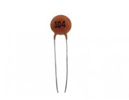
The 104 ceramic capacitor is a non-polarized capacitor with a capacitance value of 0.1 microfarads (µF), equivalent to 100 nanofarads (nF) or 100,000 picofarads (pF). These capacitors are commonly used in various electronic circuits for filtering, coupling, and decoupling applications due to their reliability and cost-effectiveness.

Key Features:

  • Capacitance: 0.1µF (100nF, 100,000pF)
  • Type: Ceramic Capacitor
  • Dielectric Material: Typically X7R, NPO, or Y5V, depending on the application requirements
  • Package: Available in surface-mount device (SMD) sizes such as 0805, 1206, or through-hole radial or axial leads

Technical Specifications:

  • Capacitance: 0.1µF (100nF, 100,000pF)
  • Voltage Rating: Common ratings include 50V, 100V, 200V, etc.
  • Tolerance: ±10% (K), ±5% (J), or ±20% (M), depending on the type
  • Temperature Coefficient: Varies by dielectric material (e.g., X7R: ±15% over -55°C to +125°C)
  • Operating Temperature Range: -55°C to +125°C
  • Package Type: Available in SMD (surface mount) or through-hole configurations
  • ESR (Equivalent Series Resistance): Low, typical for ceramic capacitors

Applications:

  • Decoupling: Used to filter out noise and stabilize power supply lines in electronic circuits.
  • Coupling: Passes AC signals while blocking DC components in signal processing applications.
  • Filtering: Employed in various filter circuits, including audio and RF filters.
  • Timing Circuits: Used in timing applications, such as in RC (resistor-capacitor) timer circuits.
  • Bypass Capacitor: Provides a low-impedance path to ground for high-frequency noise, improving signal integrity.

Usage:

  1. Identify the Correct Value: Ensure that 0.1µF is the required capacitance for your application.
  2. Check Voltage Rating: Verify that the capacitor’s voltage rating is suitable for your circuit.
  3. Position on PCB: Place the capacitor in the appropriate location on the printed circuit board (PCB).
  4. Soldering: For through-hole, solder the leads to the PCB pads. For SMD, place the capacitor on the pads and solder carefully.
  5. Verification: Test the circuit to ensure proper functionality and that the capacitor is operating within its specified limits.

Caution:

  • Voltage Rating: Do not exceed the rated voltage to avoid damaging the capacitor.
  • Handling: Handle with care to avoid damaging the capacitor body or leads, especially for SMD components.


The 0.5 inches 2-digit seven-segment display is an electronic display device used to show numerical information. It consists of two individual seven-segment displays integrated into a single unit, making it ideal for compact digital readouts in various applications. The segments can be independently controlled to display digits from 0 to 9.

Key Features:

  • 0.5-inch digit height
  • Dual-digit display for compact numerical readout
  • Common anode or common cathode configuration (specify as needed)
  • Bright and clear LED segments
  • Low power consumption
  • Easy to interface with microcontrollers and other digital circuits
  • Long-lasting and durable

Technical Specifications:

  • Display Type: Seven-segment
  • Digit Height: 0.5 inches
  • Number of Digits: 2
  • Segment Color: Red (other colors available upon request)
  • Common Configuration: Common anode or common cathode
  • Forward Voltage: Typically 1.8V – 2.2V per segment
  • Forward Current: 10mA – 20mA per segment
  • Power Dissipation: 100mW per segment
  • Operating Temperature Range: -40°C to +85°C
  • Package Type: Through-hole or surface-mount

Applications:

  • Digital Clocks: Displaying time in hours and minutes
  • Counters and Timers: Numerical output for counting events or timing intervals
  • Temperature Displays: Showing temperature readings from sensors
  • Electronic Meters: Readouts for voltmeters, ammeters, and other measuring instruments
  • Consumer Electronics: Numeric display in devices such as microwaves and ovens

Usage:

  1. Determine the common configuration (anode or cathode) and ensure compatibility with your circuit.
  2. Connect the appropriate pins to the microcontroller or driver circuit.
  3. Configure the software to control each segment individually for displaying the desired digits.
  4. Test the display to ensure all segments light up correctly and display the numbers as expected.

Caution:

  • Verify the voltage and current ratings to prevent damage to the display.
  • Handle with care to avoid physical damage to the segments or leads.
  • Ensure proper current limiting resistors are used to protect the LEDs.

Datasheet:
For detailed technical specifications, refer to the 0.5 Inches 2-Digit Seven-Segment Display Datasheet.

The TCS230 is a color sensor used to detect and measure the color of an object. It features an array of photodiodes with red, green, and blue filters, along with a built-in RGB color sensing element. The sensor is widely used in various applications, including color recognition, sorting systems, and educational projects.

Key Features:

  • Integrated RGB color sensing
  • High resolution with 8×8 photodiode array
  • Adjustable light sensitivity
  • Provides digital output (frequency) proportional to the color intensity
  • Simple interfacing with microcontrollers
  • Compact size and low power consumption

Technical Specifications:

  • Photodiode Array: 8×8 pixels (64 total)
  • Output: Digital frequency output (proportional to color intensity)
  • Operating Voltage: 2.7V to 5.5V DC
  • Current Consumption: Approximately 10mA
  • Light Sensitivity: Adjustable via external resistors
  • Temperature Range: -40°C to +85°C
  • Dimensions: 13.8 mm x 13.8 mm
  • Package: 8-pin LCC (Leadless Chip Carrier)

Applications:

  • Color Recognition: Detect and identify colors in various applications
  • Sorting Systems: Sort objects based on color for automation processes
  • Educational Projects: Teach principles of color sensing and electronics
  • Robotics: Use in robots for color-based tasks and navigation
  • Quality Control: Check color consistency in manufacturing processes

Usage:

  1. Connect the TCS230 sensor to a microcontroller or development board according to the pinout configuration.
  2. Configure the sensor’s light sensitivity using external resistors if needed.
  3. Read the frequency output corresponding to the intensity of each color (red, green, blue) using the microcontroller.
  4. Process the color data for your application, such as color detection or sorting.

Caution:

  • Ensure the sensor is connected correctly to avoid damage.
  • Avoid exposing the sensor to direct sunlight or intense light sources to prevent saturation and inaccurate readings.
  • Handle with care to avoid damage to the delicate photodiode array.

Datasheet:
For detailed technical specifications, refer to the TCS230 Datasheet.

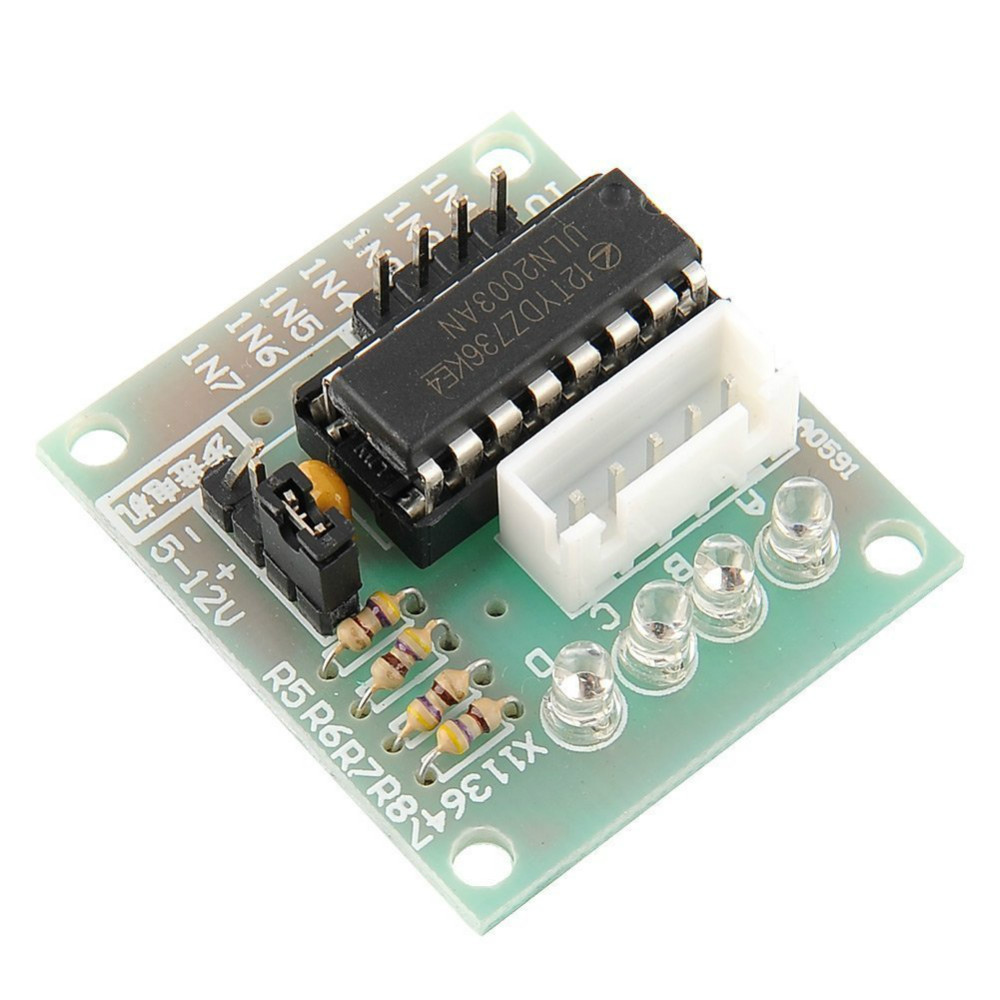
The ULN2003 is a high-voltage, high-current Darlington transistor array designed to drive various loads, including stepper motors, relays, and other high-power devices. It features seven Darlington pairs with common-emitter connections, making it ideal for interfacing between low-power control signals and high-power devices. The ULN2003 is commonly used in applications such as robotics, CNC machines, and industrial automation.

Key Features:

  • 7 NPN Darlington pairs per package
  • Output current (single output) up to 500 mA
  • High-voltage outputs: up to 50V
  • Integrated clamp diodes for inductive load driving
  • Inputs compatible with TTL and 5V CMOS logic
  • Built-in base resistors for easy interface with microcontrollers

Technical Specifications:

  • Package Type: 16-pin DIP, SOIC
  • Output Current: 500 mA per channel
  • Output Voltage: 50V maximum
  • Input Voltage: 5V TTL/CMOS compatible
  • Clamp Diode: Yes (integrated)
  • Pin Configuration: 7 Darlington pairs with common emitters
  • Operating Temperature Range: -20°C to +85°C

Applications:

  • Stepper motor driving
  • Relay driving
  • Lamp and LED displays
  • Logic buffers
  • Line drivers

Usage:

  1. Connect the inputs of the ULN2003 to the control signals from a microcontroller or logic circuit.
  2. Connect the outputs of the ULN2003 to the loads, such as the windings of a stepper motor.
  3. Provide appropriate power supply to the motor or other loads.
  4. Use appropriate software or control logic to drive the inputs, thereby controlling the connected loads.

Caution:

  • Ensure proper heat dissipation if driving high currents through multiple channels.
  • Verify correct power supply voltage and connections before powering the device.
  • Follow the manufacturer’s guidelines for safe operation.

Datasheet: For detailed technical specifications, refer to the ULN2003 Datasheet.

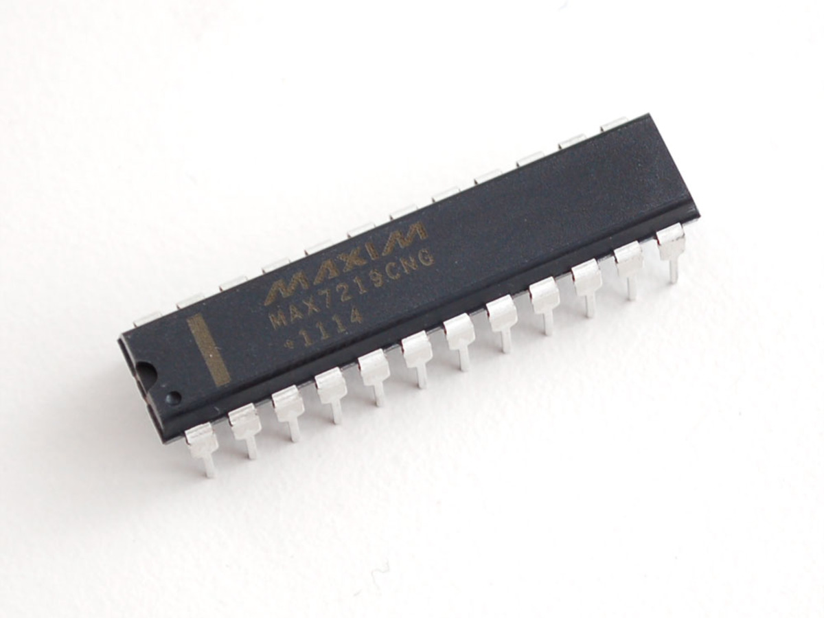
The MAX7219 is a versatile LED display driver IC from Maxim Integrated, designed for controlling 7-segment displays, bar graphs, and other LED configurations. It simplifies the process of driving multiple LEDs by handling the multiplexing and providing control over brightness and data. The MAX7219 is widely used in digital clocks, counters, and various LED display applications.

Key Features:

  • Drives up to 8 digits of 7-segment displays or 64 individual LEDs
  • Integrated BCD (Binary-Coded Decimal) to 7-segment decoding
  • Serial communication via SPI interface
  • Built-in display memory and digit drivers
  • Adjustable brightness with 16 levels of intensity
  • Low power consumption
  • Easy cascading of multiple ICs for larger displays

Technical Specifications:

  • IC Type: LED Display Driver
  • Control Interface: SPI (Serial Peripheral Interface)
  • Output Channels: 8 (for 7-segment displays) or 64 LEDs
  • Brightness Levels: 16
  • Operating Voltage: 4.0V to 5.5V
  • Current Per Segment: Up to 40mA
  • Current Per Digit: Up to 320mA
  • Operating Temperature Range: -40°C to +85°C
  • Package Type: DIP-24, SOIC-24, or TSSOP-24

Applications:

  • Digital clocks and timers
  • LED displays for counters and indicators
  • Home appliances and consumer electronics
  • Industrial equipment displays
  • Prototyping and development projects

Usage:

  1. Connect the MAX7219 to your microcontroller via the SPI interface (DIN, CLK, CS).
  2. Connect the 7-segment displays or LEDs to the output pins of the MAX7219.
  3. Configure the display settings and data via the SPI communication protocol.
  4. Use the MAX7219 to drive and control the displays, adjusting brightness as needed.

Caution:

  • Ensure proper connection of the SPI interface and power supply to avoid malfunction.
  • Verify the current ratings and resistors used with the LEDs to prevent damage.
  • Follow the manufacturer’s guidelines for wiring and programming.

Datasheet:
For detailed technical specifications, refer to the MAX7219 Datasheet.

The 3mm 8×8 Dot Matrix Red LED is a compact and versatile display module consisting of an 8×8 matrix of red LEDs arranged in a grid. It is designed for creating alphanumeric displays, graphical patterns, and various visual indicators in electronic projects. This dot matrix LED is ideal for use in digital clocks, scrolling text displays, and decorative lighting applications.

Key Features:

  • 8×8 matrix arrangement of red LEDs
  • Compact 3mm diameter LED size
  • High brightness with red LED color
  • Suitable for displaying text, graphics, and patterns
  • Commonly used in DIY electronics and display modules

Technical Specifications:

  • LED Type: Red LED Dot Matrix
  • Matrix Size: 8×8 (64 individual LEDs)
  • LED Diameter: 3mm
  • Forward Voltage: Typically 1.8V to 2.2V (for red LEDs)
  • Forward Current: 20mA (per LED, typical)
  • Peak Wavelength: Approximately 620-630nm (red)
  • Viewing Angle: Typically 120° (for red LEDs)
  • Package Type: Dot matrix array

Applications:

  • Alphanumeric displays
  • Scrolling text and graphics
  • Digital clocks and counters
  • Decorative and indicator lighting
  • Educational projects and prototypes

Usage:

  1. Connect the 8×8 dot matrix LED to your control circuit, ensuring proper connection to the row and column pins.
  2. Use appropriate drivers or controllers to manage the LEDs and create the desired display patterns or text.
  3. Power the LEDs with a suitable current-limiting resistor or constant current driver to ensure proper brightness and longevity.

Caution:

  • Ensure proper current-limiting resistors are used to prevent overcurrent and damage to the LEDs.
  • Verify the wiring connections to avoid incorrect display patterns or potential short circuits.
  • Handle the LED matrix carefully to avoid damage to the delicate LED elements.

Datasheet:
For detailed technical specifications, refer to the 3mm 8×8 Dot Matrix Red LED Datasheet.

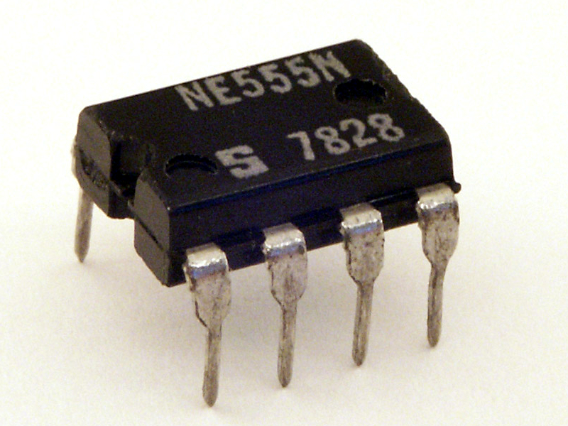
The NE555 timer is a highly stable integrated circuit that can produce accurate time delays or oscillation. It is widely used in timing, pulse generation, and oscillator applications. The NE555 can operate in monostable, astable, and bistable modes, making it a versatile component for various electronic projects and circuits.

Key Features:

  • High precision timing
  • Operates in monostable, astable, and bistable modes
  • Adjustable duty cycle
  • Output is compatible with TTL
  • Can source or sink up to 200mA
  • High-temperature stability
  • Low turn-off time
  • Reliable and cost-effective

Technical Specifications:

  • Operating Voltage: 4.5V to 16V
  • Timing Interval: Microseconds to hours
  • Output Current: 200mA (maximum)
  • Operating Temperature Range: 0°C to +70°C
  • Timing Accuracy: ±1% (typical)
  • Duty Cycle: Adjustable
  • Package Type: DIP-8, SOIC-8
  • Power Dissipation: 600mW (DIP-8), 400mW (SOIC-8)

Applications:

  • Timer circuits
  • Pulse generation
  • Sequential timing
  • Time delay generation
  • Frequency division
  • Square wave oscillators
  • LED and lamp flashers
  • Tone generation
  • Logic clocks

Usage:

  1. Monostable Mode:
    • In this mode, the NE555 operates as a one-shot timer. When triggered by an external pulse, it generates a single output pulse of a specified duration.
    • Connect the external components (resistors and capacitors) to set the desired time delay.
  2. Astable Mode:
    • In this mode, the NE555 operates as an oscillator, generating a continuous square wave output.
    • Connect the external components to set the frequency and duty cycle of the oscillation.
  3. Bistable Mode:
    • In this mode, the NE555 operates as a flip-flop, with two stable states. The output changes state when triggered by external pulses.
    • Configure the external components to use the NE555 as a bistable multivibrator.

Caution:

  • Ensure the power supply voltage is within the specified range to avoid damaging the IC.
  • Verify the correct connection of external components to achieve the desired timing and oscillation characteristics.
  • Handle the IC carefully to avoid electrostatic discharge (ESD) damage.

Datasheet:
For detailed technical specifications, refer to the NE555 Timer Datasheet.

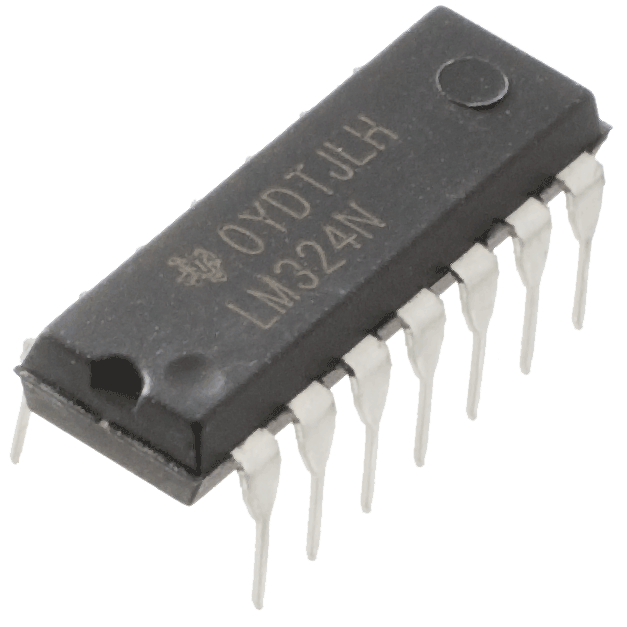
The LM324 is a quad operational amplifier IC that consists of four independent, high-gain, internally frequency-compensated op-amps designed to operate from a single power supply over a wide voltage range. It is suitable for various applications in both analog and digital circuits, including amplifiers, filters, and oscillators. The LM324 is known for its low power consumption and versatility, making it a popular choice in many electronic designs.

Key Features:

  • Four independent op-amps in a single package
  • Single supply operation: 3V to 32V
  • Dual supply operation: ±1.5V to ±16V
  • Low supply current: 700µA per amplifier
  • Internally frequency-compensated for unity gain
  • Wide bandwidth: 1 MHz
  • Low input offset voltage: 2mV
  • Common-mode input voltage range includes ground
  • Output voltage range includes ground

Technical Specifications:

  • Number of Amplifiers: 4
  • Supply Voltage Range: Single supply: 3V to 32V, Dual supply: ±1.5V to ±16V
  • Input Offset Voltage: Typically 2mV
  • Input Bias Current: Typically 20nA
  • Supply Current: 700µA per amplifier
  • Gain Bandwidth Product: 1 MHz
  • Slew Rate: 0.5 V/µs
  • Operating Temperature Range: 0°C to +70°C
  • Package Types: DIP-14, SOIC-14, TSSOP-14

Applications:

  • Signal conditioning
  • Sensor interfacing
  • Active filters
  • Voltage followers
  • Integrators and differentiators
  • Oscillators
  • Comparators
  • Audio pre-amplifiers

Usage:

  1. Single Supply Operation:
    • Connect the Vcc pin to the positive supply voltage and the GND pin to the ground.
    • Configure the input and feedback components according to the desired application (e.g., amplification, filtering).
  2. Dual Supply Operation:
    • Connect the positive supply voltage to the Vcc pin and the negative supply voltage to the Vee pin.
    • Configure the input and feedback components according to the desired application.
  3. Common Applications:
    • Use resistors, capacitors, and other passive components in the feedback loop to set the gain, frequency response, and other parameters of the op-amp circuit.
    • Ensure the input voltage levels are within the specified common-mode range for proper operation.

Caution:

  • Verify the supply voltage and ensure it is within the specified range to avoid damaging the IC.
  • Handle the IC carefully to avoid electrostatic discharge (ESD) damage.
  • Check the pin configuration and connections to prevent incorrect wiring and potential circuit malfunction.

Datasheet:
For detailed technical specifications, refer to the LM324 Datasheet.

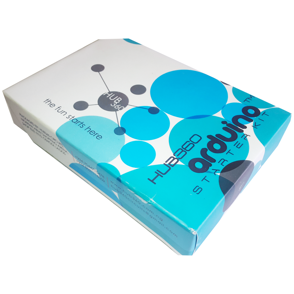
The Hub360 Arduino Starter Kit with SMD Uno is a comprehensive package designed for beginners and enthusiasts looking to dive into the world of electronics and programming. This kit includes an SMD (Surface-Mount Device) version of the Arduino Uno, which is a microcontroller board based on the ATmega328P. The kit provides a variety of components and modules to help users learn and experiment with different electronic projects and concepts.

Key Features:

  • Includes SMD version of the Arduino Uno board
  • Comprehensive set of components and modules for various projects
  • Ideal for beginners and hobbyists
  • Detailed tutorial and project guide included
  • USB interface for easy programming and power
  • Compatible with Arduino IDE and various libraries

Technical Specifications:

  • Microcontroller: ATmega328P
  • Operating Voltage: 5V
  • Input Voltage (recommended): 7-12V
  • Digital I/O Pins: 14 (6 PWM outputs)
  • Analog Input Pins: 6
  • DC Current per I/O Pin: 20mA
  • Flash Memory: 32KB (ATmega328P) of which 0.5KB used by bootloader
  • SRAM: 2KB (ATmega328P)
  • EEPROM: 1KB (ATmega328P)
  • Clock Speed: 16 MHz

Kit Contents:

  • ARDUINO SMD BOARD 1
  • ARDUINO USB CABLE 1
  • ARDUINO BATTERY CONNECTOR 1
  • 400 HOLE BREADBOARD 1
  • LED (RED, YELLOW , GREEN, WHITE) 20
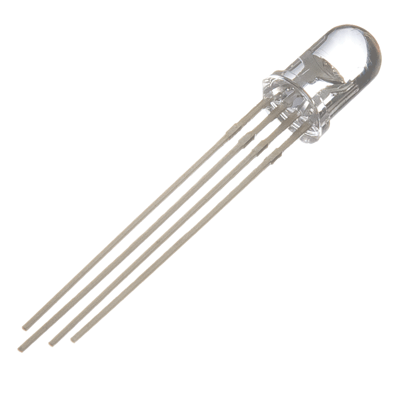
  • RGB LED 1
  • JUMPER WIRE(M-M, M-F, F-F) 120
  • PHOTORESISTOR (LDR) 3
  • MALE HEADERS 40
  • ULTRASONIC SENSOR 1
  • FLAME SENSOR 1
  • TEMP./HUMIDITY SENSOR 1
  • TILT SENSOR 1
  • LASER SENSOR 1
  • PIR MOTION SENSOR 1
  • RESISTORS(220K, 1K, 10K,100K) 40
  • 7 SEGMENT DISPLAY 1
  • SG90 SERVO 1
  •  REMOTE CONTROL 1
  •  BUZZER 1
  •  2N2222 2
  •  TSOP 1838 1
  •  RF TRANSMITTER 1
  •  RF RECEIVER 1
  •  TACT SWITCH 5
  •  16*2 LCD DISPLAY

Applications:

  • Learning basic electronics and programming
  • Building interactive projects and prototypes
  • Developing skills in microcontroller-based design
  • Experimenting with sensors and actuators
  • Creating DIY electronic devices

Usage:

  1. Setup:
    • Connect the SMD Arduino Uno board to your computer using the USB cable.
    • Install the Arduino IDE and configure it to recognize the board.
  2. Programming:
    • Write or upload sample code (sketches) to the Arduino board using the Arduino IDE.
    • Utilize the provided components and modules to build and test different circuits.
  3. Experimentation:
    • Follow the detailed tutorials and project guide to create various projects.
    • Modify and expand on the sample projects to enhance learning and creativity.

Caution:

  • Handle the components carefully to avoid damage.
  • Ensure proper connections and polarity to prevent short circuits or component failure.
  • Verify the code and circuit connections before powering the board.

Datasheet:
For detailed technical specifications of the Arduino Uno, refer to the Arduino Uno Datasheet.

0

TOP

X