Search results for "Resistor

The IRLB8721 is a high-performance N-channel MOSFET (Metal-Oxide-Semiconductor Field-Effect Transistor) designed for efficient switching and amplification applications. It features low on-resistance and high-speed switching capabilities, making it suitable for use in power electronics, motor control, and high-current applications. Its low gate threshold voltage allows for easy interfacing with low-voltage control signals, enhancing its versatility in various electronic designs.

Key Features:

  • Low on-resistance for efficient power switching
  • High-speed switching capability
  • Low gate threshold voltage for easy drive
  • High current handling capacity
  • Suitable for both switching and linear applications
  • Enhanced thermal performance for reliable operation

Technical Specifications:

  • Type: N-channel MOSFET
  • Drain-Source Voltage (Vds): 30V
  • Gate-Source Voltage (Vgs): ±20V
  • Continuous Drain Current (Id): 62A (at Vgs = 10V)
  • Pulsed Drain Current (Id,pulse): 120A
  • On-Resistance (Rds(on)): 0.014Ω (at Vgs = 10V)
  • Gate Threshold Voltage (Vgs(th)): 1.0V to 2.5V
  • Total Gate Charge (Qg): 31nC (typical)
  • Package Type: TO-220

Applications:

  • Power switching in DC-DC converters
  • Motor and relay drivers
  • High-current switching applications
  • Audio amplifiers
  • LED drivers
  • Power management circuits

Usage:

  1. Connect the gate of the IRLB8721 to a suitable control signal through a gate resistor.
  2. Connect the drain to the load and the source to ground.
  3. Ensure that the voltage and current ratings of the MOSFET are not exceeded in your application.
  4. Use proper heatsinking to manage thermal performance and avoid overheating.

Caution:

  • Handle with care to avoid damage from static electricity.
  • Verify that the gate drive voltage is adequate to fully turn on the MOSFET.
  • Ensure proper cooling and heatsinking for high-current applications.

Datasheet:
For detailed technical specifications, refer to the IRLB8721 Datasheet.

The MC34063 is a versatile DC-DC converter integrated circuit designed to provide a stable output voltage from a varying input voltage. It is capable of functioning as a step-up (boost), step-down (buck), or inverting regulator. This flexibility, along with its ease of use and low cost, makes it a popular choice for various power conversion applications in electronics.

Key Features:

  • Capable of step-up (boost), step-down (buck), and inverting voltage regulation
  • Adjustable output voltage with a wide range of input and output voltages
  • High efficiency up to 80% (depending on application and components)
  • Built-in protection features, including thermal shutdown and current limiting
  • Simple design with minimal external components required

Technical Specifications:

  • Input Voltage Range: 3V to 40V
  • Output Voltage Range: Adjustable from 1.25V to 37V
  • Output Current: Up to 1.5A
  • Switching Frequency: 100 kHz (typical)
  • Efficiency: Up to 80% (depends on configuration)
  • Thermal Shutdown: Integrated
  • Current Limiting: Integrated
  • Package Type: Typically available in 8-pin DIP or SOIC packages

Applications:

  • Power supplies for electronic devices
  • Battery-powered applications
  • Voltage level shifting
  • LED drivers
  • Low-power DC-DC converters
  • Inverting and boosting circuits

Usage:

  1. Connect the input voltage to the appropriate pins of the MC34063, following the pin configuration of the package.
  2. Choose external components (inductor, capacitor, and diode) based on the desired output voltage and current, using the datasheet guidelines for calculations.
  3. Adjust the output voltage by configuring the feedback resistors as per the application requirements.
  4. Ensure proper heat dissipation and check for adequate cooling if operating at high currents or power levels.

Caution:

  • Ensure the input and output voltage ratings are within the specified limits to avoid damage.
  • Properly size the external components to meet the design requirements and avoid efficiency losses.
  • Handle the IC with care to avoid damage from electrostatic discharge (ESD).

Datasheet:
For detailed technical specifications, refer to the MC34063 Datasheet.

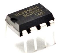
The UC3845 is a high-performance current-mode controller designed for use in switch-mode power supplies (SMPS). It is part of the UC384x family of controllers and is known for its ability to regulate power with high efficiency and stability. The UC3845 offers precise control over the output voltage and current, making it suitable for a variety of power supply applications, including DC-DC converters and AC-DC power supplies.

Key Features:

  • Current-mode control for improved performance and stability
  • Integrated high-current totem pole output stage
  • Adjustable switching frequency for flexibility in design
  • Built-in under-voltage lockout (UVLO) for reliable operation
  • Thermal shutdown and current limiting for protection
  • External compensation for optimizing performance
  • Suitable for both continuous and discontinuous mode operation

Technical Specifications:

  • Input Voltage Range: 8V to 30V (typical)
  • Switching Frequency: Adjustable, typically 100 kHz to 500 kHz
  • Output Current Capability: 1A (peak)
  • Reference Voltage (Vref): 2.5V
  • Current Sense Voltage: Typically 0.5V
  • Thermal Shutdown: Integrated
  • Package Type: Available in 8-pin DIP, SOIC, and other surface-mount packages

Applications:

  • DC-DC converters (buck, boost, buck-boost)
  • AC-DC power supplies
  • Power factor correction circuits
  • Battery chargers
  • Power management systems
  • Inverter circuits

Usage:

  1. Connect the UC3845 to the input power supply and configure the feedback network to set the desired output voltage.
  2. Use external components (inductor, capacitor, and sense resistor) to establish the switching frequency, compensation, and current sensing.
  3. Adjust the external compensation network to ensure stability and optimal performance.
  4. Ensure proper heat dissipation and cooling if operating at high power levels.

Caution:

  • Verify the input voltage and output current ratings to avoid exceeding the device’s specifications.
  • Properly design the external components to match the required performance criteria.
  • Handle with care to avoid damage from electrostatic discharge (ESD) and follow recommended operating conditions.

Datasheet:
For detailed technical specifications, refer to the UC3845 Datasheet.

The LM2596-ADJ is a versatile and highly efficient DC-DC buck (step-down) voltage regulator designed to convert a higher input voltage to a lower, regulated output voltage. It is part of the LM2596 series from Texas Instruments and is known for its ease of use, reliability, and robust performance. The adjustable version (ADJ) allows for a wide range of output voltages, making it suitable for various applications requiring precise voltage regulation.

Key Features:

  • Adjustable output voltage for flexibility in various applications
  • High efficiency up to 75% (depends on configuration and load)
  • Can supply up to 3A of continuous output current
  • Built-in thermal overload protection and short-circuit protection
  • Low ripple and noise for stable output
  • Simple external component design for ease of use

Technical Specifications:

  • Input Voltage Range: 4V to 40V
  • Output Voltage Range: Adjustable from 1.23V to 37V
  • Output Current: Up to 3A
  • Efficiency: Up to 75% (depends on load and configuration)
  • Switching Frequency: 150 kHz (typical)
  • Ripple and Noise: Typically <30mV
  • Thermal Shutdown: Integrated
  • Package Type: Typically available in TO-220, TO-263, and other surface-mount packages

Applications:

  • Power supplies for electronic devices
  • Battery-powered applications
  • LED drivers
  • Adjustable voltage regulators
  • Power management in electronic circuits
  • DIY electronics projects

Usage:

  1. Connect the input voltage to the appropriate pins of the LM2596-ADJ.
  2. Use external resistors to set the desired output voltage according to the feedback network.
  3. Connect the output to the load and ensure that the current requirements do not exceed the regulator’s capacity.
  4. Implement appropriate heat sinking if operating at high currents to ensure thermal stability.

Caution:

  • Verify that the input and output voltage ratings are within the specified limits to avoid damage.
  • Properly size and place external components (e.g., capacitors, inductors) to achieve desired performance and stability.
  • Handle the regulator with care to avoid damage from electrostatic discharge (ESD) and follow recommended operating conditions.

Datasheet:
For detailed technical specifications, refer to the LM2596-ADJ Datasheet.

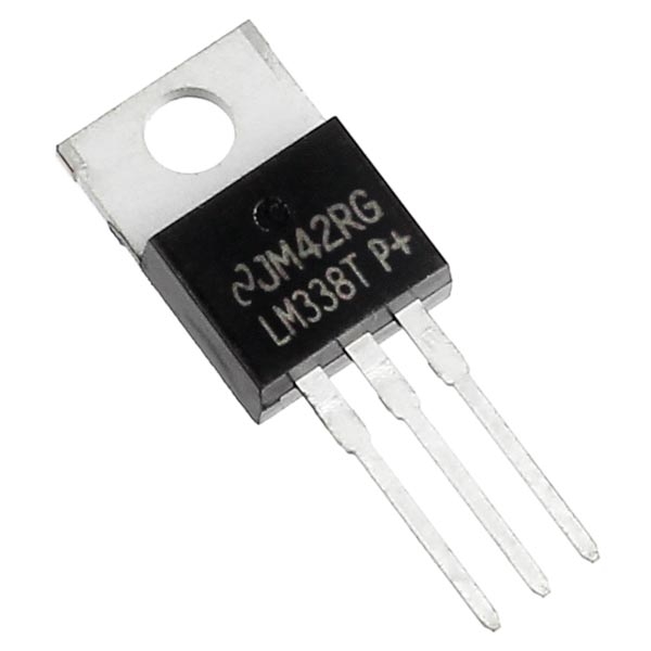
The LM338 is a high-current adjustable voltage regulator designed to provide a stable and regulated output voltage with high current capabilities. It can supply up to 5A of output current and is commonly used in power supplies and voltage regulation applications where adjustable output voltage is required. The LM338 offers flexibility in design and ease of use, making it suitable for a wide range of applications.

Key Features:

  • Adjustable output voltage for customizable applications
  • High current capability up to 5A
  • Low dropout voltage for improved performance in low-voltage applications
  • Built-in thermal overload protection and short-circuit protection
  • Simple design with minimal external components
  • Compatible with a wide range of input and output voltages

Technical Specifications:

  • Input Voltage Range: Up to 40V
  • Output Voltage Range: Adjustable from 1.2V to 37V
  • Output Current: Up to 5A
  • Dropout Voltage: Typically 2V (depends on output current and temperature)
  • Line Regulation: Typically 0.01%/V
  • Load Regulation: Typically 0.1% (at 5A load)
  • Thermal Overload Protection: Integrated
  • Short-Circuit Protection: Integrated
  • Package Type: Available in TO-220, TO-3, and other packages

Applications:

  • Power supplies for electronic devices
  • Adjustable voltage regulators
  • Battery chargers
  • Voltage regulation in DC-DC converters
  • Laboratory power supplies
  • Testing and prototyping

Usage:

  1. Connect the input voltage to the appropriate pins of the LM338, ensuring the input voltage is within the specified range.
  2. Use external resistors to set the desired output voltage according to the formula provided in the datasheet.
  3. Connect the load to the output and ensure that the current requirements do not exceed the regulator’s maximum capacity.
  4. Implement appropriate heat sinking if operating at high currents to ensure thermal stability and prevent overheating.

Caution:

  • Verify the input and output voltage ratings are within the specified limits to avoid damage.
  • Properly size and place external components (e.g., capacitors, resistors) to achieve desired performance and stability.
  • Ensure adequate cooling and heat dissipation to prevent thermal shutdown and ensure reliable operation.

Datasheet:
For detailed technical specifications, refer to the LM338 Datasheet.

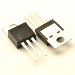
The LM350 is a robust and versatile adjustable voltage regulator capable of providing a stable output with up to 3A of current. It is designed to offer adjustable output voltages for flexible power supply solutions. The LM350 is well-suited for a variety of applications requiring precise voltage regulation and high current output, including power supplies for electronic devices, battery chargers, and other power management systems.

Key Features:

  • Adjustable output voltage for flexibility in various applications
  • High current capability up to 3A
  • Low dropout voltage for efficient performance
  • Built-in thermal overload protection and short-circuit protection
  • Simple external component design for ease of use
  • Compatible with a wide range of input and output voltages

Technical Specifications:

  • Input Voltage Range: Up to 40V
  • Output Voltage Range: Adjustable from 1.25V to 37V
  • Output Current: Up to 3A
  • Dropout Voltage: Typically 2.5V (depends on output current and temperature)
  • Line Regulation: Typically 0.01%/V
  • Load Regulation: Typically 0.1% (at 3A load)
  • Thermal Overload Protection: Integrated
  • Short-Circuit Protection: Integrated
  • Package Type: Available in TO-220 and other packages

Applications:

  • Power supplies for electronic devices
  • Adjustable voltage regulators
  • Battery chargers
  • Voltage regulation in DC-DC converters
  • Laboratory power supplies
  • Testing and prototyping

Usage:

  1. Connect the input voltage to the appropriate pins of the LM350, ensuring the input voltage is within the specified range.
  2. Use external resistors to set the desired output voltage according to the formula provided in the datasheet.
  3. Connect the load to the output and ensure that the current requirements do not exceed the regulator’s maximum capacity.
  4. Implement appropriate heat sinking if operating at high currents to ensure thermal stability and prevent overheating.

Caution:

  • Verify that the input and output voltage ratings are within the specified limits to avoid damage.
  • Properly size and place external components (e.g., capacitors, resistors) to achieve desired performance and stability.
  • Ensure adequate cooling and heat dissipation to prevent thermal shutdown and ensure reliable operation.

Datasheet:
For detailed technical specifications, refer to the LM350 Datasheet.

The KA3525 is a versatile pulse-width modulation (PWM) controller designed for high-efficiency DC-DC converters, inverters, and other power management applications. It integrates multiple functions into a single chip, including a voltage reference, error amplifier, and PWM control circuitry. The KA3525 is known for its flexibility, high performance, and ease of use in designing various switching power supplies.

Key Features:

  • Integrated PWM control for efficient power conversion
  • Adjustable output voltage for customizable applications
  • Built-in voltage reference for stable operation
  • Error amplifier for precise regulation
  • Adjustable dead-time control for improved performance
  • High-speed switching capability for efficient operation
  • Multiple protection features including overcurrent and thermal protection

Technical Specifications:

  • Input Voltage Range: 7V to 40V
  • Output Voltage Range: Adjustable, depending on external components
  • Switching Frequency: Adjustable, typically up to 100 kHz
  • Voltage Reference: 2.5V ±1% (typical)
  • Error Amplifier Gain: 10 to 1000
  • Dead-Time Control: Adjustable
  • Thermal Shutdown: Integrated
  • Overcurrent Protection: Integrated
  • Package Type: Typically available in DIP-16 and surface-mount packages

Applications:

  • DC-DC converters (buck, boost, and flyback)
  • Power inverters for renewable energy systems
  • Switching power supplies for electronic devices
  • Battery chargers
  • Motor control circuits
  • High-efficiency power management systems

Usage:

  1. Connect the input voltage to the appropriate pins of the KA3525, ensuring it is within the specified range.
  2. Configure the output voltage using external resistors and feedback network as specified in the datasheet.
  3. Set the switching frequency and dead-time control according to your application requirements.
  4. Connect the load to the output and ensure proper cooling and heat dissipation.

Caution:

  • Ensure that the input voltage is within the specified limits to avoid damage to the chip.
  • Properly design the external components (e.g., inductors, capacitors) to achieve desired performance and stability.
  • Implement thermal management and protection features to prevent overheating and ensure reliable operation.

Datasheet:
For detailed technical specifications, refer to the KA3525 Datasheet.

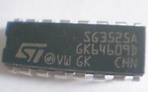
The SG3525 is a versatile pulse-width modulation (PWM) controller used for designing high-efficiency switching power supplies, including DC-DC converters and inverters. It integrates several key functions such as a voltage reference, error amplifier, and PWM control circuitry, offering a comprehensive solution for power management applications. The SG3525 is well-regarded for its performance, reliability, and ease of integration into various power supply designs.

Key Features:

  • Integrated PWM control for efficient power conversion
  • Adjustable output voltage for flexibility in design
  • Built-in voltage reference for stable operation
  • Error amplifier for precise voltage regulation
  • Adjustable dead-time and frequency control for optimal performance
  • High-speed switching capability with improved efficiency
  • Built-in protection features including thermal shutdown and overcurrent protection

Technical Specifications:

  • Input Voltage Range: 7V to 40V
  • Output Voltage Range: Adjustable, based on external components
  • Switching Frequency: Adjustable, typically up to 100 kHz
  • Voltage Reference: 2.5V ±1% (typical)
  • Error Amplifier Gain: Adjustable
  • Dead-Time Control: Adjustable
  • Thermal Shutdown: Integrated
  • Overcurrent Protection: Integrated
  • Package Type: Available in DIP-16 and surface-mount packages

Applications:

  • DC-DC converters (buck, boost, and flyback topologies)
  • Power inverters for renewable energy systems
  • Switching power supplies for various electronic devices
  • Battery chargers
  • Motor control circuits
  • High-efficiency power management systems

Usage:

  1. Connect the input voltage to the appropriate pins of the SG3525, ensuring it is within the specified range.
  2. Set the desired output voltage using external resistors and the feedback network, as outlined in the datasheet.
  3. Adjust the switching frequency and dead-time according to the requirements of your application.
  4. Connect the load to the output and ensure adequate cooling and heat dissipation for reliable operation.

Caution:

  • Verify that the input voltage is within the specified limits to avoid damage to the chip.
  • Properly select and place external components (e.g., inductors, capacitors) to achieve optimal performance and stability.
  • Implement thermal management and protection mechanisms to prevent overheating and ensure the reliability of the power supply.

Datasheet:
For detailed technical specifications, refer to the SG3525 Datasheet.

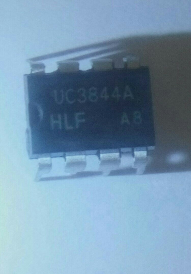
The UC3844 is a high-performance pulse-width modulation (PWM) controller designed for use in switching power supplies and other power conversion applications. It provides integrated control and protection features for efficient and stable power regulation. The UC3844 is known for its high-speed operation, low standby current, and ease of use in various power management designs.

Key Features:

  • Integrated PWM control for efficient power regulation
  • Adjustable output voltage for flexible design
  • Built-in voltage reference for stable operation
  • Error amplifier for precise regulation
  • High-speed switching capability with minimal external components
  • Built-in protection features including overcurrent, thermal shutdown, and undervoltage lockout

Technical Specifications:

  • Input Voltage Range: 7V to 40V
  • Output Voltage Range: Adjustable, based on external components
  • Switching Frequency: Typically 100 kHz
  • Voltage Reference: 2.5V ±1% (typical)
  • Error Amplifier Gain: Adjustable
  • Dead-Time Control: Not directly adjustable; typically handled by external components
  • Thermal Shutdown: Integrated
  • Overcurrent Protection: Integrated
  • Undervoltage Lockout: Integrated
  • Package Type: Available in DIP-8 and surface-mount packages

Applications:

  • DC-DC converters (buck, boost, and flyback topologies)
  • Switching power supplies for various electronic devices
  • Battery chargers
  • Power management for industrial and consumer electronics
  • High-efficiency power converters and inverters

Usage:

  1. Connect the input voltage to the appropriate pins of the UC3844, ensuring it is within the specified range.
  2. Configure the output voltage using external resistors and the feedback network, as outlined in the datasheet.
  3. Set the switching frequency and other parameters according to your application requirements using external components.
  4. Connect the load to the output and ensure proper thermal management and heat dissipation.

Caution:

  • Ensure that the input voltage is within the specified limits to prevent damage to the controller.
  • Properly design and place external components (e.g., inductors, capacitors) to achieve desired performance and stability.
  • Implement adequate cooling and protection mechanisms to maintain reliable operation and prevent overheating.

Datasheet:
For detailed technical specifications, refer to the UC3844 Datasheet.

The SG6841 is a high-performance pulse-width modulation (PWM) controller designed for use in various switching power supply applications. It is known for its reliable performance in voltage regulation and power management. The SG6841 integrates several key functions, including PWM control, error amplification, and protection features, making it suitable for designing efficient and stable power supplies.

Key Features:

  • Integrated PWM control for efficient power regulation
  • Adjustable output voltage for flexible design
  • Built-in voltage reference for stable operation
  • Error amplifier for precise voltage regulation
  • Adjustable switching frequency for optimization
  • Built-in protection features including thermal shutdown and overcurrent protection
  • Low standby current for improved efficiency

Technical Specifications:

  • Input Voltage Range: 8V to 40V
  • Output Voltage Range: Adjustable, based on external components
  • Switching Frequency: Adjustable, typically up to 100 kHz
  • Voltage Reference: 2.5V ±1% (typical)
  • Error Amplifier Gain: Adjustable
  • Thermal Shutdown: Integrated
  • Overcurrent Protection: Integrated
  • Package Type: Typically available in DIP-8 and surface-mount packages

Applications:

  • DC-DC converters (buck, boost, and flyback topologies)
  • Power supplies for various electronic devices
  • Battery chargers
  • Power management in industrial and consumer electronics
  • High-efficiency power converters and inverters

Usage:

  1. Connect the input voltage to the appropriate pins of the SG6841, ensuring it is within the specified range.
  2. Configure the output voltage using external resistors and feedback network as described in the datasheet.
  3. Adjust the switching frequency and other parameters according to your application requirements.
  4. Connect the load to the output and ensure proper thermal management and heat dissipation.

Caution:

  • Ensure that the input voltage is within the specified limits to avoid damage to the chip.
  • Properly design and place external components (e.g., inductors, capacitors) to achieve optimal performance and stability.
  • Implement adequate cooling and protection mechanisms to maintain reliable operation and prevent overheating.

Datasheet:
For detailed technical specifications, refer to the SG6841 Datasheet.

0

TOP

X