Search results for "Resistor

The IRF630 is an N-channel power MOSFET designed for high-voltage and moderate-current applications. It provides efficient switching and is ideal for use in power supplies, motor control circuits, and various high-power electronic applications.

Key Features:

  • N-channel enhancement mode MOSFET
  • High voltage rating: 200V
  • Moderate current rating: 9.3A
  • Low on-resistance for efficient switching
  • Fast switching capabilities
  • Rugged and reliable construction
  • Suitable for high-frequency applications

Technical Specifications:

  • Type: N-channel MOSFET
  • Drain-Source Voltage (Vds): 200V
  • Continuous Drain Current (Id): 9.3A
  • Pulsed Drain Current (Id, Pulse): 37A
  • Gate-Source Voltage (Vgs): ±20V
  • Rds(on): 0.4Ω (maximum) at Vgs = 10V
  • Total Gate Charge (Qg): 38nC (typical)
  • Gate-Source Threshold Voltage (Vgs(th)): 2.0V – 4.0V
  • Power Dissipation (Pd): 74W
  • Operating Temperature Range: -55°C to +150°C
  • Package Type: TO-220

Applications:

  • Switched-mode power supplies (SMPS)
  • Motor control circuits
  • DC-DC converters
  • Inverters and amplifiers
  • Load switches
  • Automotive electronics
  • Power management systems

Usage:

  1. Connect the drain terminal to the load or power supply.
  2. Connect the source terminal to the ground or low-side of the circuit.
  3. Apply a suitable gate voltage (Vgs) to control the switching operation.
  4. Use a gate resistor if needed to manage switching speed and reduce noise.
  5. Ensure proper heat sinking to handle power dissipation and prevent overheating.

Caution:

  • Handle the MOSFET carefully to avoid damage from electrostatic discharge (ESD).
  • Verify the voltage and current ratings to ensure compatibility with your circuit.
  • Ensure adequate cooling and heat dissipation to prevent thermal overload.

Datasheet:
For detailed technical specifications, refer to the IRF630 Datasheet.

The IRF9640 is a P-channel power MOSFET designed for high-voltage and moderate-current applications. It provides efficient switching and is suitable for use in power supplies, motor control circuits, and various high-power electronic applications.

Key Features:

  • P-channel enhancement mode MOSFET
  • High voltage rating: 200V
  • Moderate current rating: 11A
  • Low on-resistance for efficient switching
  • Fast switching capabilities
  • Rugged and reliable construction
  • Suitable for high-frequency applications

Technical Specifications:

  • Type: P-channel MOSFET
  • Drain-Source Voltage (Vds): -200V
  • Continuous Drain Current (Id): -11A
  • Pulsed Drain Current (Id, Pulse): -44A
  • Gate-Source Voltage (Vgs): ±20V
  • Rds(on): 0.500Ω (maximum) at Vgs = -10V
  • Total Gate Charge (Qg): 72nC (typical)
  • Gate-Source Threshold Voltage (Vgs(th)): -2.0V to -4.0V
  • Power Dissipation (Pd): 83W
  • Operating Temperature Range: -55°C to +150°C
  • Package Type: TO-220

Applications:

  • Switched-mode power supplies (SMPS)
  • Motor control circuits
  • DC-DC converters
  • Inverters and amplifiers
  • Load switches
  • Automotive electronics
  • Power management systems

Usage:

  1. Connect the drain terminal to the high-side load or power supply.
  2. Connect the source terminal to the low-side or ground of the circuit.
  3. Apply a suitable gate voltage (Vgs) to control the switching operation.
  4. Use a gate resistor if needed to control the switching speed and reduce noise.
  5. Ensure proper heat sinking to handle power dissipation and prevent overheating.

Caution:

  • Handle the MOSFET carefully to avoid damage from electrostatic discharge (ESD).
  • Verify the voltage and current ratings to ensure compatibility with your circuit.
  • Ensure adequate cooling and heat dissipation to prevent thermal overload.

Datasheet:
For detailed technical specifications, refer to the IRF9640 Datasheet.

The IRF1404 is an N-channel power MOSFET designed for high-current, low-voltage applications. It offers extremely low on-resistance and efficient switching, making it ideal for use in power supplies, motor control circuits, and other high-power electronic applications.

Key Features:

  • N-channel enhancement mode MOSFET
  • High current rating: 162A
  • Low on-resistance for efficient switching
  • Voltage rating: 40V
  • Fast switching capabilities
  • Rugged and reliable construction
  • Suitable for high-frequency applications

Technical Specifications:

  • Type: N-channel MOSFET
  • Drain-Source Voltage (Vds): 40V
  • Continuous Drain Current (Id): 162A
  • Pulsed Drain Current (Id, Pulse): 600A
  • Gate-Source Voltage (Vgs): ±20V
  • Rds(on): 0.0025Ω (maximum) at Vgs = 10V
  • Total Gate Charge (Qg): 170nC (typical)
  • Gate-Source Threshold Voltage (Vgs(th)): 2.0V – 4.0V
  • Power Dissipation (Pd): 200W
  • Operating Temperature Range: -55°C to +175°C
  • Package Type: TO-220

Applications:

  • Power supplies (SMPS)
  • Motor control circuits
  • DC-DC converters
  • Inverters and amplifiers
  • Load switches
  • Automotive electronics
  • Power management systems

Usage:

  1. Connect the drain terminal to the load or power supply.
  2. Connect the source terminal to the ground or low-side of the circuit.
  3. Apply a suitable gate voltage (Vgs) to control the switching operation.
  4. Use a gate resistor if needed to manage switching speed and reduce noise.
  5. Ensure proper heat sinking to handle power dissipation and prevent overheating.

Caution:

  • Handle the MOSFET carefully to avoid damage from electrostatic discharge (ESD).
  • Verify the voltage and current ratings to ensure compatibility with your circuit.
  • Ensure adequate cooling and heat dissipation to prevent thermal overload.

Datasheet:
For detailed technical specifications, refer to the IRF1404 Datasheet.

The IRF830 is an N-channel power MOSFET designed for high-voltage applications. With its high voltage rating and moderate current capability, it is suitable for use in power supplies, motor control circuits, and various other high-power electronic applications.

Key Features:

  • N-channel enhancement mode MOSFET
  • High voltage rating: 500V
  • Moderate current rating: 4.5A
  • Low on-resistance for efficient switching
  • Fast switching capabilities
  • Rugged and reliable construction
  • Suitable for high-frequency applications

Technical Specifications:

  • Type: N-channel MOSFET
  • Drain-Source Voltage (Vds): 500V
  • Continuous Drain Current (Id): 4.5A
  • Pulsed Drain Current (Id, Pulse): 18A
  • Gate-Source Voltage (Vgs): ±20V
  • Rds(on): 1.5Ω (maximum) at Vgs = 10V
  • Total Gate Charge (Qg): 42nC (typical)
  • Gate-Source Threshold Voltage (Vgs(th)): 2.0V – 4.0V
  • Power Dissipation (Pd): 74W
  • Operating Temperature Range: -55°C to +150°C
  • Package Type: TO-220

Applications:

  • Switched-mode power supplies (SMPS)
  • Motor control circuits
  • DC-DC converters
  • Inverters and amplifiers
  • Load switches
  • Automotive electronics
  • Power management systems

Usage:

  1. Connect the drain terminal to the load or power supply.
  2. Connect the source terminal to the ground or low-side of the circuit.
  3. Apply a suitable gate voltage (Vgs) to control the switching operation.
  4. Use a gate resistor if needed to control the switching speed and reduce noise.
  5. Ensure proper heat sinking to handle power dissipation and prevent overheating.

Caution:

  • Handle the MOSFET carefully to avoid damage from electrostatic discharge (ESD).
  • Verify the voltage and current ratings to ensure compatibility with your circuit.
  • Ensure adequate cooling and heat dissipation to prevent thermal overload.

Datasheet:
For detailed technical specifications, refer to the IRF830 Datasheet.

The IRF530 is an N-channel power MOSFET designed for high-voltage and high-current applications. It provides efficient switching with its low on-resistance, making it suitable for use in power supplies, motor control circuits, and various high-power electronic systems.

Key Features:

  • N-channel enhancement mode MOSFET
  • High voltage rating: 100V
  • High current rating: 17A
  • Low on-resistance for efficient switching
  • Fast switching capabilities
  • Rugged and reliable construction
  • Suitable for high-frequency applications

Technical Specifications:

  • Type: N-channel MOSFET
  • Drain-Source Voltage (Vds): 100V
  • Continuous Drain Current (Id): 17A
  • Pulsed Drain Current (Id, Pulse): 68A
  • Gate-Source Voltage (Vgs): ±20V
  • Rds(on): 0.160Ω (maximum) at Vgs = 10V
  • Total Gate Charge (Qg): 67nC (typical)
  • Gate-Source Threshold Voltage (Vgs(th)): 2.0V – 4.0V
  • Power Dissipation (Pd): 110W
  • Operating Temperature Range: -55°C to +175°C
  • Package Type: TO-220

Applications:

  • Switched-mode power supplies (SMPS)
  • Motor control circuits
  • DC-DC converters
  • Inverters and amplifiers
  • Load switches
  • Automotive electronics
  • Power management systems

Usage:

  1. Connect the drain terminal to the load or power supply.
  2. Connect the source terminal to the ground or low-side of the circuit.
  3. Apply a suitable gate voltage (Vgs) to control the switching operation.
  4. Use a gate resistor if needed to control the switching speed and reduce noise.
  5. Ensure proper heat sinking to handle power dissipation and prevent overheating.

Caution:

  • Handle the MOSFET carefully to avoid damage from electrostatic discharge (ESD).
  • Verify the voltage and current ratings to ensure compatibility with your circuit.
  • Ensure adequate cooling and heat dissipation to prevent thermal overload.

Datasheet:
For detailed technical specifications, refer to the IRF530 Datasheet.

The IRF640 is an N-channel power MOSFET designed for high-voltage and high-current applications. It offers efficient switching and low on-resistance, making it ideal for use in power supplies, motor control circuits, and various high-power electronic applications.

Key Features:

  • N-channel enhancement mode MOSFET
  • High voltage rating: 200V
  • High current rating: 18A
  • Low on-resistance for efficient switching
  • Fast switching capabilities
  • Rugged and reliable construction
  • Suitable for high-frequency applications

Technical Specifications:

  • Type: N-channel MOSFET
  • Drain-Source Voltage (Vds): 200V
  • Continuous Drain Current (Id): 18A
  • Pulsed Drain Current (Id, Pulse): 72A
  • Gate-Source Voltage (Vgs): ±20V
  • Rds(on): 0.180Ω (maximum) at Vgs = 10V
  • Total Gate Charge (Qg): 67nC (typical)
  • Gate-Source Threshold Voltage (Vgs(th)): 2.0V – 4.0V
  • Power Dissipation (Pd): 125W
  • Operating Temperature Range: -55°C to +175°C
  • Package Type: TO-220

Applications:

  • Switched-mode power supplies (SMPS)
  • Motor control circuits
  • DC-DC converters
  • Inverters and amplifiers
  • Load switches
  • Automotive electronics
  • Power management systems

Usage:

  1. Connect the drain terminal to the load or power supply.
  2. Connect the source terminal to the ground or low-side of the circuit.
  3. Apply a suitable gate voltage (Vgs) to control the switching operation.
  4. Use a gate resistor if needed to manage switching speed and reduce noise.
  5. Ensure proper heat sinking to handle power dissipation and prevent overheating.

Caution:

  • Handle the MOSFET carefully to avoid damage from electrostatic discharge (ESD).
  • Verify the voltage and current ratings to ensure compatibility with your circuit.
  • Ensure adequate cooling and heat dissipation to prevent thermal overload.

Datasheet:
For detailed technical specifications, refer to the IRF640 Datasheet.

The IRF2807 is an N-channel power MOSFET designed for high-current, low-voltage applications. It offers low on-resistance and efficient switching, making it suitable for use in power supplies, motor control circuits, and other high-power electronic systems.

Key Features:

  • N-channel enhancement mode MOSFET
  • High current rating: 82A
  • Low on-resistance for efficient switching
  • Voltage rating: 75V
  • Fast switching capabilities
  • Rugged and reliable construction
  • Suitable for high-frequency applications

Technical Specifications:

  • Type: N-channel MOSFET
  • Drain-Source Voltage (Vds): 75V
  • Continuous Drain Current (Id): 82A
  • Pulsed Drain Current (Id, Pulse): 300A
  • Gate-Source Voltage (Vgs): ±20V
  • Rds(on): 0.006Ω (maximum) at Vgs = 10V
  • Total Gate Charge (Qg): 165nC (typical)
  • Gate-Source Threshold Voltage (Vgs(th)): 2.0V – 4.0V
  • Power Dissipation (Pd): 100W
  • Operating Temperature Range: -55°C to +175°C
  • Package Type: TO-220

Applications:

  • Power supplies (SMPS)
  • Motor control circuits
  • DC-DC converters
  • Inverters and amplifiers
  • Load switches
  • Automotive electronics
  • Power management systems

Usage:

  1. Connect the drain terminal to the load or power supply.
  2. Connect the source terminal to the ground or low-side of the circuit.
  3. Apply a suitable gate voltage (Vgs) to control the switching operation.
  4. Use a gate resistor if needed to manage switching speed and reduce noise.
  5. Ensure proper heat sinking to handle power dissipation and prevent overheating.

Caution:

  • Handle the MOSFET carefully to avoid damage from electrostatic discharge (ESD).
  • Verify the voltage and current ratings to ensure compatibility with your circuit.
  • Ensure adequate cooling and heat dissipation to prevent thermal overload.

Datasheet:
For detailed technical specifications, refer to the IRF2807 Datasheet.

The IRF840 is an N-channel power MOSFET designed for high-voltage applications. It provides efficient switching with a high voltage rating and moderate current capability, making it suitable for use in power supplies, motor control circuits, and other high-power electronic systems.

Key Features:

  • N-channel enhancement mode MOSFET
  • High voltage rating: 500V
  • Moderate current rating: 8A
  • Low on-resistance for efficient switching
  • Fast switching capabilities
  • Rugged and reliable construction
  • Suitable for high-frequency applications

Technical Specifications:

  • Type: N-channel MOSFET
  • Drain-Source Voltage (Vds): 500V
  • Continuous Drain Current (Id): 8A
  • Pulsed Drain Current (Id, Pulse): 30A
  • Gate-Source Voltage (Vgs): ±20V
  • Rds(on): 0.850Ω (maximum) at Vgs = 10V
  • Total Gate Charge (Qg): 105nC (typical)
  • Gate-Source Threshold Voltage (Vgs(th)): 2.0V – 4.0V
  • Power Dissipation (Pd): 94W
  • Operating Temperature Range: -55°C to +150°C
  • Package Type: TO-220

Applications:

  • Switched-mode power supplies (SMPS)
  • Motor control circuits
  • DC-DC converters
  • Inverters and amplifiers
  • Load switches
  • Automotive electronics
  • Power management systems

Usage:

  1. Connect the drain terminal to the load or power supply.
  2. Connect the source terminal to the ground or low-side of the circuit.
  3. Apply a suitable gate voltage (Vgs) to control the switching operation.
  4. Use a gate resistor if needed to manage switching speed and reduce noise.
  5. Ensure proper heat sinking to handle power dissipation and prevent overheating.

Caution:

  • Handle the MOSFET carefully to avoid damage from electrostatic discharge (ESD).
  • Verify the voltage and current ratings to ensure compatibility with your circuit.
  • Ensure adequate cooling and heat dissipation to prevent thermal overload.

Datasheet:
For detailed technical specifications, refer to the IRF840 Datasheet.

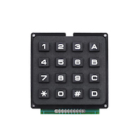
The Plastic Keyboard 4×4 is a compact, matrix-style keypad featuring 16 individual keys arranged in a 4×4 grid. This keypad is designed for use in various electronic projects and applications, including access control systems, password input, and menu navigation. Its durable plastic construction ensures long-lasting performance, while its simple interface makes it easy to integrate with microcontrollers and other digital circuits.

Key Features:

  • 16 keys arranged in a 4×4 matrix layout
  • Durable plastic construction
  • Simple interface for easy integration with microcontrollers
  • Low-profile design
  • Key legends: numbers 0-9, A-D, *, #
  • Compatible with various programming platforms (Arduino, Raspberry Pi, etc.)

Technical Specifications:

  • Number of Keys: 16
  • Matrix Size: 4×4
  • Material: Plastic
  • Key Legends: 0-9, A-D, *, #
  • Dimensions: Approximately 70mm x 77mm x 10mm
  • Weight: Approximately 20 grams
  • Connector Type: 8-pin (4 rows, 4 columns)
  • Operating Voltage: 3.3V to 5V (depends on the connected microcontroller)
  • Current Rating: Typically less than 20mA

Applications:

  • Access control systems (e.g., PIN entry for security systems)
  • User interface for embedded systems
  • Menu navigation for various electronic devices
  • DIY electronics projects
  • Robotics control panels

Usage:

  1. Connect the keypad to a microcontroller or other digital input device using the 8-pin connector.
  2. Configure the microcontroller’s software to read the matrix layout of the keypad.
  3. Assign functions or commands to each key as required for your application.
  4. Integrate the keypad into your project enclosure, ensuring the keys are accessible to users.

Caution:

  • Handle the keypad carefully to avoid damaging the keys or connector pins.
  • Ensure proper wiring to avoid short circuits or incorrect readings.
  • Use pull-up or pull-down resistors if required by your microcontroller.

Datasheet:
For detailed technical specifications, refer to the Plastic Keyboard 4×4 Datasheet.

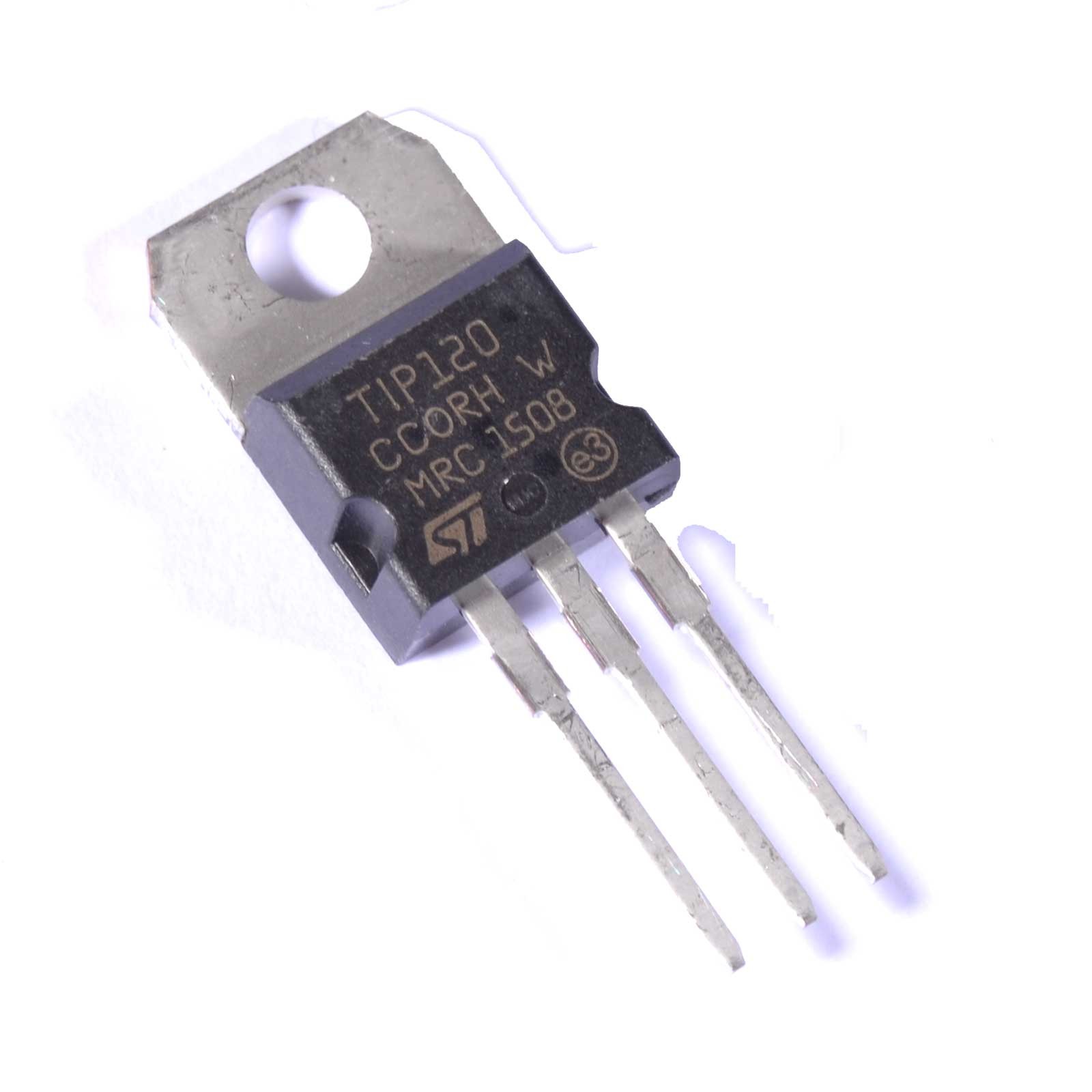
The TIP120 is a high-current, high-voltage Darlington transistor used for switching and amplification applications. It is part of the TIP series of transistors and is well-suited for driving motors, relays, and other high-power loads. The TIP120 features a high current gain and can handle significant power dissipation, making it ideal for use in various electronic circuits requiring robust switching performance.

Key Features:

  • Darlington configuration for high current gain
  • High current handling capability
  • High voltage rating for reliable operation in demanding environments
  • Built-in protection against thermal overload and overcurrent
  • Suitable for use in switching and amplification applications

Technical Specifications:

  • Type: NPN Darlington Transistor
  • Collector-Emitter Voltage (Vceo): 60V
  • Collector-Base Voltage (Vcbo): 60V
  • Emitter-Base Voltage (Vebo): 5V
  • Collector Current (Ic): 5A (maximum)
  • Power Dissipation (Pd): 65W (maximum)
  • Current Gain (hFE): Typically 1000 to 2000 (at Ic = 4A)
  • Gain-Bandwidth Product (fT): 2 MHz (typical)
  • Package Type: TO-220

Applications:

  • Motor and relay drivers
  • High-power switching circuits
  • Amplifiers
  • Solenoid drivers
  • Light dimmers and control systems

Usage:

  1. Mount the TIP120 transistor on a suitable heatsink if high power dissipation is expected.
  2. Connect the base pin to the control signal through a base resistor to limit current.
  3. Connect the collector pin to the load and the emitter pin to ground.
  4. Ensure that the power supply and load are within the transistor’s ratings to avoid damage.
  5. Test the circuit to verify proper operation and adjust the base resistor as needed for the desired switching behavior.

Caution:

  • Ensure proper heatsinking to prevent thermal overload.
  • Verify that the transistor’s voltage and current ratings are not exceeded in your application.
  • Handle with care to avoid damage from static electricity or mechanical stress.

Datasheet:
For detailed technical specifications, refer to the TIP120 Datasheet.

0

TOP

X