Search results for "Resistor

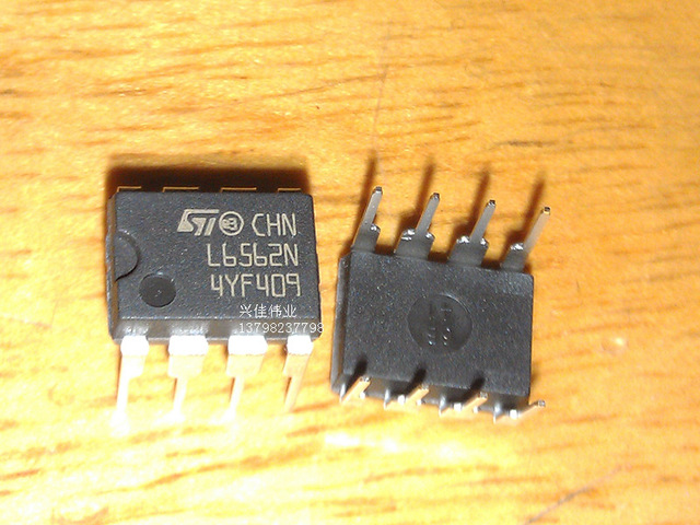
The L6562 is a specialized constant current driver designed for high-efficiency LED lighting applications. It provides a stable current source for driving LEDs with precise control, ensuring consistent brightness and performance. The L6562 integrates several features for reliable operation, including thermal shutdown, overcurrent protection, and a wide operating voltage range.

Key Features:

  • Constant current driver for precise LED control
  • Wide operating voltage range
  • High-efficiency operation with low power dissipation
  • Built-in thermal shutdown and overcurrent protection
  • Adjustable output current for flexibility
  • High-speed switching capability
  • Available in compact packages for easy integration

Technical Specifications:

  • Input Voltage Range: 6V to 45V
  • Output Current: Adjustable, up to 2A (typical)
  • Switching Frequency: Typically up to 100 kHz
  • Thermal Shutdown: Integrated
  • Overcurrent Protection: Integrated
  • Package Type: Available in DIP-8 and surface-mount packages
  • Operating Temperature Range: -40°C to +150°C

Applications:

  • LED drivers for general lighting
  • Automotive LED lighting systems
  • High-brightness LED applications
  • LED strips and modules
  • Outdoor and indoor lighting solutions

Usage:

  1. Connect the input voltage to the appropriate pins of the L6562, ensuring it is within the specified range.
  2. Set the desired output current using external resistors or control signals as described in the datasheet.
  3. Connect the LED load to the output pins and ensure proper heat dissipation.
  4. Monitor the operation and implement thermal management to prevent overheating.

Caution:

  • Ensure that the input voltage and output current are within the specified limits to avoid damage to the IC and connected LEDs.
  • Implement adequate cooling and heat dissipation to maintain reliable operation and prevent thermal shutdown.
  • Follow the datasheet guidelines for external components and circuit design to ensure optimal performance.

Datasheet:
For detailed technical specifications, refer to the L6562 Datasheet.

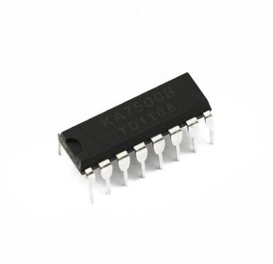
The KA7500 is a versatile power supply controller designed for use in various DC-DC converter and switching power supply applications. It integrates essential functions such as pulse-width modulation (PWM) control, voltage regulation, and protection features to ensure stable and efficient power conversion. The KA7500 is suitable for designing high-performance power supplies with adjustable output voltages and current regulation.

Key Features:

  • Integrated PWM control for efficient power regulation
  • Adjustable output voltage with precise control
  • Built-in voltage reference for stable operation
  • Error amplifier for accurate feedback and regulation
  • High-speed switching capability with minimal external components
  • Built-in protection features including thermal shutdown, overcurrent protection, and undervoltage lockout

Technical Specifications:

  • Input Voltage Range: 8V to 40V
  • Output Voltage Range: Adjustable, based on external components
  • Switching Frequency: Typically up to 100 kHz
  • Voltage Reference: 2.5V ±1% (typical)
  • Error Amplifier Gain: Adjustable
  • Thermal Shutdown: Integrated
  • Overcurrent Protection: Integrated
  • Undervoltage Lockout: Integrated
  • Package Type: Available in DIP-8 and surface-mount packages

Applications:

  • DC-DC converters (buck, boost, and flyback topologies)
  • Switching power supplies for electronic devices
  • Battery chargers and power management systems
  • High-efficiency power converters and inverters
  • Industrial and consumer electronics requiring stable power

Usage:

  1. Connect the input voltage to the KA7500, ensuring it is within the specified range.
  2. Configure the output voltage and other parameters using external resistors and components as described in the datasheet.
  3. Implement the switching frequency and other settings according to your application requirements.
  4. Connect the load to the output and ensure proper heat dissipation and thermal management.

Caution:

  • Ensure that the input voltage and output settings are within the specified limits to prevent damage to the controller.
  • Design and place external components (e.g., inductors, capacitors) carefully to achieve optimal performance and stability.
  • Follow the datasheet recommendations for thermal management and circuit design to maintain reliable operation.

Datasheet:
For detailed technical specifications, refer to the KA7500 Datasheet.

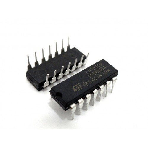
The LM723 is a precision voltage regulator designed to provide stable and reliable voltage regulation in various electronic circuits. This IC offers excellent performance in maintaining a constant output voltage, making it ideal for use in power supplies, voltage reference circuits, and other applications requiring precise voltage control.

Key Features:

  • Precision voltage regulation with high accuracy
  • Adjustable output voltage from 2V to 37V
  • High current output capability
  • Built-in thermal overload protection
  • Short-circuit protection
  • Wide input voltage range
  • Stable operation with external components

Technical Specifications:

  • Package Type: TO-220, TO-3
  • Input Voltage Range: 4V to 40V DC
  • Output Voltage Range: Adjustable from 2V to 37V
  • Output Current: Up to 2.5A
  • Regulation: ±0.1% (typical)
  • Thermal Overload Protection: Yes
  • Short-Circuit Protection: Yes
  • Operating Temperature Range: -40°C to +125°C

Applications:

  • Power supply circuits
  • Voltage reference circuits
  • Regulated power adapters
  • Battery chargers
  • Audio amplifiers

Usage:

  • Configure the LM723 with external resistors and capacitors to set the desired output voltage.
  • Ensure proper heat dissipation with an appropriate heatsink if operating at high currents.
  • Connect the input voltage within the specified range and connect the output as needed for your application.
  • Implement necessary thermal management and ensure proper circuit design to maintain stability.

Caution:

  • Avoid exceeding the maximum input voltage to prevent damage.
  • Ensure proper heat dissipation to avoid overheating.
  • Verify all connections and component values before powering the circuit.

Datasheet: For detailed technical specifications, refer to the LM723 Datasheet.

The HA17555 is a highly stable timer integrated circuit designed by Renesas. It is widely used for precision timing applications, offering monostable and astable operation modes. This versatile IC is ideal for generating accurate time delays, pulse generation, and oscillator applications in a variety of electronic devices.

Key Features:

  • Highly stable timing with precision of 1%
  • Monostable (one-shot) and astable (oscillator) operation modes
  • Adjustable duty cycle in astable mode
  • Capable of producing accurate time delays from microseconds to hours
  • High output current capability
  • Operates from a wide supply voltage range
  • TTL compatible output

Technical Specifications:

  • Package Type: DIP-8 (Dual In-line Package)
  • Operating Voltage: 4.5V to 16V
  • Timing Interval: 0.1 µs to hours (adjustable)
  • Output Current: 200 mA
  • Temperature Stability: 50 ppm/°C
  • Operating Temperature Range: -20°C to +70°C

Applications:

  • Timing delays
  • Pulse generation
  • Sequential timing
  • LED flashers
  • Frequency dividers
  • Signal conditioning

Usage:

  1. Configure the HA17555 in monostable or astable mode depending on the application.
  2. Connect external resistors and capacitors to set the desired timing interval.
  3. Integrate the IC into your circuit design for precision timing tasks.
  4. Ensure proper power supply and signal connections for reliable operation.

Caution:

  • Avoid exposure to moisture and mechanical stress to prevent damage.
  • Verify the supply voltage and timing component values before operation.
  • Follow the manufacturer’s guidelines for circuit design and assembly.

Datasheet:
For detailed technical specifications, refer to the HA17555 Datasheet.

The NTC 10D-9 is a Negative Temperature Coefficient (NTC) thermistor designed for precise temperature measurement and control. Its resistance decreases as temperature increases, making it suitable for various temperature sensing and compensation applications. With its compact size and reliable performance, the NTC 10D-9 is ideal for use in consumer electronics, power supplies, and industrial equipment.

Key Features:

  • Negative Temperature Coefficient (NTC) thermistor
  • High precision and sensitivity
  • Rapid response to temperature changes
  • Compact and robust design
  • Suitable for temperature measurement and compensation
  • Wide operating temperature range

Technical Specifications:

  • Rated Zero Power Resistance @ 25°C: 10Ω ±20%
  • Maximum Steady Current @ 25°C: 2A
  • Residual Resistor at Maximum Steady Current @ 25°C: 0.458Ω
  • B Value (25/50): 2800K ±10%
  • Thermal Time Constant: <32s
  • Heat Dissipation Coefficient: >11mW/°C
  • Operating Temperature Range: -40°C to +175°C
  • Diameter: 9mm

Applications:

  • Temperature sensing
  • Temperature compensation
  • Overcurrent protection
  • Power supply circuits
  • Consumer electronics
  • Industrial equipment

Usage:

  1. Integrate the NTC 10D-9 thermistor into your circuit for accurate temperature sensing or compensation.
  2. Connect the thermistor in series or parallel with other components as required by your application.
  3. Ensure proper calibration for precise temperature measurement.
  4. Monitor the thermistor’s response to temperature changes for optimal performance.

Caution:

  • Handle with care to avoid mechanical stress and damage.
  • Verify the correct resistance and temperature coefficient values for your application.
  • Follow the manufacturer’s guidelines for circuit design and integration.

Datasheet:
For detailed technical specifications, refer to the NTC 10D-9 Datasheet.

The LM1117 is a low dropout voltage regulator available in fixed and adjustable output versions. It is designed to provide an output current of up to 800mA with a dropout voltage of 1V at full load. This regulator is ideal for various applications, including powering low-voltage digital systems, post-regulation of switching supplies, and battery-powered devices.

Key Features:

  • Low Dropout Voltage: 1V at 800mA
  • Output Current: Up to 800mA
  • Fixed and Adjustable Versions: Output voltages of 1.2V, 1.5V, 1.8V, 2.5V, 3.3V, and 5V
  • Thermal Overload Protection: Protects the regulator from overheating
  • Short Circuit Protection: Protects the regulator and the load
  • High-Accuracy Output Voltage: ±1% (fixed version)
  • Low Quiescent Current: Ideal for battery-powered applications

Technical Specifications:

  • Input Voltage Range: Up to 20V
  • Output Voltage Tolerance: ±1% (fixed version)
  • Dropout Voltage: 1V at 800mA
  • Output Current: 800mA
  • Operating Junction Temperature Range: -40°C to +125°C
  • Package Options: SOT-223, TO-220, and TO-263

Applications:

  • Low voltage digital systems
  • Post-regulation for switching supplies
  • Battery-powered devices
  • Portable instruments
  • Motherboards
  • Powering FPGAs, ASICs, and DSPs

Usage:

  1. Connect the input voltage to the input pin of the LM1117.
  2. Connect the output pin to the load.
  3. For the adjustable version, use external resistors to set the desired output voltage.
  4. Ensure proper heat sinking to maintain thermal performance.

Caution:

  • Do not exceed the maximum input voltage to avoid damaging the regulator.
  • Provide adequate heat sinking to prevent thermal shutdown.
  • Avoid short circuits to protect the regulator and load.

Datasheet: For more detailed technical information, refer to the LM1117 Datasheet.

The BC547 is a versatile, general-purpose NPN bipolar junction transistor (BJT) widely used in electronic circuits for switching and amplification purposes. It is commonly found in low-power applications and is known for its reliability and ease of use. The BC547 is suitable for a variety of applications, including signal processing, amplification, and switching.

Key Features:

  • General-Purpose NPN Transistor: Suitable for a wide range of applications
  • Low Power Consumption: Ideal for low-power circuits
  • High Gain: Provides high current gain (hFE)
  • Compact Package: TO-92 package for easy integration into various designs
  • High Reliability: Proven performance in diverse electronic circuits

Technical Specifications:

  • Transistor Type: NPN
  • Collector-Emitter Voltage (VCEO): 45V
  • Collector-Base Voltage (VCBO): 50V
  • Emitter-Base Voltage (VEBO): 6V
  • Collector Current (IC): 100mA
  • Power Dissipation (Ptot): 500mW
  • DC Current Gain (hFE): 110 to 800 (depending on the model)
  • Transition Frequency (fT): 300MHz
  • Package Type: TO-92
  • Operating Temperature Range: -55°C to +150°C

Applications:

  • Signal amplification
  • Switching applications
  • General-purpose amplification
  • Low-noise stages in audio equipment
  • Sensor interfacing
  • Hobby and DIY projects

Usage:

  1. Identify the pin configuration of the transistor: Collector (C), Base (B), and Emitter (E).
  2. Connect the base to the control signal through a suitable current-limiting resistor.
  3. Connect the emitter to ground or negative voltage rail.
  4. Connect the collector to the load or positive voltage rail, depending on the application.
  5. Ensure the power supply voltage and current ratings do not exceed the transistor’s maximum ratings.

Caution:

  • Avoid exceeding the maximum voltage and current ratings to prevent damage to the transistor.
  • Ensure proper heat dissipation if operating near the maximum power dissipation limit.
  • Handle with care to prevent damage from electrostatic discharge (ESD).

Datasheet:
For detailed technical specifications, refer to the BC547 Datasheet.

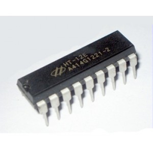
The HT12E is an encoder IC from Holtek Semiconductor designed for remote control applications. It is widely used in wireless communication systems to encode and transmit data over RF or infrared links. The HT12E is compatible with the HT12D decoder IC, making it a popular choice for remote control systems in various consumer electronics, home automation, and security systems.

Key Features:

  • Data Encoding: Encodes 12-bit address and 4-bit data for secure transmission
  • Low Power Consumption: Ideal for battery-operated devices
  • Wide Operating Voltage: Operates from 2.4V to 12V
  • Easy Integration: Compatible with HT12D decoder IC
  • On-Chip Oscillator: Requires minimal external components
  • Multiple Transmission Options: Suitable for RF and infrared communication

Technical Specifications:

  • Operating Voltage: 2.4V to 12V
  • Address Bits: 12
  • Data Bits: 4
  • Oscillator Frequency: Adjustable via external resistor (typically 3kHz to 1MHz)
  • Standby Current: Less than 1µA at 5V
  • Package Type: DIP-18 and SOP-18
  • Operating Temperature Range: -20°C to +70°C

Applications:

  • Remote control systems
  • Home automation
  • Wireless security systems
  • Garage door openers
  • Consumer electronics
  • Toy controllers

Usage:

  1. Configure the 12 address pins to match the address of the corresponding HT12D decoder.
  2. Connect the 4 data pins to the desired input signals.
  3. Connect an appropriate resistor to the oscillator pin to set the desired frequency.
  4. Connect the VT pin to the transmission medium (RF module, infrared LED, etc.).
  5. Apply power to the chip and begin data transmission by changing the states of the data pins.

Caution:

  • Ensure correct power supply voltage to avoid damaging the chip.
  • Match the address pins on the HT12E and HT12D to ensure proper communication.
  • Protect the chip from electrostatic discharge (ESD) during handling.

Datasheet:
For detailed technical specifications, refer to the HT12E Datasheet.

The HT12D is a decoder IC from Holtek Semiconductor designed for remote control applications. It is widely used in wireless communication systems to decode data encoded by the HT12E encoder IC. The HT12D chip is ideal for use in consumer electronics, home automation systems, and security systems, providing a reliable means of wireless data reception and decoding.

Key Features:

  • Data Decoding: Decodes 12-bit address and 4-bit data for secure data reception
  • Low Power Consumption: Ideal for battery-operated devices
  • Wide Operating Voltage: Operates from 2.4V to 12V
  • Easy Integration: Compatible with HT12E encoder IC
  • On-Chip Oscillator: Requires minimal external components
  • Status Indicator: Valid transmission indicator pin (VT)

Technical Specifications:

  • Operating Voltage: 2.4V to 12V
  • Address Bits: 12
  • Data Bits: 4
  • Oscillator Frequency: Adjustable via external resistor (typically 3kHz to 1MHz)
  • Standby Current: Less than 1µA at 5V
  • Package Type: DIP-18 and SOP-18
  • Operating Temperature Range: -20°C to +70°C

Applications:

  • Remote control systems
  • Home automation
  • Wireless security systems
  • Garage door openers
  • Consumer electronics
  • Toy controllers

Usage:

  1. Configure the 12 address pins to match the address of the corresponding HT12E encoder.
  2. Connect the 4 data output pins to the desired control circuits or indicators.
  3. Connect an appropriate resistor to the oscillator pin to set the desired frequency.
  4. Connect the VT pin to an LED or other indicator to show valid data reception.
  5. Apply power to the chip and it will begin decoding data transmitted by the HT12E.

Caution:

  • Ensure correct power supply voltage to avoid damaging the chip.
  • Match the address pins on the HT12D and HT12E to ensure proper communication.
  • Protect the chip from electrostatic discharge (ESD) during handling.

Datasheet:
For detailed technical specifications, refer to the HT12D Datasheet.

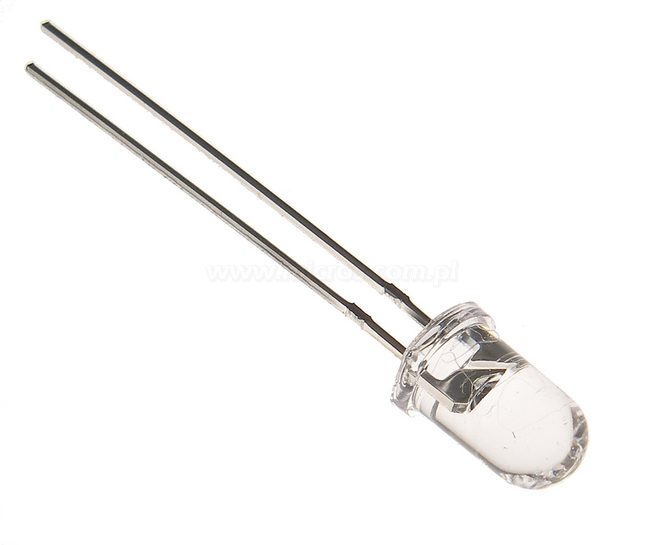
The 5mm blue LED is a versatile and widely used light-emitting diode known for its bright blue light and energy efficiency. This LED is suitable for various applications including indicator lights, displays, and decorative lighting. Its compact 5mm size makes it ideal for use in tight spaces and electronic projects.

Key Features:

  • Emits bright blue light
  • Standard 5mm diameter
  • Low power consumption
  • High brightness and long lifespan
  • Easy to use in various electronic and lighting applications

Technical Specifications:

  • Color: Blue
  • Diameter: 5mm
  • Forward Voltage: 3.0V to 3.5V (typical)
  • Forward Current: 20mA (typical)
  • Luminous Intensity: 5000mcd 
  • Viewing Angle: 20° to 30° (typical)
  • Package Type: Through-hole

Applications:

  • Indicator lights
  • Backlighting for displays
  • Signal and status indicators
  • Decorative lighting
  • DIY electronics projects

Usage:

  1. Insert the LED into the designated holes on a PCB or breadboard.
  2. Ensure correct polarity: the longer lead is the anode (positive), and the shorter lead is the cathode (negative).
  3. Solder the leads to secure the LED in place.
  4. Connect the LED to a suitable current-limiting resistor and power supply.

Caution:

  • Ensure proper polarity to avoid damage.
  • Use a current-limiting resistor to prevent excessive current.
  • Handle with care to avoid physical damage to the LED.
0

TOP

X