- You have no items in your shopping cart
- Subtotal: ₦0.00
Hi guys, this is the first tutorial in a series of tutorials to get beginners up to speed on using the components present in our Arduino kit.To follow this tutorial series, I will advise you grab one of the kits from our store here. Today’s tutorial will focus on the PIR Motion sensor and we will discuss its principle of operation and how to interface it with the Arduino.
Introduction
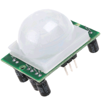
PIR(passive Infrared) Motion sensors allow the easy detection of motion. It is always used to detect if a motion based activity by a warm body has occurred. It is small, low power, cheap and commonly found in Appliances and gadgets used in homes or businesses. It is also referred to as pyroelectric or IR motion Sensor.
Principle Of Operation
For those who are not really interested in the technical part you can skip this section, but I believe you will be able to use the sensor better if you understand how it works.
PIRs are basically made of a pyroelectric sensor (rectangular element in the image below) which is housed in an hermetically sealed round metal can to improve immunity to parameters such as noise, temperature and humidity. There is a window made up of a special IR-transmissible material made of silicon that protects the pyro sensing element.
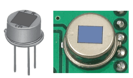
The Pyroelectric sensor itself has two slots in it. Each slot is made up of a special material that is sensitive to IR . When no motion is detected, the two slots detect the same amount of Infrared radiation which is usually the ambient amount of radiation emitted from the walls of the room or the environment. Everything emits some level of radiation so when a warm body like a human or animal passes by, it first intercept one of the slots, this causes a differential change between the slots and its this change, that is detected and recorded as motion taking place.
Connection To Arduino
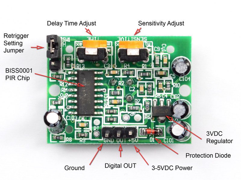
The Motion sensor included in our Arduino kit is a digital sensor and goes high when motion is detected and low when there is no motion. The next section below will teach you how to connect the sensor to the Arduino.
The PIR sensor has a jumper at the back which is used to put the sensor in triggering or non-retriggering mode. The non-triggering mode (jumper to VL), the PIR’s output does not stay high when movement is happening in front of it but actually turns on and off every second or so, but when in retriggering mode(VH), the PIR’s output stays high during the entire duration of the motion.
Required Components
The following components (which are available in the arduino kits are needed for this tutorial;
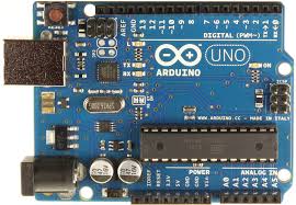
1. Arduino Uno
3. LEDs (Optional)
4. Resistor (Optional)
this components can be bought by clicking on the links attached to them.
Schematics
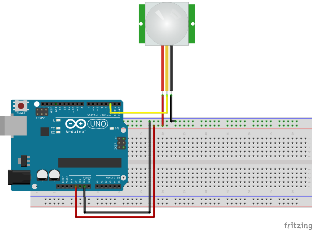
Connect the motion sensor as shown in the Fritzing schematics below.
The arduino has an onboard LED on pin 13 and we will be using it to debug when motion is detected by our system. You can decide to connect an LED to another pin or connect a relay to be triggered when motion is detected. One great application of the relay system will be the turning on/off the light in a room when motion is detected.
Code
With our motion sensor all connected, its time to jump to the code. The code is fairly simple but I will do a quick break down before pasting the full code.
The first thing we did was declare the pins to which our LED and the Motion sensor signal pin will be connected pn the arduino
//Hub360 Circuits (hub360.com.ng)
//Code for interfaacing PIR Motion sensor with Arduino

int led = 13;        // the onboard LED is being used
int PIRpin = 2;      // Pin to which motion sensor is connected
Then we went into the setup function to declare each of them as either output or input depending on the role which they will be paying. The Motion sensor signal pin will be an input while the LED will be an output.
void setup() {
  pinMode(led, OUTPUT);      // setting the LED pin as output
  pinMode(PIRpin, INPUT);    // Setting the PIRpin as input
}
The loop function was next, the first line of code reads the output from the signal pin, and the if statement that follows turns the LED on pin 13 off or on depending on the output of the signal pin.
void loop(){
  int val = digitalRead(PIRpin);
  if (val == HIGH)
  {
    digitalWrite(led, HIGH);
  }
  else
  {
    digitalWrite(led, LOW);
  }
}
The complete code is available below:
//Hub360 Circuits (hub360.com.ng)
//Code for interfaacing PIR Motion sensor with Arduino

int led = 13;        // the onboard LED is being used
int PIRpin = 2;      // Pin to which motion sensor is connected


void setup() {
  pinMode(led, OUTPUT);      // setting the LED pin as output
  pinMode(PIRpin, INPUT);    // Setting the PIRpin as input
}

void loop(){
  int val = digitalRead(PIRpin);
  if (val == HIGH)
  {
    digitalWrite(led, HIGH);
  }
  else
  {
    digitalWrite(led, LOW);
  }
}
Connect the components as described in the schematics, copy this code, past in the arduino IDE and Upload to your board. you should be able to detect motion from then on.
Look Forward
As basic and simple as this example is, there are countless useful project where this comes in handy. the key one for me will be in home automation.
That’s it guys. let me know if you have any questions.


