Search results for "Resistor

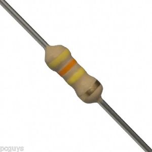
The 51KΩ 1/4W resistor is a precision electronic component designed to provide a fixed resistance value of 51,000 ohms. It is used in various electronic circuits for applications such as voltage dividers, signal conditioning, and current limiting. The resistor has a power rating of 1/4 watt, making it suitable for general-purpose electronics and small signal applications.

Key Features:

  • Fixed resistance value of 51KΩ
  • Power rating of 1/4 watt
  • Axial lead configuration for ease of installation
  • Standard tolerance of ±5%
  • Reliable and accurate performance for electronic circuits

Technical Specifications:

  • Resistance Value: 51KΩ (51,000Ω)
  • Power Rating: 1/4 watt (0.25W)
  • Tolerance: ±5% (standard)
  • Temperature Coefficient: ±100 ppm/°C (typical)
  • Lead Material: Tin-plated copper
  • Body Material: Ceramic or metal oxide

Applications:

  • Voltage dividers
  • Signal conditioning
  • Current limiting
  • Biasing circuits
  • General electronic applications

Usage:

  1. Insert the resistor into the appropriate holes or position on the PCB or breadboard.
  2. Solder the resistor leads to ensure a stable connection.
  3. Check the resistor’s placement and connections before powering the circuit.
  4. Test the circuit to ensure correct functionality.

Caution:

  • Ensure the resistor is used within its rated power to prevent overheating.
  • Verify the resistor’s value with a multimeter for accuracy before installation.
  • Handle the resistor carefully to avoid physical damage.

The 430KΩ 1/4W resistor is a precision electronic component with a resistance value of 430,000 ohms. It is designed for use in various electronic circuits to provide stable and accurate resistance. With a power rating of 1/4 watt, it is suitable for applications that require reliable performance in low-power circuits.

Key Features:

  • Fixed resistance value of 430KΩ
  • Power rating of 1/4 watt
  • Axial lead configuration for easy integration
  • Standard tolerance of ±5%
  • Reliable performance for general electronic applications

Technical Specifications:

  • Resistance Value: 430KΩ (430,000Ω)
  • Power Rating: 1/4 watt (0.25W)
  • Tolerance: ±5% (standard)
  • Temperature Coefficient: ±100 ppm/°C (typical)
  • Lead Material: Tin-plated copper
  • Body Material: Ceramic or metal oxide

Applications:

  • Voltage dividers
  • Signal conditioning
  • Current limiting
  • Biasing circuits
  • General electronic applications

Usage:

  1. Insert the resistor into the designated holes or position on the PCB or breadboard.
  2. Solder the leads of the resistor to ensure a secure connection.
  3. Verify the placement and soldering of the resistor before powering up the circuit.
  4. Test the circuit to ensure proper functionality.

Caution:

  • Avoid exceeding the resistor’s power rating to prevent damage or overheating.
  • Check the resistor’s value with a multimeter before installation to ensure accuracy.
  • Handle the resistor carefully to prevent physical damage.

The 4.7Ω 1/4W resistor is a low-value precision resistor used in electronic circuits for current limiting, voltage division, and signal conditioning. With a resistance of 4.7 ohms and a power rating of 1/4 watt, it is suitable for low-power applications where precise resistance is required.

Key Features:

  • Fixed resistance value of 4.7Ω
  • Power rating of 1/4 watt (0.25W)
  • Axial lead configuration for easy integration
  • Standard tolerance of ±5%
  • Reliable performance for general electronic applications

Technical Specifications:

  • Resistance Value: 4.7Ω
  • Power Rating: 1/4 watt (0.25W)
  • Tolerance: ±5% (standard)
  • Temperature Coefficient: ±100 ppm/°C (typical)
  • Lead Material: Tin-plated copper
  • Body Material: Ceramic or metal oxide

Applications:

  • Current limiting in LED circuits
  • Voltage dividers
  • Pull-up/pull-down resistors
  • Signal conditioning
  • General electronic circuits

Usage:

  1. Insert the resistor into the designated holes or position on the PCB or breadboard.
  2. Solder the leads of the resistor to ensure a secure connection.
  3. Verify the placement and soldering of the resistor before powering up the circuit.
  4. Test the circuit to ensure proper functionality.

Caution:

  • Avoid exceeding the resistor’s power rating to prevent damage or overheating.
  • Check the resistor’s value with a multimeter before installation to ensure accuracy.
  • Handle the resistor carefully to prevent physical damage.

The 3.7Ω 1/4W resistor is a precision component used in various electronic circuits for applications requiring specific resistance values. It is designed to handle low power levels and provides accurate resistance for tasks such as current limiting, voltage division, and signal processing.

Key Features:

  • Fixed resistance value of 3.7Ω
  • Power rating of 1/4 watt (0.25W)
  • Axial lead configuration for easy mounting
  • Standard tolerance of ±5%
  • Reliable performance in low-power electronic circuits

Technical Specifications:

  • Resistance Value: 3.7Ω
  • Power Rating: 1/4 watt (0.25W)
  • Tolerance: ±5% (standard)
  • Temperature Coefficient: ±100 ppm/°C (typical)
  • Lead Material: Tin-plated copper
  • Body Material: Ceramic or metal oxide

Applications:

  • Current limiting in electronic circuits
  • Voltage divider networks
  • Pull-up/pull-down resistor configurations
  • Signal conditioning in circuits
  • General-purpose electronics

Usage:

  1. Insert the resistor into the appropriate holes or position on a PCB or breadboard.
  2. Solder the leads of the resistor to establish a secure connection.
  3. Ensure correct placement and soldering before powering up the circuit.
  4. Verify circuit functionality after installation.

Caution:

  • Do not exceed the resistor’s power rating to avoid overheating or damage.
  • Measure the resistor’s value with a multimeter before installation to ensure it matches specifications.
  • Handle the resistor with care to prevent physical damage.

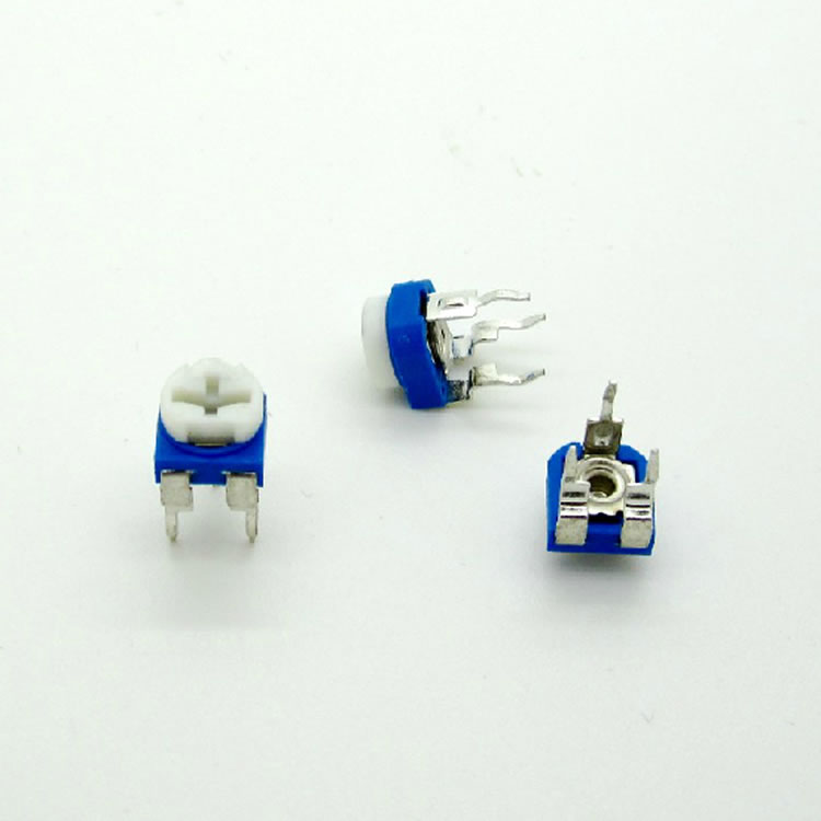
The 100KΩ Variable Resistor, also known as a potentiometer, is a component used to adjust resistance within an electronic circuit. With a maximum resistance of 100 kilohms, it allows for fine-tuning and calibration of circuits by varying resistance to achieve the desired electrical characteristics. This component is commonly used in applications such as volume controls, signal processing, and tuning circuits.

Key Features:

  • Resistance Range: 100KΩ (100,000Ω)
  • Adjustable resistance for fine-tuning and calibration
  • Available in rotary or linear adjustment types
  • Typically available in through-hole or surface-mount packages

Technical Specifications:

  • Resistance Value: 100KΩ (100,000Ω)
  • Tolerance: ±10%
  • Power Rating: Usually 0.5W to 1W
  • Adjustment Type: Rotary or linear 
  • Package Type: Through-hole 

Applications:

  • Audio and volume control in electronic devices
  • Calibration and adjustment in measurement systems
  • Signal attenuation and gain control in analog circuits
  • Tuning and fine adjustment in various electronic applications

Usage:

  1. Integrate the potentiometer into the circuit as per the design requirements.
  2. Adjust the resistance by rotating or sliding the control to the desired value.
  3. Confirm the adjustment through circuit testing to ensure it meets the operational needs.

Caution:

  • Ensure the potentiometer’s power rating is not exceeded to avoid overheating.
  • Handle with care to prevent damage to the mechanical adjustment mechanism.
  • Regularly check and calibrate if used frequently in sensitive applications.

The 50KΩ Variable Resistor, also known as a potentiometer, is an electronic component that allows for the adjustment of resistance within a circuit. It provides a variable resistance range of up to 50 kilohms, enabling precise control over electrical signals and voltages in various electronic applications. This component is commonly used in settings such as volume controls, tuning circuits, and calibration systems.

Key Features:

  • Resistance Range: 50KΩ (50,000Ω)
  • Adjustable resistance for fine-tuning and calibration
  • Available in rotary or linear adjustment types
  • Typically offered in through-hole or surface-mount designs

Technical Specifications:

  • Resistance Value: 50KΩ (50,000Ω)
  • Tolerance: ±10%
  • Power Rating: Typically 0.5W to 1W
  • Adjustment Type: Rotary or linear 
  • Package Type: Through-hole

Applications:

  • Audio volume control
  • Signal attenuation and gain control
  • Calibration and adjustment in measurement systems
  • Fine-tuning in analog circuits

Usage:

  1. Incorporate the potentiometer into the circuit as per design specifications.
  2. Adjust the resistance by rotating or sliding the control to the desired level.
  3. Verify the adjustment through circuit testing to ensure proper operation.

Caution:

  • Avoid exceeding the potentiometer’s power rating to prevent overheating.
  • Handle the component carefully to avoid damaging the adjustment mechanism.
  • Regularly check and recalibrate in sensitive or frequently adjusted applications.

The 20KΩ Variable Resistor, also known as a potentiometer, is a component used to adjust resistance within electronic circuits. It provides a variable resistance range of up to 20 kilohms, enabling precise control over electrical signals and voltages. This component is commonly employed in applications such as volume controls, tuning circuits, and calibration systems.

Key Features:

  • Resistance Range: 20KΩ (20,000Ω)
  • Adjustable resistance for fine-tuning and calibration
  • Available in rotary or linear adjustment types
  • Typically offered in through-hole or surface-mount designs

Technical Specifications:

  • Resistance Value: 20KΩ (20,000Ω)
  • Tolerance: ±10% 
  • Power Rating: Typically 0.5W to 1W
  • Adjustment Type: Rotary or linear
  • Package Type: Through-hole

Applications:

  • Audio volume control
  • Signal attenuation and gain control
  • Calibration and adjustment in measurement systems
  • Fine-tuning in analog circuits

Usage:

  1. Incorporate the potentiometer into the circuit according to design specifications.
  2. Adjust the resistance by rotating or sliding the control to the desired level.
  3. Verify the adjustment through circuit testing to ensure proper operation.

Caution:

  • Do not exceed the potentiometer’s power rating to avoid overheating.
  • Handle the component carefully to prevent damage to the adjustment mechanism.
  • Regularly check and recalibrate in sensitive or frequently adjusted applications.

The 10KΩ Variable Resistor, also known as a potentiometer, is a crucial electronic component used to adjust and control resistance in a circuit. With a resistance range of up to 10 kilohms, it allows for precise adjustments of voltage and current in various applications. This component is widely utilized in volume controls, tuning circuits, and other calibration systems.

Key Features:

  • Resistance Range: 10KΩ (10,000Ω)
  • Adjustable resistance for accurate control
  • Available in rotary or linear adjustment types
  • Offered in through-hole or surface-mount designs

Technical Specifications:

  • Resistance Value: 10KΩ (10,000Ω)
  • Tolerance: ±10%
  • Power Rating: Typically 0.5W to 1W
  • Adjustment Type: Rotary or linear
  • Package Type: Through-hole

Applications:

  • Audio volume adjustment
  • Signal attenuation and gain control
  • Calibration in measurement devices
  • Fine-tuning in analog circuits

Usage:

  1. Connect the potentiometer to the circuit as per the design specifications.
  2. Adjust the resistance by rotating or sliding the control to the desired level.
  3. Test the circuit to ensure the adjustment meets operational requirements.

Caution:

  • Avoid exceeding the potentiometer’s power rating to prevent overheating.
  • Handle with care to avoid damaging the adjustment mechanism.
  • Regular recalibration may be needed in applications requiring precise adjustments.

The 1KΩ Variable Resistor, also known as a potentiometer, is an essential component for adjusting resistance in electronic circuits. It provides a variable resistance value up to 1 kilohm, allowing for fine-tuning of voltage and current levels. This resistor is commonly used in applications requiring precise control, such as volume adjustment, signal calibration, and other variable resistance needs.

Key Features:

  • Resistance Range: 1KΩ (1,000Ω)
  • Adjustable for precise control of resistance
  • Available in rotary or linear adjustment types
  • Can be found in through-hole or surface-mount packages

Technical Specifications:

  • Resistance Value: 1KΩ (1,000Ω)
  • Tolerance: ±10%
  • Power Rating: Typically 0.5W to 1W
  • Adjustment Type: Rotary or linear
  • Package Type: Through-hole 

Applications:

  • Audio volume control
  • Signal level adjustment
  • Calibration in measurement systems
  • Fine-tuning in analog electronic circuits

Usage:

  1. Integrate the potentiometer into the circuit according to design requirements.
  2. Adjust the resistance by rotating or sliding the control to achieve the desired resistance.
  3. Verify the circuit’s performance to ensure it meets operational specifications.

Caution:

  • Do not exceed the potentiometer’s power rating to avoid overheating.
  • Handle with care to prevent damage to the adjustment mechanism.
  • Regular checks may be necessary to ensure accurate resistance values over time.

The 1MΩ Variable Resistor, commonly known as a potentiometer, is used to adjust resistance values in electronic circuits. With a maximum resistance of 1 megohm (1,000,000Ω), this component allows for precise control and calibration in various applications. It is often used for fine-tuning signal levels, voltage settings, and calibration tasks in electronic devices.

Key Features:

  • Resistance Range: 1MΩ (1,000,000Ω)
  • Variable adjustment for precise control
  • Available in rotary or linear adjustment types
  • Can be found in through-hole or surface-mount packages

Technical Specifications:

  • Resistance Value: 1MΩ (1,000,000Ω)
  • Tolerance: ±10% 
  • Power Rating: Typically 0.5W to 1W 
  • Adjustment Type: Rotary or linear 
  • Package Type: Through-hole

Applications:

  • High-impedance signal adjustment
  • Calibration in high-impedance measurement systems
  • Voltage divider circuits
  • Fine-tuning in analog electronic circuits

Usage:

  1. Integrate the potentiometer into the circuit according to design requirements.
  2. Adjust the resistance by rotating or sliding the control to achieve the desired resistance.
  3. Verify the circuit’s performance to ensure it meets operational specifications.

Caution:

  • Do not exceed the potentiometer’s power rating to avoid overheating.
  • Handle with care to prevent damage to the adjustment mechanism.
  • Regular checks may be necessary to ensure accurate resistance values over time.
0

TOP

X