Extraordinary FF433 20KM drone Remote control Range Extender

Extraordinary FF433 20KM drone Remote control Range Extender

90,000.00

In stock

SKU: 2344 Categories: ,

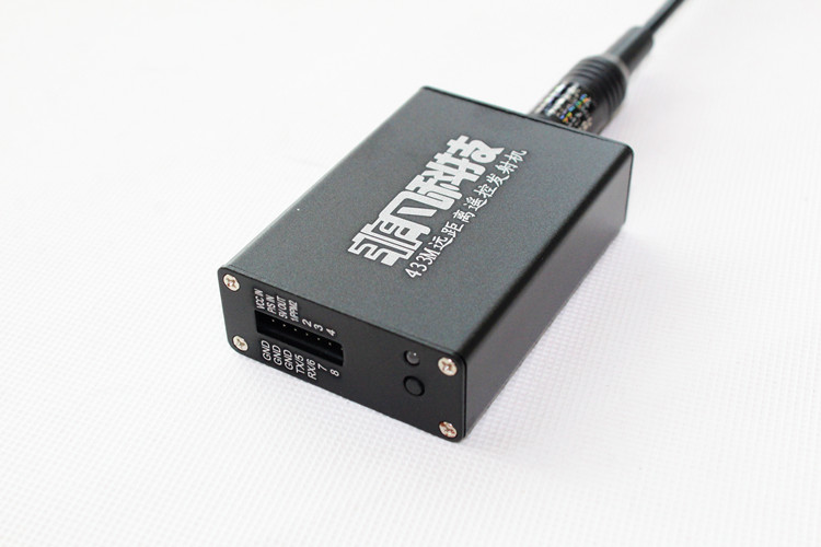
Extraordinary FF433-TX2 remote control signal transmission repeater function button instructions

Hardware version Ver: FF433-TX2 Firmware version: V1.8 (hereinafter referred to as TX2)

Note: TX2 must be connected to the signal normally (the blue light is on in the standby state) before it can enter the linking frequency or set the runaway protection mode

(1) The method of linking with the transmitter in the TX2 relay mode: press and hold the button of the transmitter release it when the blue light flashes, and then power on the TX2 (the blue light of the transmitter stops flashing, the linking is successful)
(2) How to link the receiver to TX2: press and hold the TX2 button, release it when the blue light flashes, and then power on the receiver (the TX2 blue light stops flashing, that means the pairing is successful)
(3) The receiver fail-safe setting method: First, set each channel of the remote control to the amount of rudder you want the receiver to output when it is out of control, then press and hold the TX2 button, and release it when the red light flashes. then to the receiver is energized (TX2 red lights stop flashing that is set up, Note: the receiver must be good after TX2 of frequency can be set failsafe )
(4) upgrade mode entry method: Hold down the button does not TX2 in case of power failure Put it on,and then power it on again. If you see theredindicator light flashing quickly, it means you have entered the upgrade mode.
(5) TX2 setting method:Press the button N times in standby mode to enter the corresponding function setting.

For example, if we want tosetthe transmitter power to (1500MW), we need to press the function key 3 times and then flash 3 times purple light ( red and blue while lighter color ) ( purple lights number flash representative of the number of times you pressed), then into the red light or blue light flashes (such as intermittent flashing 4 red light to indicate the current power is 2000MW), to change When the power is pressed 3 times , the blue light will flash 3 times (1500MW) intermittently
Function table use video tutorial https://v.youku.com/v_show/id_XNjU0MzkyNzg4.html

To save the current settings press the function key 1 second or more, the red and blue lights flashing alternately description saved successfully twice, and then restart automatically enters the standby state

(All settings will be stored permanently, unless manually restored to factory settings or reset) The following is the function table

Press continuously

Key times

Menu entered

Light flashes

Frequency and color

Corresponding function Detailed remarks
1 Voltage broadcast no Announce the current voltage value The number of long beeps of the buzzer indicates the single place value of the
voltage. The number of short beeps of the buzzer indicates the decimal value of the voltage.
For example: 11.7V will be long, 1 short beep, 7 beeps,
12.4V will be 
long, 2 beeps, 4 beeps,
10.5V, will be long 0 beeps, 5 beeps, short beeps
2 Signal input mode selection Red light 1 time Repeater mode Before the signal is relayed through the wireless input , it needs to be paired with the transmitter to be relayed.
When the repeater receives the signal from the transmitter, it will transmit the signal with high power intact
to expand the remote control range. And the 1-8 channel data of this signal will output the PWM signal through the “PWM1-PWM8” port
Blue light 1 time
(default)
Transmitter mode 1 Single-channel signal input mode
SBUS or PPM or PWM input mode
(3 kinds of signals are automatically recognized) If the input is S.UBS signal, it can directly include 16 channels (if 16 channels are required, please set the “number of channels” to 16 channels) (need to re- link after setting)
Blue light 2 times Transmitter mode 2 Dual-channel signal input mode
PPM or SBUS of the remote controller is input from “P/S IN” , and the PPM signal of the head tracking is input from the “1/PPM2” port
(the channel of PPM2 is automatically recognized)
General head tracking input can be selected in this mode
( If this mode does not recognize the PPM2 channel normally, please select the following dual-signal input mode)
Blue light 3 times Transmitter mode 3

Dual signal input mode
1-8 channels are obtained from P/S IN, 9-16 channels are obtained from PPM2

(if 16 channels are required, please set the “number of channels” to 16 channels) (re- linking is
required after setting)

Blue light 4 times Transmitter mode 4

Dual signal input mode
1-8 channels are obtained from P/S IN, 9-16 channels are obtained from PPM2

(if 16 channels are required, please set the “number of channels” to 16 channels) (re- linking is
required after setting)

Blue light 5 times Transmitter mode 5 Dual signal input mode
1-8 channels are
 input from P/S IN, 9-16 channels are input from PWM1-PWM8 ports
(if 16 channels are required, please set the “number of channels” to 16 channels)
(re-check after setting frequency)
3 Transmit power adjustment Blue light 1 time 500MW (0.5W) After increasing the power, the transmission distance will increase , and the heat generated by the transmitter will increase.
Blue light 2 times 1000MW (1.0W)
Blue light 3 times 1500MW (1.5W)
Red light 4 times
(default)
2000MW (2.0W)
4 Restore factory default settings Red light once
(default)
Restore the machine to
factory default settings
After the factory reset all settings are reset to default settings
(after restore default settings need to re-pair frequency)
Receiver
output mode
setting
Blue light
1-6 times
Receiver output mode This 6 is disposed a receiver output mode , press and then provided to the transmitter mode corresponding pressbutton to save, when a transmission opportunity by flash purple light ( red and blue while color light ) enters the frequency mode, and then feeding the receiver , The transmitter will send the set parameters to the receiver, and the transmitter indicator will stop flashing after the setting is successful.
(For specific descriptions of each output mode, please refer to the corresponding receiver function table)
5 Channel number
setting
Blue light once
(default)
8 channels The number of remote control channels sent by the transmitter to the receiver
(the less the number of channels, the longer the communication distance will be)
more than 8 channels can be directly included in the S.BUS of a receiver 16 channels; it can also be used in conjunction with 2 receivers, Set any one of the receivers to output 1-8 channels, and the other receiver to output 9-16 channels
(the two receivers can be set and run independently without affecting each other)
(transmitter mode function, after setting it is required Re-pair)
Red light 2 times 12 channels
Red light 3 times 16 channels
6 Wireless communication rate setting Red light once
(default)
9600bps The smaller the speed, the longer the distance,
but when the remote control is too small, the steering gear will not be very smooth
(generally the output of the remote control will not exceed 50HZ, except for high-speed SUBS, unless a smoother feel is required for playing helicopters, it is generally not recommended More than 19200bps) (Transmitter mode function, need to re- link
after setting)
Blue light 2 times 19200bps
Red light 3 times 57600bps
7 Low voltage alarm value setting Red light 1 time Turn off low voltage alarm The alarm voltage value set here is the voltage value of a single cell.
For example: set to 3.6V alarm,
if 3S power supply is used, the alarm voltage is 10.8V (3.6V * 3)
If 6S power supply is used, the alarm voltage is 21.6V ( 3.6V * 6)
When the supply voltage is less than or equal to the set voltage, the
buzzer will alarm once every 20 seconds
Blue light 1 time 3.1V
Blue light 2 times 3.2V
Blue light 3 times 3.3V
Blue light 4 times 3.4V
Blue light 5 times 3.5V
Blue light 6 times 3.6V
Blue light 7 times
(default)
3.7V
Blue light 8 times 3.8V
8 Voltage calibration Red light once
(default)
Exit without calibration Note: 3S battery power supply must be used during voltage calibration (2S-6S power supply can be used after calibration is completed).
First measure the actual voltage of the battery, then set it to the corresponding voltage value according to the list, and press and hold the button to save and exit.
For example: the actual voltage measured is 11.5V, just set the blue light to flash 5 times,
then press and hold the button to save and exit.
Blue light 1 time 11.1V
Blue light 2 times 11.2V
Blue light 3 times 11.3V
Blue light 4 times 11.4V
Blue light 5 times 11.5V
Blue light 6 times 11.6V
Blue light 7 times 11.7V
Blue light 8 times 11.8V
Blue light 9 times 11.9V
Blue light 10 times 12.0V
Blue light 11 times 12.1V
Blue light 12 times 12.2V
Blue light 13 times 12.3V
Blue light 14 times 12.4V
Blue light 15 times 12.5V
Blue light 16 times 12.6V


Extraordinary FF433-RX2 433 remote control signal receiver

Hardware version Ver: FF433-RX2 Firmware version: V1.8

Note: The transmitter must be connected to the signal normally (the blue light is on in the standby state) before it can enter the linking frequency or set the runaway protection mode

(1) The method of linking the receiver and the transmitter: press and hold the button of the transmitter , release it when the blue light flashes, and then power on the receiver (the blue light of the transmitter stops flashing, the linking is successful)
(2) Receiver runaway protection setting method: First dial each channel of the remote control to the amount of rudder you want the receiver to output when it loses control, then press and hold the transmitter button, and release it when the red light flashes. , And then power on the receiver (the transmitter’s red light stops flashing, the setting is successful. Note: The receiver must be frequency-aligned with the transmitter before setting the fail-safe protection )
(3) The method for restoring the receiver to factory settings: the receiver is powering off 8 short-channel case channel and the signal line 10 , and power to the receiver, see the lightof redand bluealternating flashes if successful recovery. (After restoring the default settings, you need to re-link with the transmitter)
(4) The receiver enters the upgrade mode method: short -circuit the 9-channel and 10-channel signal lines when the receiver is powered off, and then power on the receiver and seeredThe indicator light flashes quickly, indicating that it has entered the upgrade mode.

Video tutorialhttps://v.youku.com/v_show/id_XMTczMDc4NTIyMA==.html

(All settings will be stored permanently, unless manually restored to factory settings or reset) The following is the function table

transmitter

Press continuously

Key times

Menu entered

transmitter

Light flashes

Frequency and color

Corresponding function Detailed remarks
4 Receiver
output mode
setting
Blue light 1 time
(default)
Receiver’s 1-8 channels output PWM, 9 channels output RSSI, 10 channels output PPM This 6 is disposed a receiver output mode , press and then provided to the transmitter mode corresponding pressbutton to save, when a transmission opportunity by flash purple light ( red and blue while color light ) enters the frequency mode, and then feeding the receiver , The transmitter will send the set parameters to the receiver, and the transmitter indicator will stop flashing after the setting is successful.
Note: When the blue light is 3 times , the 8th channel of the 9-channel output PPM and the 10-channel output S.BUS signal will output RSSI. (RSSI output value is 1ms-2ms)
When 9 channels are set to output RSSI, the output RSSI signal is voltage type, the range is 0-3.3V
Blue light 2 times PWM output of the receiver channels 1-8, 9 pass channel output RSSI, 10 channel output S.BUS
Blue light 3 times The receiver’s 1-8 channels output PWM, 9 channels output PPM, 10 channels output S.BUS
Blue light 4 times All channels 1-10 of the receiver output PWM
Blue light 5 times Receiver’s 1-8 channels output 9-16 channels of PWM, 9 channels output RSSI, 10 channels output PPM
Blue light 6 times The 1-8 channels of the receiver output 9-16 channels of PWM, 9 channels output RSSI, and 10 channels output S.BUS

Additional Information

Weight 0.133 kg

Reviews

There are no reviews yet.

Be the first to review “Extraordinary FF433 20KM drone Remote control Range Extender”

0

TOP

X