KK 2.1.5 VTOL Flight Controller

KK 2.1.5 VTOL Flight Controller

37,800.00

In stock

SKU: 2319 Category:
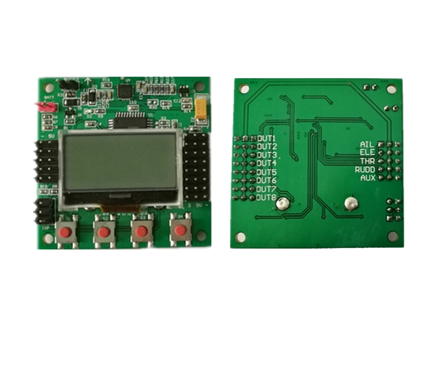
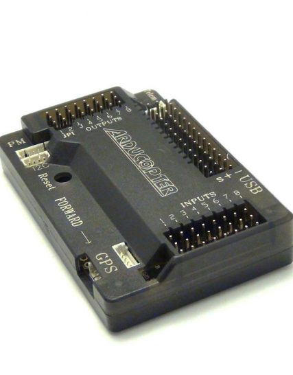
KK2.15 multi-rotor flight control board:
Size: 51mm x 51mm x 12mm
Weight: 19 g 
Manifold: Atmega
Top: InvenSense Inc.
Accelerometer: Anologue Devices Inc.
Self-balancing function: Yes
Input voltage: 4.8-6.0V
Signal from receiver: 1520us (5 channels in total)
Signal sent to ESC (steering gear): 1520us
Firmware version: V1.17S1PRO
Built-flight mode type:
Double rotor
Tri-rotor
Y6
Four axis +
Four axis X
Six axis +
Six axis X
Eight axis +
Eight axis X
X8 +
X8 X
H8
H6
V8
V6
Aero 1S Aileron
Aero 2S Aileron
Flying wing
Single axis 2M 2S
Single axis 1M 4S
V tail four axis
 All settings and adjustments are carried out through the LCD screen and the four buttons below, no computer is required. Unless it is to upgrade the firmware.
All the items contained in this product are as follows:
KK2.15 itself has a self-balancing mode. In this mode, when the transmitter stick is released when tilting in the air, the aircraft will automatically return to the level. In the old version of the firmware, this mode must be entered by flipping the fifth channel switch. , Which means that you either fly in aerobatic mode or fly in self-balance mode. The great thing about 1.6++ is that it combines these two modes. When the joystick is near the neutral position, it is the self-balancing mode. When the joystick has a large amount of movement, it is the stunt mode, and there is no need to rush the switch anymore!
Note: The left and right wirings are all white signal wires facing the LCD screen, and black ground wires facing the outside of the board. Do not connect them wrong!
      

In addition, the “BUZZER” in the upper left corner is connected to a loud buzzer. After connecting, you can make the boot and key sounds deafening. It is mainly used when a low pressure alarm, but for a low pressure warning, but also on the board soldering line, and then set the warning voltage and the battery voltage in the software! 
The KK2.15 flight controller is only powered by the first output socket (M1) in the upper right corner, so when you get the board, please connect an ESC or UBEC to M1 (note that the signal wire is to the LCD screen, and the ground wire is to the edge of the board! Do not connect to high voltage, otherwise the board will burn out instantly and cannot be used.)
1. Wiring

There are 5 sockets on the left, connected to the receiver, from top to bottom: aileron, elevator, throttle, direction, and additional switch channels.
A maximum of 8 motors can be connected from top to bottom on the right side, so it can support up to eight rotors.
Note that the left and right wirings are all white signal wires facing the LCD screen, and the black ground wires facing the outside of the board. Do not connect wrongly.
 
Because only M1 supplies power to the flight controller, an ESC must be connected here. The positive and negative poles of M2 to M8 are connected in parallel, and the ESC here can supply power to the steering gear. You can connect multiple “linear” BECs, don’t connect multiple “switch” BECs.
 
! ! ! Do not install propellers! ! !
2. Receiver signal test.
Enter ” Receiver Test ” from the main menu and move each lever on the transmitter to ensure that the movement direction displayed on the LCD is consistent with the joystick. I think you always know Left Right, Up Down. . If there is a reverse direction, set the reverse direction on the transmitter.
Including the fifth channel switch, if you have a three-way switch, according to your own habits, the up or down is the stunt mode and the self-balance mode, the middle position is the “lost alarm” mode, if your aircraft falls into the grass and can’t be found, You can dial to this position and the buzzer will make a loud noise. . . The premise is that you installed that loud volume. . .
When the pole is in the neutral position, the LCD display must be 0, if not, please use the sub trim function on the transmitter to set it.
The picture below shows “No Signal” because I did not connect the receiver, so there is no signal.


3. Set the multi-axis mode.
The remote control creates a new model and selects the normal fixed-wing aircraft mode.
Press the DOWN button to Load Motor Layout, press ENTER to enter the multi-axis mode selection
It can be seen that there are countless multi-axis modes supported by KK2.15. . .
Finally: V tail!

Select the multi-axis rack mode you want here, and press ENTER to confirm. The screen will display the currently selected mode, which position the motor is at, and the direction of rotation of the propeller! 

Under “Show Motor Layout” in the main menu, you can also see which rack mode it is currently in and the direction of motor rotation. Very convenient and intuitive.


4. ESC calibration and propeller direction setting.
! ! ! Do not install propellers! ! !
ESC calibration process  (no need to turn on the transmitter!):

  1. Remove all the propellers, but the three wires between the motor and the ESC must be connected, otherwise you will not hear any movement!
  2. It is best to pull out all the servos from the flight controller. Because some servos can’t withstand excessive signal changes.
  3. Press and hold any button except the leftmost button, and then connect the power.
  4. Continue to hold down the button until you hear the alarm sound of the motor at the highest position of the throttle and release it immediately.
  5. After waiting for a few seconds, after the motor and ESC stop sounding, press’EXIT’ to return to the SAFE main screen.
If the above is unsuccessful, you can also directly connect the ESC through the receiver throttle channel and calibrate one by one.
Put the throttle at the lowest position, and hold the rudder to the right for a few seconds. At this time, the main screen will change from SAFE to ARM. Gently move the throttle a little, and each motor should start to rotate at the same time.
Observe the motor rotation direction. If it is different from the motor rotation direction shown in the “Show Motor Layout” mentioned above, change any two wires between the ESC and the motor.
Note that at any time you start the aircraft, you must first lower the throttle to the lowest, and turn the rudder to the left for a few seconds, and then move the SAFE screen.
5. Accelerometer calibration.
Place the aircraft on an absolutely level surface, preferably using a bubble level. Enter ACC Calibration from the main menu and proceed to the next step according to the instructions on the screen.
This step only needs to be done once.
6. Sensitivity.

The second item of the main menu is “PI Sensitivity Editor” PI Editor. Press DOWN to reach this item and then press ENTER to enter the following interface:
When the cursor is behind Axis, you can press CHANGE to change which axis to set (roll, pitch, spin). Press NEXT or PREV to move the cursor to the number to change the value. By default, the roll and pitch settings are related, if you modify one of them, the other will change accordingly.
Here I will give you a brief introduction. All PI adjustments of flight controllers have similar meanings. You can find a lot of information. Generally, first adjust I Gain to 0, and then increase P Gain as much as possible, until the aircraft begins to “jitter” at high frequencies when hovering, and then lower P a little bit to stop it. Then increase I until the aircraft starts to “shake” (lower frequency than “shake”) when hovering, then lower I a little bit to stop it.
P Limit and I Limit can be ignored, just keep the default values.
The following default settings can be used for the first flight:

Roll/Pitch Axis:
Pgain = 150 Plimit = 100

Igain = 50 Ilimit = 20

Yaw Axis:

Pgain = 150 Plimit = 20

Igain = 50 Ilimit = 10 

7. Set the flight mode switch.
Enter “Mode Settings” from the main menu. There is ” SL Stick Mixing “, you can choose LOW, MEDIUM or HIGH. This means that in the “Pole back to center auto balance” mode, how quickly it will be automatically balanced after centering, the higher the faster, the faster. It is recommended to use Medium to experience it before adjusting.
After setting, flip the fifth channel switch, different modes will be displayed behind Self-Level under SAFE on the main screen.

8. Test flight!

Install the propeller, turn the fifth channel switch, and ensure that the SAFE screen displays Self-Leve: OFF: first adjust the unbalanced mode.
Reach the bottom of the throttle, turn the rudder to the far right for a few seconds, and the screen displays ARM. Push the throttle slightly and observe the direction of the aircraft movement after the propeller rotates. If there is any abnormality in the axial direction and the movement becomes more and more intensified, immediately refuel, land, and hit the rudder to the far left and return to the SAFE interface.
It should be the correct direction of a certain channel. You can enter the channel through the Mix Editor menu to make settings.
Take my V-tail four-axis as an example, currently channel 4 is set. This interface shows how the fourth channel works when the remote control sends commands.
Throttle: 120. When there is a throttle command, the motor of this channel will rotate at 120% of the command. Because my tail motor is one size smaller than the previous two motors, I set 120 here, and the first two are 100. If you find that the aircraft is flying forward when you push the throttle to speed up, then the 120 is too big.
Aileron:0, when there is an aileron command, the motor will remain unchanged.
Elevator: -90, the speed of the tail motor speed can make the aircraft pitch changes, so when there is an elevator command, here is -90.
Rudder: 100, the speed of the two tail motors of the V tail also makes the aircraft spin and steer, so when there is a rudder command, here is 100. On my three-axis, this number used to be -100, and the positive or negative of the value can cause the movement to be reversed.
Offset: -10, if there is a slow offset movement of a certain axis when hovering, adjust it here. My V-tail will slowly rotate to the left when hovering. I modified this and it’s fine.


When everything is normal and you can fly, adjust PI sensitivity again. . . take it easy.
9. After adjusting the non-self-balance mode, you can try the self-balance mode.
After taking off in the self-balancing mode, the level should not flutter under no wind conditions. If there is flutter, enter the Self-level settings to modify it.
 The self-balance mode also has sensitivity that can be adjusted.
10. Aerobatics.
In the self-balancing mode of V1.6++, it is actually “joystick back to center self-balancing”, that is, when the amount of joystick is large, it is in the trick mode. You can test it now, hover to a certain height, slam the joystick to the maximum, and see if the airplane is running fast, then immediately release the joystick, and the airplane should automatically return to level immediately. But you will find that the plane will not “turn over” when the joystick is maximized. .
This is because there is a “stick ratio” Stick Scaling setting value is very low, you see the default is 30:

You can enter the Stick Scaling interface from the main menu, try one channel by channel, and increase the value. For my 3-axis and V-tail, when the value reaches 100, I fly to a height of 10 meters or more, hit the maximum pole, and roll at a speed to ensure that it will not fall to the ground. The larger the number, the faster the roll.
But you will find that after this number is large, the plane will move violently if you move a little rod, which is difficult for thieves to control. At this time, you can set the EXPO curve of each channel on the transmitter, so that when the joystick is near the neutral position, the output is relatively smooth.

Additional Information

Weight 0.037 kg

Reviews

There are no reviews yet.

Be the first to review “KK 2.1.5 VTOL Flight Controller”

0

TOP

X