- You have no items in your shopping cart
- Subtotal: ₦0.00
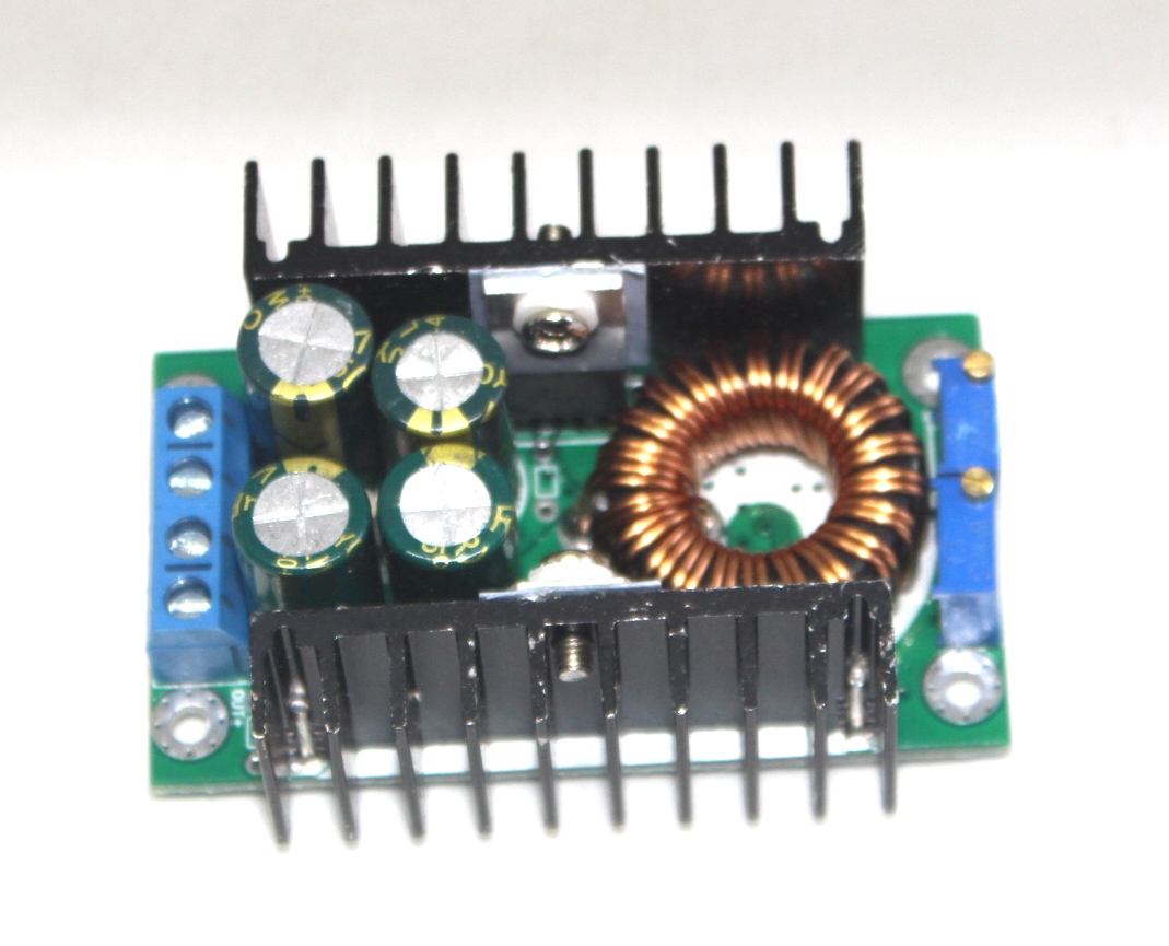
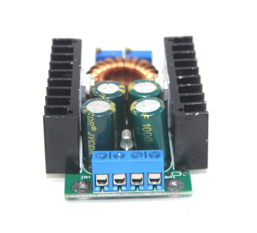
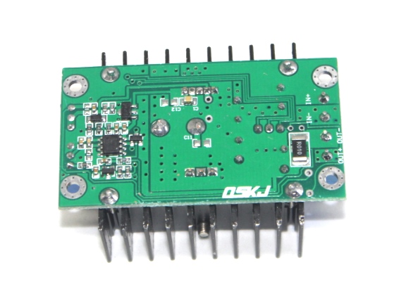
constant current and voltage 8A 300W DC-DC Buck module
₦6,200.00
Description:
The Constant Current and Voltage 8A 300W DC-DC Buck Module is a high-power step-down converter designed for applications requiring efficient voltage regulation and stable current supply. It is ideal for power-hungry devices and systems that require precise voltage and current control, such as battery charging, LED drivers, and power supply systems.
Key Features:
- High power output: Capable of delivering up to 300W.
- Adjustable output: Allows fine-tuning of both voltage and current.
- Wide input voltage range: Suitable for various power sources.
- High efficiency: Ensures minimal energy loss during conversion.
- Protection features: Includes over-temperature, over-current, and short-circuit protection.
- LED indicators: Provide status information for easy monitoring.
Technical Specifications:
- Input Voltage: 10V to 60V DC
- Output Voltage: 1.2V to 36V DC (adjustable)
- Output Current: Up to 8A (adjustable)
- Power Output: Up to 300W
- Efficiency: Up to 95%
Applications:
- Battery charging: Ideal for charging various types of batteries with precise current and voltage control.
- LED drivers: Provides stable power for high-power LED applications.
- Power supply systems: Suitable for use in custom power supply projects.
- Industrial equipment: Powers various industrial devices requiring stable DC power.
- DIY electronics: Perfect for hobbyists and engineers working on high-power projects.
Datasheet:
For detailed technical information and specifications, please refer to the datasheet for the Constant Current and Voltage 8A 300W DC-DC Buck Module.
In stock
Technical Specifications:
· 300W 8A 7-32V to 0.8-28V DC CC CV Buck Step-Down Converter Power Supply Step Down Module Adjustable Voltage Regulator LED Driver
· High-power, constant current LED driver
· Battery charger
· Vehicle-mounted power supply
· Low voltage system power supply
· Non-isolated step-down CC CV Buck module with on-board LED load indicator
· Input voltage: DC 7-32V
· Output Voltage: DC 0.8-28V (Adjustable)
· Output Current: 8A (MAX), more than 60Deg please strengthen heatsink
· Continuous Current Range: 0.2-8A Adjustable
· Output Power: 300W (MAX)
· Conversion efficiency: 95% (more input voltage, more efficiency)
· Output ripple: 50mV
· Working Temperature: industrial (- 40 ° c to +85 °c) (environmental temperature, more than 40 degrees, please reduce power to use, or – enhance cooling)
· No-load current: 20mA (input 24V ,Output 12V for reference)
· Voltage regulation: ± 1%
· Load regulation: ± 1%
· Dynamic response speed: 200uS 5%
· Short circuit protection: YES
· Input Reverse protection: No (please comply with a reverse protection or connect a diode at input parts.)
· Size : 65 x 47 x 22 mm
· On-board LED load indications: red = load present (eg. ‘battery charging’), green = no load (eg. ‘battery charged’ or output disconnected)
Features:
1. Fixed turn lamp current is 0.1 times the current value( Used to identify whether the battery is fully charged When charging).
2. Made from a dedicated benchmark IC and high-precision current sensing resistor, proving a more stable
constant current, (when 20°C to 100°C constant current 1A, temperature drift less than 1%). Particularly suitable for LED driver.
3. High output current, the max output current can reach 8A.
4. Four high frequency capacitance, can lower output ripple, enhance the work stabilization.
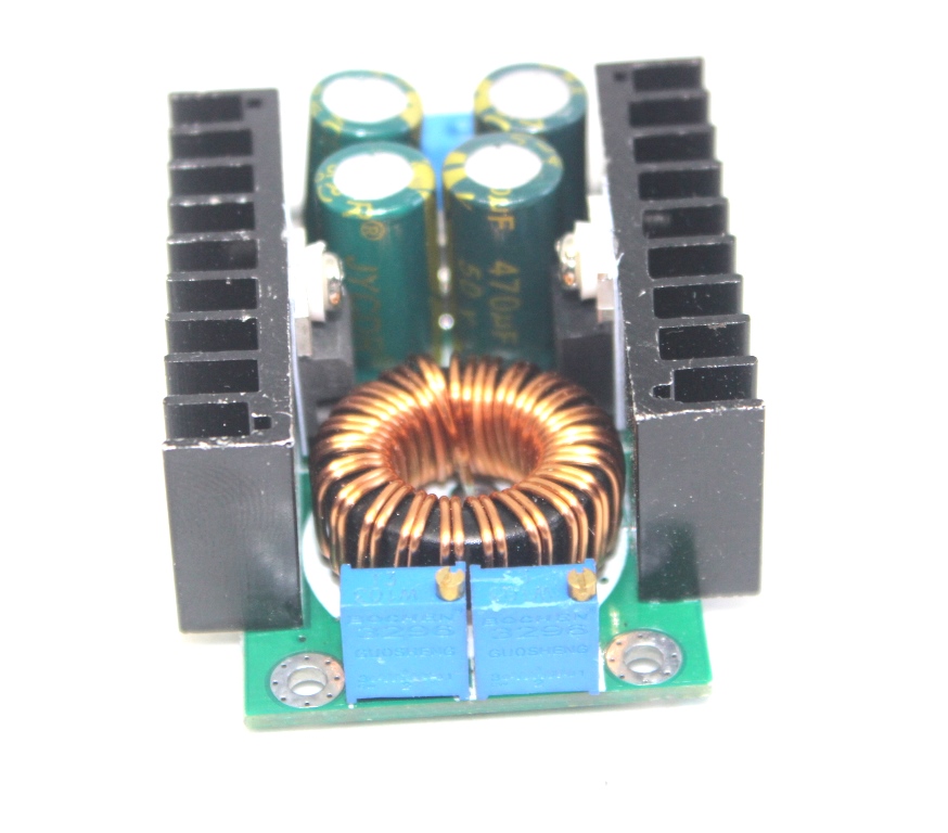
5. Double heat sink design. MOS schottky diode independent heat sink,which heat dissipation is good, and won’t affect each other.
6. Using large size Sendust Core and double pure copper wiring, improve working efficiency, reduce fever.
7. 3296 multiturn potentiometer,high accuracy voltage and current regulation, good stability.
8. Double color lamp, working condition be clear at a glance
9. Voltage and current are adjustable,which effect is good.
Applications:
1. High-power LED driver.
2. Lithium battery(or lead accumulator) charge.
3. Vehicle-mounted power supply.
4. Low voltage system power supply.
5. 6V, 12V, 14V, 24V battery charge.
6. On-board laptop power supply.
7. regulated power supply.
8.Low voltage power supply system.
Module adjustment:
1. When the module output voltage can not be adjusted (the output voltage is always equal to the input voltage) Please adjust the potentiometer counterclockwise 20 laps (20 turns) or more till it works.
2. Turn trimmers CLOCKWISE to INCREASE, ANTICLOCKWISE to DECREASE.
3. When adjust the blue potentiometer ,please use a multimeter to monitor the voltage
4. The trimmer nearest the voltage output adjusts the output CURRENT (CC)
5. The trimmer nearest the voltage input adjusts the output VOLTAGE (CV)
Charger application – intructions:
1. First determine the float voltage and charging current required by the battery to be charged (the ‘target battery’). The target battery disconnected from the module output, apply a voltage of 7V – 32V to the module input, being sure to observe correct polarity.
2. Using the CV trimmer, adjust the output voltage to about 5V.
3. Switch your multimeter into its 10A current scale and measure the module’s short-circuit output current. Turn the CC trimmer to adjust the current to the charging current required by target battery.
4. Using the CV trimmer, adjust the module’s output voltage to the float voltage required by the target battery.
5. Connect the target battery to the module output, observing correct polarity. Charging of the battery should commence
Constant current LED Driver Application – Instructions:
1. First determine the operating current and maximum operating voltage of the LED you need to drive.
2. With the CV trimmer, adjust the output voltage to about 5V.
3. Switch your multimeter into its 10A current scale and Specifications:
· 300W 8A 7-32V to 0.8-28V DC CC CV Buck Step-Down Converter Power Supply Step Down Module Adjustable Voltage Regulator LED Driver
· High-power, constant current LED driver
· Battery charger
· Vehicle-mounted power supply
· Low voltage system power supply
· Non-isolated step-down CC CV Buck module with on-board LED load indicator
· Input voltage: DC 7-32V
· Output Voltage: DC 0.8-28V (Adjustable)
· Output Current: 8A (MAX), more than 60Deg please strengthen heatsink
· Continuous Current Range: 0.2-8A Adjustable
· Output Power: 300W (MAX)
· Conversion efficiency: 95% (more input voltage, more efficiency)
· Output ripple: 50mV
· Working Temperature: industrial (- 40 ° c to +85 °c) (environmental temperature, more than 40 degrees, please reduce power to use, or – enhance cooling)
· No-load current: 20mA (input 24V ,Output 12V for reference)
· Voltage regulation: ± 1%
· Load regulation: ± 1%
· Dynamic response speed: 200uS 5%
· Short circuit protection: YES
· Input Reverse protection: No (please comply with a reverse protection or connect a diode at input parts.)
· Size : 65 x 47 x 22 mm
· On-board LED load indications: red = load present (eg. ‘battery charging’), green = no load (eg. ‘battery charged’ or output disconnected)
Features:
1. Fixed turn lamp current is 0.1 times the current value( Used to identify whether the battery is fully charged When charging).
2. Made from a dedicated benchmark IC and high-precision current sensing resistor, proving a more stable
constant current, (when 20°C to 100°C constant current 1A, temperature drift less than 1%). Particularly suitable for LED driver.
3. High output current, the max output current can reach 8A.
4. Four high frequency capacitance, can lower output ripple, enhance the work stabilization.
5. Double heat sink design. MOS schottky diode independent heat sink,which heat dissipation is good, and won’t affect each other.
6. Using large size Sendust Core and double pure copper wiring, improve working efficiency, reduce fever.
7. 3296 multiturn potentiometer,high accuracy voltage and current regulation, good stability.
8. Double color lamp, working condition be clear at a glance
9. Voltage and current are adjustable,wich effect is good.
Applications:
1. High-power LED driver.
2. Lithium battery(or lead accumulator) charge.
3. Vehicle-mounted power supply.
4. Low voltage system power supply.
5. 6V, 12V, 14V, 24V battery charge.
6. On-board laptop power supply.
7. regulated power supply.
8.Low voltage power supply system.
Module adjustment:
1. When the module output voltage can not be adjusted (the output voltage is always equal to the input voltage) Please adjust the potentiometer counterclockwise 20 laps (20 turns) or more till it works.
2. Turn trimmers CLOCKWISE to INCREASE, ANTICLOCKWISE to DECREASE.
3. When adjust the blue potentiometer ,please use a multimeter to monitor the voltage
4. The trimmer nearest the voltage output adjusts the output CURRENT (CC)
5. The trimmer nearest the voltage input adjusts the output VOLTAGE (CV)
Charger application – intructions:
1. First determine the float voltage and charging current required by the battery to be charged (the ‘target battery’). The target battery disconnected from the module output, apply a voltage of 7V – 32V to the module input, being sure to observe correct polarity.
2. Using the CV trimmer, adjust the output voltage to about 5V.
3. Switch your multimeter into its 10A current scale and measure the module’s short-circuit output current. Turn the CC trimmer to adjust the current to the charging current required by target battery.
4. Using the CV trimmer, adjust the module’s output voltage to the float voltage required by the target battery.
5. Connect the target battery to the module output, observing correct polarity. Charging of the battery should commence
Constant current LED Driver Application – Instructions:
1. First determine the operating current and maximum operating voltage of the LED you need to drive.
2. With the CV trimmer, adjust the output voltage to about 5V.
3. Switch your multimeter into its 10A current scale and measure the module’s short-circuit output current. Turn the CC trimmer to adjust the current to the operating current of your LED.
4. Adjust the CV trimmer to make the output voltage reach the maximum LED operating voltage.
5. Connect LED, test.. Turn the CC trimmer to adjust the current to the operating current of your LED.
4. Adjust the CV trimmer to make the output voltage reach the maximum LED operating voltage.
5. Connect LED, test.

