Subtotal: ₦106,470.00
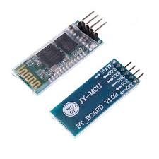
Hey there guys, this is your hardware friend Kayode. Today we will be controlling the arduino input/output pins via Bluetooth. It will be cool to be able to control an appliance remotely from the comfort of your bed, right? I think so too. The Bluetooth module that we will be using is the HC-05 Bluetooth module that comes on a breakout board. So we will connect this module to a smartphone so that we can easily control the arduino via an android app on the smartphone.
HC-05 BLUETOOTH MODULE
The HC-05 is a very popular Bluetooth module. This is due to its flexibility and ease of use. It is flexible because it can be configured as a master or a slave compared to its contemporary the HC-06 which can only be used in slave mode. There are many versions of this board but the one that comes on a breakout board is the best as it allows for easy connection with the arduino and other microcontrollers. The HC-05 is a Bluetooth serial port protocol module. This means that it communicates serially with the arduino. The HC-05 used in this tutorial is 5V tolerant because it comes on a breakout board which has a 3.3V voltage regulator.
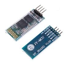
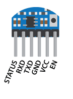
The HC-05 data pins work at logic voltage level of 3.3V. This means that the data pins only support 3.3V and voltage greater than 3.3V will fry the Bluetooth module. The pin-out of the module is shown below.
COMPONENTS NEEDED
For this tutorial, we will need the following components;
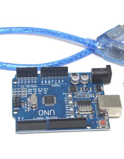
- Arduino uno
- HC-05 Bluetooth module
- LED(4)
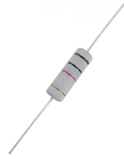
- 220Ω resistor(4)
- 1KΩ resistor(1)
- 1.8KΩ resistor(1)
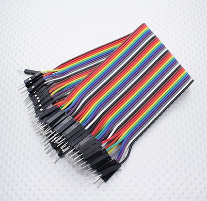
- Jumper wires
- Breadboard
- Your attention (Hope you will give it to me?)
CIRCUIT DIAGRAM
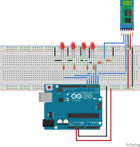
The various components were connected together as shown below.
The Tx (Transmit) pin of the arduino which has 5V output was connected through a voltage divider to the Rx (Receive) pin of the arduino so as not to damage the module. The voltage divider gave an output of about 3.28V which is sufficient for the receive pin HC-05. The LED’s represent our load. You can replace this with any load you like but the load must be connected appropriately.
CODE EXPLANATION
First, we begin by setting up our baud rate for serial communication between the module and the arduino. The default baud rate of the HC-05 is 9600bps. We also initialize the pins which our LED’s will be connected to and then configure the pins as an output. The for loop was used to perform this operation. The for allow for the configuration of several pins with minimal lines of code.
void setup() {
  // put your setup code here, to run once:
// initialize serial communication:
  Serial.begin(9600);

  // initialize the LED pins:
  for (int ledPin = 2; ledPin < 6; ledPin++) {
    pinMode(ledPin, OUTPUT);
  }
}
In the void loop section, the line of code shown below helps to check if serial data is available i.e if a command has been received via Bluetooth. If that is received, the data is read using the Serial.read() function and stored in the int BT command variable.
while (!Serial.available());      //The program remains stuck here till a command is available over seral i.e a command is sent through Bluetooth.
 {
 int BTcommand = Serial.read(); //the command sent through Bluetooth is read and saved
 // in this example, though, you're using single quotes to tell
 // the controller to get the ASCII value for the character.  For
 // example 'A'=65, 'a' = 97, 'b' = 98, and so forth:
Next is the switch case statement which takes in the received data and checks to see if the data corresponds to any of the already set conditions. If the data corresponds, the appropriate action is taken that is to turn a led ON or OFF.
switch (BTcommand) {
      case 'A':
        digitalWrite(2, HIGH);
        break;
      case 'B':
        digitalWrite(3, HIGH);
        break;
      case 'C':
        digitalWrite(4, HIGH);
        break;
      case 'D':
        digitalWrite(5, HIGH);
        break;
      case 'a':
        digitalWrite(2, LOW);
        break;
      case 'b':
        digitalWrite(3, LOW);
        break;
      case 'c':
        digitalWrite(4, LOW);
        break;
      case 'd':
        digitalWrite(5, LOW);
        break;
      default:
        // turn all the LEDs off:
        for (int ledPin = 2; ledPin < 6; ledPin++) {
          digitalWrite(ledPin, LOW);
        }
    }
}
}
FULL CODE
void setup() {
  // put your setup code here, to run once:
// initialize serial communication:
  Serial.begin(9600);

  // initialize the LED pins:
  for (int ledPin = 2; ledPin < 6; ledPin++) {
    pinMode(thisPin, OUTPUT);
  }
}

void loop() {
  // put your main code here, to run repeatedly:
 while (!Serial.available());      //The program remains stuck here till a command is available over seral i.e a command is sent through bluetooth.
 {
 int BTcommand = Serial.read(); //the command sent through Bluetooth is read and saved
 // in this exmaple, though, you're using single quotes to tell
 // the controller to get the ASCII value for the character.  For
 // example 'A'=65, 'a' = 97, 'b' = 98, and so forth:

  switch (BTcommand) {
      case 'A':
        digitalWrite(2, HIGH);
        break;
      case 'B':
        digitalWrite(3, HIGH);
        break;
      case 'C':
        digitalWrite(4, HIGH);
        break;
      case 'D':
        digitalWrite(5, HIGH);
        break;
      case 'a':
        digitalWrite(2, LOW);
        break;
      case 'b':
        digitalWrite(3, LOW);
        break;
      case 'c':
        digitalWrite(4, LOW);
        break;
      case 'd':
        digitalWrite(5, LOW);
        break;
      default:
        // turn all the LEDs off:
  for (int ledPin = 2; ledPin < 6; ledPin++) {
          digitalWrite(thisPin, LOW);
        }
    }
}
}
SMARTPHONE BLUETOOTH SETTINGS
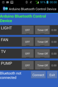
To pair the HC-05 to the smartphone, we use the default password of the HC-05 module which is 1234. After pairing the devices, we need an application for controlling the Arduino. There are so many applications for Bluetooth control on Google Play Store. In this tutorial, we will make use of Arduino Bluetooth control device app. This app is very reliable and can control up to 8 loads. The screenshot of the app is shown below.
When the connect button is pressed, the app brings up a list of available devices and if the HC-05 is properly connected it should be on the list. Click on the HC-05 and connect using the default password 1234. After connection, you are good to go. The app is a very good app as it allows us to time a load for minimum of 1 minute and maximum of 4 hours.
In order to understand how the app works, check out the information below.
Device 1 ON sent ‘A’ Device 1 OFF sent ‘a’
Device 2 ON sent ‘B’ Device 2 OFF sent ‘b’
Device 3 ON sent ‘C’ Device 3 OFF sent ‘c’
Device 4 ON sent ‘D’ Device 4 OFF sent ‘d’
Device 5 ON sent ‘E’ Device 5 OFF sent ‘e’
Device 6 ON sent ‘F’ Device 6 OFF sent ‘f ’
Device 7 ON sent ‘G’ Device 7 OFF sent ‘g’
Device 8 ON sent ‘H’ Device 8 OFF sent ‘h’
When the button for the first device is pressed, the app sends ‘A’. The data sent will now be available in the Tx pin of the Bluetooth module which is connected to the Rx pin of the arduino. Since the arduino continuously check for serial data, it receives it and stores it the BTcommand variable and then switches on the device. If that same button is pressed again, the app sends small letter ‘a’ to the Bluetooth module and then the arduino receives it and turns off the corresponding device.
There is also a button to turn on the timer for each device. The app will automatically send an OFF command to the system when the time set elapse.
To enjoy this nice android app, you can download the app here.
That will be all for this tutorial. Feel free to ask question and I will be glad to answer. Till next time keeping creating.
Yours geekly,
Kayode.



Haaa bro kay thanks so much