- You have no items in your shopping cart
- Subtotal: ₦0.00
Hey there guys, it’s your hardware friend kayode and together today we will be focusing on the TSOP1738 IR receiver. The TSOP1738 belongs to the TSOP17xx family. The xx represents the modulating frequency which in the case of the TSOP1738 is 38Khz. IR Transmitter and receiver is used to control any device wirelessly. We make use of them daily in our various homes. Television remote and Television are the best example of IR transmitter and receiver we can find around. TV generally consist TSOP1738 as the IR receiver, which senses modulated IR pulses and convert them into electrical signal.

Features
- Photo Detector, IR Filter, Preamplifier and PCM frequency filter in one package
- CMOS and TTL Compatible
- Active Low Output
- Immunity against ambient light
- Low Power Consumption
- Able to transfer data continuously up to 2400bps
- Supply Voltage : 4.5 – 5.5V
- Internal filter for PCM frequency
Working principle of the TSOP1738
When the IR remote is pressed it sends out IR radiation. The TSOP1738 detects the IR which is switching on and off at the rate of 38Khz. TSOP’s output is active low, means its output will continue to remain HIGH when there is no IR, and becomes low when it detects IR radiation. So as to eliminate interference, the TSOP1738 operates at a particular frequency so that other IRs in the environment can’t interfere, except the modulated IR of particular frequency.
Components
We will need the following components in order to work with the TSOP1738
- Arduino uno
- Breadboard
- TSOP1738
- IR remote
- LED(2)
- Resistor (220R)
- Jumpers
Circuit diagram
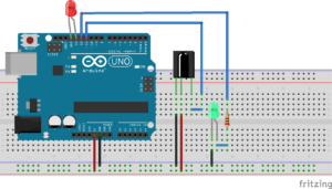
Connect the above mentioned components as shown in the schematics below
The TSOP1738 has three pins from left to right as shown above are Gnd, Vcc and output. The Gnd pin of the TSOP1738 is connected to the ground of the arduino, the Vcc is connected to the 5v supply of the arduino and the output pin is connected to digital pin 11 of the arduino. The anode of the LED is connected to digital pin 13 while the cathode is connected to ground. The led that serves as our load is connected to digital pin 12 via 220R resistor.
NOTE: No current limiting resistor is used for the LED since pin 13 already has an in-built resistor. If any other pin is used, a current limiting resistor must be used.
Decoding IR Remote Control Signals using Arduino
When any button of the IR Remote is pressed, the remote sends a code in form of train of encoded pulses using 38Khz modulating frequency. These pulses are received by TSOP1738 sensor and read by Arduino and then Arduino decodes received train of pulse into a hex value and in turn will display it on the serial monitor.
Before we step into the code we have to do the following
- Download the IR remote library from here
- Unzip it, and place it in your Arduino ‘Libraries’ folder.
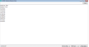
Run the below program from your Arduino and open the Serial Monitor window in Arduino IDE. Now press any IR Remote button and see the corresponding decoded hex output in Serial Monitor window. You should see something like the screenshot shown below if you did everything correctly.
Code Explanation
We will do a little breakdown of the code and i will leave you with the code at the end. First, we are going include the IR remote library and also declare the pins we will be connecting things to.
#include <IRremote.h>

int RECV_PIN = 11;

#define LED_PIN 12


IRrecv irrecv(RECV_PIN);

decode_results results;
Next, we will setup serial communication and also display some information on the serial monitor for debugging purposes and also to enable the led to blink during reception since we can’t see infrared blinking the led can help us to troubleshoot. We also set the led as output and make its initial state low.
void setup()
{
  Serial.begin(9600);
  // In case the interrupt driver crashes on setup, give a clue
  // to the user what's going on.
  Serial.println("Enabling IRin");
  irrecv.enableIRIn(); // Start the receiver
   irrecv.blink13(true);
  Serial.println("Enabled IRin");
  pinMode(LED_PIN,OUTPUT);
  digitalWrite(LED_PIN,LOW);
}
Finally, in our void loop() section, data is received from the TSOP1738 and it is converted into hexadecimals and printed on the serial monitor. When the appropriate button is pressed on the remote the led comes on else it goes off.
void loop() {
  if (irrecv.decode(&results)) {
    Serial.println(results.value,HEX);
    if(results.value==0xE8289565)  // change this to the hex value of your own desired button
    {
     digitalWrite(LED_PIN,HIGH);
    }
    else
  {
     digitalWrite(LED_PIN,LOW);
  }
  irrecv.resume(); // Receive the next value
  delay(100);
  }
}
CODE
#include <IRremote.h>

int RECV_PIN = 11;
#define LED_PIN 12
IRrecv irrecv(RECV_PIN);

decode_results results;

void setup()
{
  Serial.begin(9600);
  // In case the interrupt driver crashes on setup, give a clue
  // to the user what's going on.
  Serial.println("Enabling IRin");
  irrecv.enableIRIn(); // Start the receiver
  irrecv.blink13(true);
  Serial.println("Enabled IRin");
  pinMode(LED_PIN,OUTPUT);
  digitalWrite(LED_PIN,LOW);
}

void loop() {
  if (irrecv.decode(&results)) {
    Serial.println(results.value,HEX);
    if(results.value==0xE8289565)
    {
     digitalWrite(LED_PIN,HIGH);
    }
    else
  {
     digitalWrite(LED_PIN,LOW);
  }
  irrecv.resume(); // Receive the next value
  delay(100);
  }
}
So that will be all guys contact me if you have any question. Till next time, Keep creating and hacking.
Yours geekly,
Kayode.


