Subtotal: ₦158,650.00

hi guys, today we will focus on doing something a lot of people have found difficult to do with the raspberry pi 3; Connecting components that use the UART communication mode, to the raspberry pi 3.
The SoCs used on the Raspberry Pis have two built-in UARTs, a PL011 and a mini UART. They are implemented using different hardware blocks, so they have slightly different characteristics and capabilities. From the Raspberry pi 3 and pi zero(the class of Raspberry Pi with Wireless/Bluetooth Module), the PL011 UART is connected to the BT module, while the mini UART is used for Linux console output.
In Linux device terms, by default, /dev/ttyS0 refers to the mini UART, and /dev/ttyAMA0 refers to the PL011. The primary UART is that assigned to the Linux console, which depends on the Raspberry Pi model as described above, and can be accessed via /dev/serial0.
On all other models of the raspberry pi, except Pi3 and Zero, the PL011 is used for the Linux console output this causes a bit of problem when trying to implement UART communication for the raspberry pi3 as there are issues with the mini UART which is really of mini capabilities.
This Tutorial will show you how to disable the the bluetooth on the PL011 UART and enable the Pi for communication with UART based components like GSM modules, GPS modules(which is the focus of this tutorial) among others.
Required Components
Some of the components needed to follow this tutorial all of which can be bought from our website by clicking on them are listed below,
3. Breadboard
4. Jumper wire
5. 8g Sd card running raspbian jessie
Setting Up the Raspberry pi
To be able to achieve communication with the raspberry pi 3 via UART using the PL011 we need to do a 1 time setup of the Pi. follow the steps below one after the other and you will be fine.
I want to assume you are already familiar with the Pi or at least know how to setup the raspbian OS on your pi and ssh into the pi using putty. Clement Dike wrote a wonderful tutorial on that here.
Step 1
The first thing I like to do before starting any raspberry pi project is updating the pi which is done using;
sudo apt-get update
sudo apt-get upgrade
when this is done, reboot your raspberry pi to save changes using;
sudo reboot
wait for some few minutes for the pi to come back on, then restart the session.
Step 2
under this step we will enable the PL011 UART.
The first thing we need to do is to edit the raspberry pi’s config.txt file
to do this, we use ;
sudo nano /boot/config.txt
to open the config file for editing.
we then add the following lines at the bottom of the config.txt file
dtparam=spi=on
dtoverlay=pi3-disable-bt
core_freq=250
enable_uart=1
force_turbo=1
The nature of this blog post is a little bit advanced so i will try and explain what those lines do.
force_turbo enables UART to use the maximum core frequency which we are setting in this case to be 250. The reason for this is to ensure consistency and integrity of the serial data been received.
The dtoverlay=pi3-disable-bt disconnects the bluetooth from the ttyAMA0 this is to allow us access to use the full UART power available via ttyAMAO instead of the mini UART ttyS0.
enable_uart = 1 means exactly what you think it does, turns on the UART.
After entering those commands at the bottom of the config file, save the file and exit using CTRL X followed by y.
The second thing we need to do is to edit the cmdline.txt file of the raspberry pi to remove the mini UART from it.
sudo nano /boot.cmdline.txt
replace the text in the file with the lines below or edit to remain;
dwc_otg.lpm_enable=0 console=tty1 root=/dev/mmcblk0p2 rootfstype=ext4 elevator=deadline fsck.repair=yes rootwait quiet splash plymouth.ignore-serial-consoles
save and exit.
will this done, we need to reboot the Pi to effect changes.
The next thing we need to do with the pi back on is to disable the serial getty service of the mini UART.
sudo systemctl stop serial-getty@ttyS0.service
sudo systemctl disable serial-getty@ttyS0.service
This can be enabled later should you ever need it using
sudo systemctl enable serial-getty@ttyS0.service
sudo systemctl start serial-getty@ttyS0.service
with the serial getty service disabled, we then perform a reboot to effect changes.
With the Pi back on, we are finally ready to activate the ttyAMA0 i.e the PL011 UART. This is done using;
sudo systemctl enable serial-getty@ttyAMA0.service
Step 2: Connecting the GPS Module
At this stage our pi is fully ready to communicate with any component or device via UART be it a GSM module or any other components. As described in the beginning we will be hooking up a GPS module to the Pi.
For this tutorial, we will basically be displaying the GPS coordinates on the Pi’s terminal. I will do a follow up tutorial to show you how you can send the send the GPS coordinates via Email and build yourself a valuable tracking device.
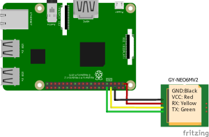
Schematics
Connect your raspberry pi to the GPS module as shown in the image below.
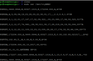
with the connection done, you can test if the UART setup we did worked using;
1 |
sudo cat /dev/ttyAMA0 |
you should get something like the image shown below.
you can go over the steps again if you have any issues or drop me a comment.
Code
With schematics done, we will write a python script to collect the nmea data from the gps module via serial and print the longitude and latitude on the terminal.
To be able to parse the NMEA data easily, we will be using the Pynmea2 python library, and it can be installed by running;
Cd ~
pip install pynmea2
of course an enter after the first line, then enter the second.
With Pynmea2 installed we can move to the code proper. I will do a breakdown to ensure we all follow with the full code at the end.
The first thing we do in the code is import the needed library and that is done using the lines of code below.
import time
import serial
import string
import pynmea2
Next thing to be done is indicate the port to which the GPS is connected.
port = "/dev/ttyAMA0"
Next we create the serial object similar to Arduino’s Serial.begin()
ser = serial.Serial(port, baudrate = 9600, timeout = 0.5)
Next we read data using the line below.
data = ser.readline()
The next line of code involves parsing the data using the pynmea2 library and storing the passed data in the variable name msg. Querrying msg.lat will give us the latitude of the location while msg.lon
if data[0:6] == '$GPGGA':
        msg = pynmea2.parse(data)
        latval = msg.lat
with this done, we then convert to string and print on the terminal.
 concatlat = "lat: " + str(latval)
        print concatlat
open a nano editor
sudo nano gpscode.py
copy/type the full code into the editor then press CTRL + X followed by y to save and exit.
Finally, here is the full code.
import time
import serial
import string
import pynmea2

port = "/dev/ttyAMA0"

ser = serial.Serial(port, baudrate = 9600, timeout = 0.5)

while 1:
    try:
        data = ser.readline()
    except:
        print("loading")
    if data[0:6] == '$GPGGA':
        msg = pynmea2.parse(data)
        latval = msg.lat
        concatlat = "lat: " + str(latval)
        print concatlat
        longval = msg.lon
        concatlon = "Long: " + str(longval)
        print concatlon

    time.sleep(1)
Then use;
sudo python gpscode.py
to run the script, if your gps has got a fix, you should see the data streaming in.
That’s it guys. I know the post is a little bit technical, the joy of being a maker is when you crack “nuts” like this. Feel free to reach out to me via comments if you have any questions.
cheers.


Hi, Mr. Odunlade just want to say I appreciate your effort. Please keep the tutorials going. Is it possible to have interested one like me also write up some tutorials for posting?
Hey, I liked your tutorial. It was really descriptive. I’m working on a project where I need my bluetooth on my pi to be active as I got 2 devices connected over it. Is there a way to use this GPS without disabling bluetooth?? Your input will be really appreciated.
Thanks