|
Description |
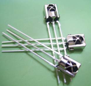
The TSOP 1838 is a compact IR (Infrared) receiver module designed for use in remote control systems. It can detect modulated IR signals at 38 kHz, making it ideal for applications such as remote control reception, IR data transmission, and IR-based communication systems. The TSOP 1838 provides high sensitivity and reliable performance in a small package.
Key Features:
- Pin diode and preamplifier in one package
- Modulated IR signal detection at 38 kHz
- High sensitivity and excellent noise immunity
- Low power consumption
- TTL and CMOS compatible output
- Internal filter for PCM frequency
- Improved shielding against electrical field disturbance
- Suitable for continuous and burst data transmission
Technical Specifications:
- Carrier Frequency: 38 kHz
- Supply Voltage: 2.7V to 5.5V
- Supply Current: 0.4 mA (typical)
- Peak Wavelength: 940 nm
- Reception Range: Up to 45 meters (with proper IR transmitter)
- Viewing Angle: ±45 degrees
- High-Level Output Voltage: ≥ Vcc – 0.2V
- Low-Level Output Voltage: ≤ 0.2V
- Output Pulse Width: Typically 400 µs
- Operating Temperature Range: -25°C to +85°C
- Package Type: 3-pin epoxy package
Applications:
- IR remote control systems
- Consumer electronics (TVs, VCRs, DVDs, audio equipment)
- Home automation
- IR data communication
- Infrared object detection
- Robotics
Usage:
- Connection:
- Connect the Vcc pin to a power supply (2.7V to 5.5V).
- Connect the GND pin to ground.
- Connect the OUT pin to the input of a microcontroller or other logic-level input device.
- Operation:
- When an IR signal at 38 kHz is received, the OUT pin goes low.
- When no IR signal is received, the OUT pin stays high.
- Use the output signal to control devices or process the data using a microcontroller.
- Interfacing:
- Interface the TSOP 1838 with a microcontroller to decode the received IR signals.
- Implement software to process the decoded IR signals for controlling various devices.
Caution:
- Ensure the IR receiver is not exposed to direct sunlight or strong ambient light sources, as this may affect its performance.
- Handle the module with care to avoid damage from electrostatic discharge (ESD).
Datasheet:
For detailed technical specifications, refer to the TSOP 1838 Datasheet.
|
The ACS712 is a current sensor from Allegro Microsystems designed to measure current with a maximum rating of 30A. It provides an analog output voltage that is proportional to the current flowing through the sensor. The ACS712 is widely used in power monitoring, load current measurement, and over-current protection applications due to its high accuracy and ease of integration with microcontrollers and other electronic systems.
Key Features:
- Measures AC and DC current up to 30A
- Provides an analog output voltage proportional to the current
- High accuracy with low offset and temperature drift
- Integrated Hall effect sensor for non-invasive current measurement
- Small size and easy to integrate into various circuits
- On-chip signal conditioning and protection
Technical Specifications:
- Sensor Type: Hall Effect Current Sensor
- Current Range: ±30A (AC or DC)
- Output Voltage Range: Typically 0V to Vcc
- Sensitivity: 66mV/A (typical)
- Operating Voltage: 5V ±5%
- Zero Current Offset Voltage: Vcc/2 (typical)
- Temperature Range: -40°C to +85°C
- Current Measurement Accuracy: ±1.5% of full-scale current (typical)
- Package Type: SOP-8 or similar
Applications:
- Power monitoring and control
- Over-current protection systems
- Load current measurement in power supplies
- Motor current sensing
- Energy monitoring and management
Usage:
- Connect the ACS712 sensor to your microcontroller or development board, ensuring correct connection of the power supply (Vcc, GND) and the output voltage pin.
- Route the current-carrying conductor through the sensor to measure the current.
- Read the analog output voltage, which is proportional to the current, and process it according to your application needs.
- Calibrate the sensor if necessary to ensure accurate current measurement.
Caution:
- Ensure the current flowing through the sensor does not exceed the maximum rating (30A) to avoid damage.
- Properly insulate and protect the sensor and connections to prevent short circuits and ensure safe operation.
- Verify the power supply voltage and connections to avoid incorrect readings or sensor damage.
Datasheet:
For detailed technical specifications, refer to the ACS712 Datasheet.
|
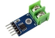
The MAX6675 thermocouple module is a sophisticated temperature-sensing device that interfaces with a K-type thermocouple to provide accurate temperature readings. It converts the thermocouple’s analog signals to digital data, which can be easily read by a microcontroller through an SPI interface. This module is ideal for applications requiring precise temperature measurements and is commonly used in industrial, laboratory, and home automation projects.
Key Features:
- Thermocouple Compatibility: K-type
- Temperature Range: 0°C to 1024°C
- Resolution: 0.25°C
- Interface: SPI (Serial Peripheral Interface)
- Accuracy: ±2°C for temperatures ranging from 0°C to 700°C
- Integrated Cold-Junction Compensation: Ensures accurate temperature readings by compensating for the temperature at the thermocouple’s reference junction
Technical Specifications:
- Operating Voltage: 3.0V to 5.5V
- Temperature Range: 0°C to 1024°C
- Resolution: 12-bit (0.25°C resolution)
- Accuracy: ±2°C (0°C to 700°C)
- Cold-Junction Compensation: Integrated
- SPI Clock Frequency: Up to 4.3 MHz
- Package: 8-pin SOIC (MAX6675 chip), module size typically 20 mm x 15 mm
Applications:
- Industrial: Temperature monitoring in furnaces, kilns, and other high-temperature environments.
- Laboratory: Precise temperature measurement in scientific experiments and research.
- Home Automation: Used in heating systems, ovens, and other appliances that require temperature regulation.
- Electronics Projects: Ideal for DIY electronics projects that need temperature sensing capabilities.
- Automotive: Temperature sensing in engines and other automotive components.
Datasheet:
For detailed technical information, refer to the MAX6675 Thermocouple-to-Digital Converter Datasheet provided by the manufacturer.
|
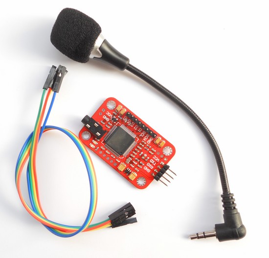
The Voice Recognition Module V3 is a compact and easy-to-use voice recognition module designed for embedded systems. It can be trained to recognize voice commands and respond accordingly, making it ideal for applications in home automation, robotics, and interactive projects. The module supports up to 80 voice commands, with 7 commands being recognized at any given time.
Key Features:
- Supports up to 80 voice commands
- Recognizes 7 voice commands simultaneously
- Speaker-independent and speaker-dependent modes
- Easy UART interface for communication with microcontrollers
- Onboard microphone for voice input
- Low power consumption
- Supports multiple languages
- High accuracy and fast response time
Technical Specifications:
- Supply Voltage: 4.5V to 5.5V
- Current Consumption: 50 mA (max)
- Interface: UART (9600 bps default)
- Recognition Accuracy: 99%
- Recognition Time: < 1 second
- Number of Commands: 80 (in groups of 7)
- Operating Temperature Range: -40°C to +85°C
- Dimensions: 30mm x 20mm x 5mm
Applications:
- Home automation systems
- Voice-controlled robots
- Interactive toys and games
- Voice-activated devices
- Security systems
- Assistive technologies for the disabled
Usage:
- Connection:
- Connect the VCC pin to a 5V power supply.
- Connect the GND pin to ground.
- Connect the RX pin to the TX pin of the microcontroller.
- Connect the TX pin to the RX pin of the microcontroller.
- Training:
- Use the provided software or serial commands to train the module with voice commands.
- Train the module in a quiet environment for best results.
- Store the voice commands in one of the available groups.
- Operation:
- After training, the module can recognize voice commands and send corresponding signals to the microcontroller.
- Use the recognized commands to control devices, trigger actions, or execute programs.
- Programming:
- Write a program on the microcontroller to interface with the module and handle recognized commands.
- Use the UART interface to send and receive data from the module.
Caution:
- Avoid exposing the module to high levels of noise during operation.
- Handle the module carefully to avoid damage from electrostatic discharge (ESD).
- Ensure proper power supply and connections to prevent malfunction.
Datasheet:
For detailed technical specifications, refer to the Voice Recognition Module V3 Datasheet.
|
A tilt sensor is a device used to detect the orientation or inclination of an object. It is typically used in various applications where it is necessary to detect changes in position or to determine if an object has tilted beyond a certain angle. Tilt sensors are widely used in robotics, automotive systems, security systems, and electronic devices for motion detection and orientation sensing.
Key Features:
- Detects changes in orientation or tilt
- Simple and reliable design
- Provides digital output signal
- Low power consumption
- Compact and easy to integrate
- Suitable for a wide range of applications
Technical Specifications:
- Type: Tilt Sensor
- Operating Voltage: Typically 3.3V to 5V (varies by model)
- Output Type: Digital (HIGH/LOW)
- Tilt Angle Range: Typically 15° to 45° (varies by model)
- Current Consumption: Typically less than 1mA
- Dimensions: Varies by product (commonly around 10mm x 5mm x 5mm)
- Operating Temperature Range: -40°C to +85°C
Applications:
- Robotics and automation
- Automotive safety systems
- Security and alarm systems
- Consumer electronics
- Motion detection and orientation sensing
- Industrial equipment
Usage:
- Connect the tilt sensor to your microcontroller or development board, ensuring proper connection of the power supply (VCC, GND) and the output pin.
- Use the digital output signal to detect tilt: the sensor typically outputs a HIGH signal when in the default position and a LOW signal when tilted beyond the specified angle.
- Implement code to monitor the sensor output and trigger appropriate actions or alarms when a tilt is detected.
- Mount the sensor on the object or surface where tilt detection is required, ensuring it is securely positioned.
Caution:
- Ensure proper orientation and mounting of the sensor for accurate tilt detection.
- Avoid exposing the sensor to excessive vibrations or shocks, which may affect its performance.
- Handle the sensor carefully to avoid damage to the internal components.
Datasheet:
For detailed technical specifications, refer to the specific product datasheet provided by the manufacturer.
|
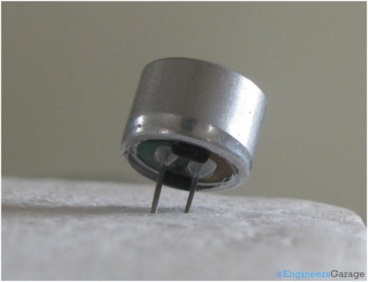
The Condenser Mic 4.5×2.2mm is a small-sized, high-sensitivity electret microphone. It is designed for a wide range of audio applications, including voice recording, telecommunication devices, and various consumer electronics. Its compact size and high sensitivity make it ideal for embedding in small devices.
Key Features:
- High sensitivity and low noise
- Small and compact size
- Wide frequency response
- Low power consumption
- Omnidirectional pickup pattern
- Easy to integrate into electronic circuits
Technical Specifications:
- Type: Electret condenser microphone
- Dimensions: 4.5mm (diameter) x 2.2mm (height)
- Sensitivity: -42dB ±3dB (0dB = 1V/Pa at 1kHz)
- Frequency Response: 20Hz to 16kHz
- Impedance: ≤ 2.2kΩ
- Operating Voltage: 1.5V to 10V DC
- Current Consumption: ≤ 0.5mA
- Signal-to-Noise Ratio: ≥ 60dB
- Directivity: Omnidirectional
- Operating Temperature Range: -20°C to +70°C
Applications:
- Voice recording devices
- Telecommunication equipment
- Hearing aids
- Portable audio recorders
- Consumer electronics
- Smart home devices
- Speech recognition systems
Usage:
- Connection:
- Connect the microphone’s output pin to the input of an amplifier or preamp circuit.
- Connect the power supply (1.5V to 10V DC) to the microphone.
- Ensure the ground connection is properly made to avoid noise interference.
- Integration:
- Place the microphone in a suitable location to capture sound effectively.
- Embed the microphone in devices ensuring the sound entry is not obstructed.
- Circuit Design:
- Use appropriate capacitors and resistors as per the microphone’s requirements.
- Design the circuit to provide a stable power supply and proper impedance matching.
Caution:
- Handle the microphone with care to avoid physical damage.
- Protect the microphone from exposure to moisture and extreme temperatures.
- Avoid applying excessive voltage to prevent damage to the microphone.
Datasheet:
For detailed technical specifications, refer to the Condenser Microphone Datasheet.
|
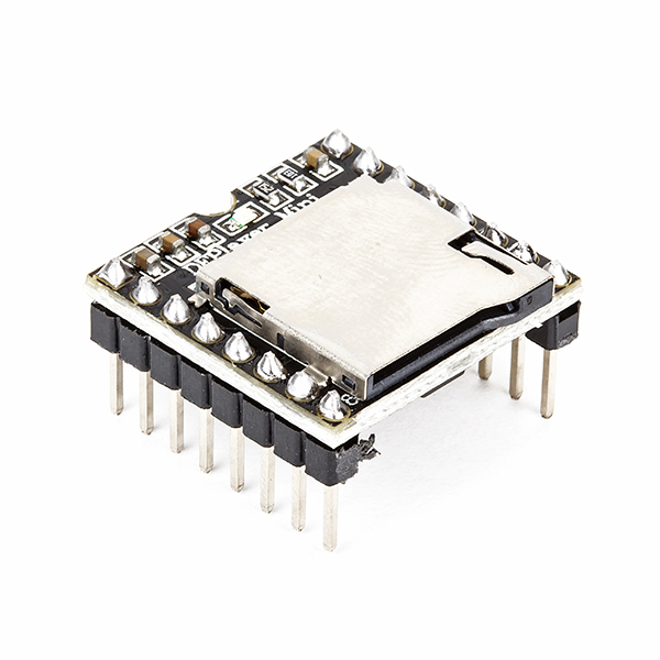
The DF Mini MP3 Player is a compact and cost-effective MP3 module that can be directly connected to a speaker. It can be used as a standalone module with battery, speaker, and push buttons, or in combination with an Arduino or other controller with RX/TX capabilities. It is widely used in applications like voice announcements, sound effects, and audio playback in various projects.
Key Features:
- Compact Size: Small form factor for easy integration
- Storage: Supports microSD cards up to 32GB
- File Format: MP3, WAV, and WMA file formats
- Built-in Amplifier: 3W amplifier for direct speaker connection
- Control Interface: Serial (UART), AD (Analog), or GPIO (General Purpose Input/Output)
- Power Supply: 3.2V to 5.0V DC
Technical Specifications:
- Operating Voltage: 3.2V to 5.0V DC
- Storage Medium: MicroSD card (up to 32GB)
- Audio Formats: MP3, WAV, WMA
- Amplifier: 3W built-in amplifier
- Control Interface:
- Serial (UART): For communication with microcontrollers
- AD (Analog): For controlling playback with potentiometers
- GPIO: For simple control using buttons or switches
- Output: Speaker (direct connection), headphone jack (if available)
- Dimensions: Compact and suitable for integration into various projects
Applications:
- Voice Announcements: Ideal for applications requiring voice prompts or messages.
- Sound Effects: Used in interactive displays, exhibits, and installations.
- Audio Playback: Suitable for DIY projects, toys, and educational tools.
- Embedded Systems: Integrated into products requiring audio feedback or instructions.
- Prototyping: Useful in developing and testing audio-based applications.
Datasheet:
For detailed technical information, refer to the DF Mini MP3 Player datasheet.
|
