|
Description |
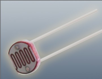
The Photoresistor LDR (Light Dependent Resistor) is a variable resistor whose resistance changes with the light intensity that falls upon it. It is widely used in light sensing applications and projects where detecting light levels is essential. LDRs are cost-effective, easy to use, and suitable for various electronic projects, including light meters, street lights, and other light-sensitive devices.
Key Features:
- Light Sensitivity: Resistance decreases with increasing light intensity
- Simple Interface: Easy to integrate with microcontrollers and analog circuits
- Low Cost: Economical solution for light detection
- Wide Range of Light Detection: Can detect various light levels from low to high intensity
- Compact Size: Fits easily into small projects
Technical Specifications:
- Resistance in Darkness: Typically 1MΩ (depending on specific model)
- Resistance in Bright Light: Typically 10-20kΩ (depending on specific model)
- Spectral Peak: Approximately 540nm (most sensitive to green light)
- Response Time: Rise time ~20ms, fall time ~30ms
- Operating Temperature Range: -30°C to +70°C
- Diameter: Typically 5mm to 10mm (depending on specific model)
Applications:
- Light Meters: Measure light intensity for photography and scientific applications.
- Street Lights: Automatic on/off control based on ambient light levels.
- Alarm Systems: Detect changes in light levels for security purposes.
- Consumer Electronics: Light-sensitive control in devices like clocks and displays.
- Educational Projects: Common component in learning modules for electronics.
Usage:
- Circuit Integration: Connect the LDR in a voltage divider circuit with a fixed resistor to create a variable voltage output based on light intensity.
- Microcontroller Interface: Read the voltage output from the LDR circuit using an analog input pin on a microcontroller.
- Programming: Write code to interpret the analog signal and perform actions based on light levels (e.g., turning on an LED when it gets dark).
- Testing: Calibrate the LDR circuit for the desired light sensitivity by adjusting the fixed resistor value.
Caution:
- Environment: Avoid exposure to extreme temperatures and humidity, which may affect the LDR’s performance.
- Handling: Handle with care to avoid damaging the sensitive surface of the LDR.
Datasheet:
For detailed technical specifications, refer to the Photoresistor LDR Datasheet.
|
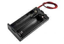
The 2 AA Battery Casing is a compact and convenient holder designed to securely house two AA batteries. This battery casing is ideal for providing a portable power source for various electronic projects, toys, remote controls, and other battery-powered devices. It features durable construction and easy-to-use connectors, ensuring reliable and consistent power delivery to your devices.
Key Features:
- Secure Housing: Holds two AA batteries securely in place
- Durable Construction: Made from high-quality plastic for long-lasting use
- Easy Installation: Snap-fit design for quick and easy battery replacement
- Wire Leads: Pre-attached wire leads for easy connection to your device
- Portable Power Source: Ideal for various DIY electronics and hobby projects
Technical Specifications:
- Battery Type: AA (1.5V each)
- Number of Batteries: 2
- Output Voltage: 3V (when using two 1.5V AA batteries)
- Material: High-quality plastic
- Wire Leads: Typically 150mm in length, pre-tinned for easy soldering
- Dimensions: Approximately 58mm x 33mm x 15mm (L x W x H)
- Weight: Lightweight design for portability
Applications:
- DIY electronics projects
- Battery-powered toys
- Remote controls
- Flashlights
- Educational kits and prototypes
- Portable power supplies
Usage:
- Insert two AA batteries into the casing, ensuring correct polarity.
- Connect the wire leads to your device’s power input, observing correct polarity.
- Secure the casing in place within your project or device.
- Replace batteries as needed to maintain power supply.
Caution:
- Ensure correct battery polarity to avoid damage to the casing or connected device.
- Use high-quality batteries for optimal performance.
- Do not mix old and new batteries or different types of batteries.
- Protect the casing from water and extreme temperatures to ensure longevity.
Datasheet:
For detailed technical specifications, refer to the 2 AA Battery Casing Datasheet.
|
|
The LMV321IDBVR is a low power operational amplifier designed for general-purpose applications where low voltage, low power consumption, and small package size are critical.
Key Features:
- Supply Voltage: Typically operates from 2.7V to 5.5V.
- Low Quiescent Current: Helps in conserving power, suitable for battery-operated devices.
- Low Offset Voltage: Provides accurate amplification of small signals.
- Single Supply Operation: Suitable for applications with single power supply voltage.
- Rail-to-Rail Output: Capable of driving signals close to both supply rails.
- Small Package: Available in SOT-23-5 package, suitable for space-constrained applications.
Technical Specifications:
- Number of Channels: Single operational amplifier.
- Bandwidth: Typically ranges up to several MHz.
- Slew Rate: Provides fast response to input signals.
- Input Offset Voltage: Low input offset voltage for precision applications.
- Temperature Range: Typically operates from -40°C to +125°C.
- Applications: Ideal for battery-powered devices, sensor interfaces, signal conditioning, and portable electronics.
Datasheet:
For detailed technical information, refer to the LMV321IDBVR Datasheet.
|
|
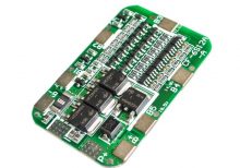
The 6s 15A LiPo Battery BMS is a Battery Management System designed for 6-cell Lithium Polymer (LiPo) batteries. It ensures safe operation by managing the charging and discharging processes, balancing cell voltages, and protecting the battery from overcharge, over-discharge, and short circuits. This BMS is ideal for use in high-performance applications such as drones, RC vehicles, and other battery-powered electronics.
Key Features:
- Designed for 6-cell LiPo batteries (6s configuration)
- Continuous discharge current: 15A
- Balancing function to equalize cell voltages
- Overcharge protection: Disables charging if any cell exceeds the set voltage threshold
- Over-discharge protection: Prevents discharging if any cell drops below the minimum voltage threshold
- Short circuit protection: Disconnects the battery to prevent damage
- Thermal protection: Monitors temperature and protects against overheating
- Low standby current consumption
Technical Specifications:
- Cell Configuration: 6s (6-cell in series)
- Discharge Current: 15A continuous
- Balancing Current: 100mA per cell
- Overcharge Voltage Protection: 4.35V ± 0.05V per cell
- Over-discharge Voltage Protection: 3.0V ± 0.05V per cell
- Short Circuit Protection: Automatic disconnect
- Thermal Protection: Automatic shutdown at high temperatures
- Operating Temperature Range: -20°C to +60°C
- Dimensions: Varies by manufacturer (common sizes: 50mm x 30mm x 5mm)
- Weight: Varies by manufacturer
Applications:
- RC vehicles (drones, cars, boats)
- High-performance electronics
- Electric bikes and scooters
- Battery-powered tools
- Portable devices
Usage:
- Connect the BMS to the LiPo battery’s balance leads and power terminals.
- Ensure proper connections to avoid incorrect wiring.
- Configure the BMS settings if applicable.
- Integrate the BMS with your electronic system and monitor for proper operation.
Caution:
- Properly insulate and handle the BMS to prevent short circuits and physical damage.
- Follow the manufacturer’s guidelines for installation and usage.
- Avoid exposing the BMS to temperatures outside the specified operating range.
Datasheet:
For detailed technical specifications, refer to the datasheet of 6s 15A LiPo Battery BMS.
|
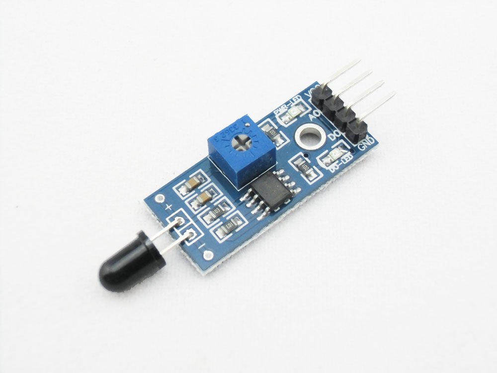
A flame sensor is an infrared (IR) detector used to detect the presence of flame or fire. It is typically used in fire detection and safety systems to provide early warning and activate safety measures. The sensor is sensitive to IR light emitted by flames and can be used in various applications, including security systems, fire-fighting robots, and automatic fire alarm systems.
Key Features:
- Detects infrared light emitted by flames
- High sensitivity and fast response time
- Analog and digital output signals
- Adjustable sensitivity via potentiometer
- Compact and easy to integrate into various systems
- Onboard indicator LED for detection status
Technical Specifications:
- Detection Range: Up to 100cm (varies by model and flame size)
- Wavelength Range: 760nm to 1100nm (IR spectrum)
- Operating Voltage: 3.3V to 5V
- Output Type: Digital (DO) and Analog (AO)
- Response Time: Typically less than 100ms
- Dimensions: Typically around 32mm x 14mm x 8mm (varies by manufacturer)
- Operating Temperature Range: -25°C to +85°C
Applications:
- Fire detection systems
- Security and alarm systems
- Fire-fighting robots
- Industrial safety systems
- Household safety devices
- DIY electronics projects
Usage:
- Connect the flame sensor to your microcontroller or development board, ensuring proper connection of the power supply (VCC, GND) and the output pins (DO, AO).
- Use the digital output (DO) to detect the presence of flame with a simple HIGH/LOW signal.
- Use the analog output (AO) to get a proportional value indicating the intensity of the detected flame.
- Adjust the sensitivity of the sensor using the onboard potentiometer if necessary.
- Implement code to monitor the sensor outputs and trigger appropriate actions or alarms when a flame is detected.
Caution:
- Ensure the sensor is correctly oriented and positioned to detect the flame source accurately.
- Avoid exposing the sensor to direct sunlight or strong artificial light to prevent false detections.
- Handle the sensor carefully to avoid damage to the sensitive IR components.
Datasheet:
For detailed technical specifications, refer to the specific product datasheet provided by the manufacturer.
|
The Li-ion 3.7V 4.1Wh battery is a rechargeable lithium-ion battery known for its high energy density and reliability. It provides a stable voltage and capacity suitable for powering a variety of portable electronic devices. Li-ion batteries are preferred for their lightweight construction and ability to handle numerous charge-discharge cycles efficiently.
Key Features:
- Type: Lithium-ion (Li-ion) battery
- Nominal Voltage: 3.7V
- Capacity: Approximately 1108mAh (milliampere-hour)
- Energy: 4.1 watt-hours (Wh)
- Chemistry: Rechargeable Li-ion
- Size: Dimensions vary based on manufacturer and model, typically compact for portable devices
- Weight: Lightweight, typically under 50 grams
- Safety Features: Built-in protection circuitry against overcharge, over-discharge, and short circuit
Applications:
- Mobile Devices: Ideal for smartphones, tablets, and other portable gadgets.
- Consumer Electronics: Used in cameras, handheld gaming consoles, and Bluetooth devices.
- Medical Devices: Provides reliable power for portable medical equipment.
- Industrial Applications: Suitable for various portable devices used in industrial settings.
- DIY Projects: Popular choice among hobbyists and makers for custom electronics projects.
|
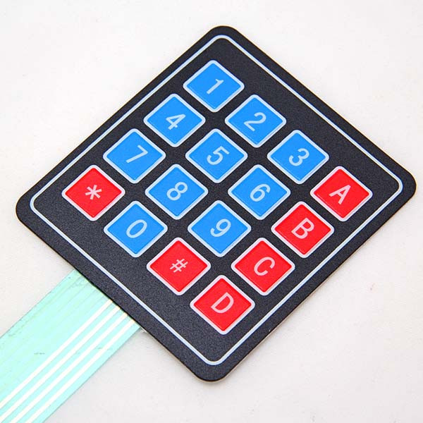
The 4×4 Matrix Keypad is a user-friendly input device consisting of 16 keys arranged in a 4×4 matrix. It is widely used in embedded systems, microcontroller projects, and DIY electronics for user input. Each key press is detected by scanning the matrix, allowing for efficient and reliable data entry. The keypad is compact, durable, and easy to integrate into various projects.
Key Features:
- Key Configuration: 4 rows and 4 columns, totaling 16 keys
- Interface: Matrix scanning
- Key Labels: Numeric and function keys (0-9, A-D, *, #)
- Compact Design: Suitable for handheld devices and small projects
- Durable: Made from high-quality materials for long-lasting use
- Flexible: Can be connected to any microcontroller or development board
- Low Power Consumption: Efficient operation with minimal power usage
Technical Specifications:
- Number of Keys: 16 (4×4 matrix)
- Operating Voltage: 3.3V to 5V
- Current Consumption: < 10mA
- Contact Resistance: ≤ 200 ohms
- Insulation Resistance: ≥ 100M ohms (at 250V DC)
- Operating Temperature Range: -20°C to +60°C
- Keypad Dimensions: 69mm x 69mm x 1.8mm
- Connection Type: 8-pin header
Applications:
- Embedded Systems: User input for microcontroller-based projects.
- DIY Electronics: Ideal for hobbyists and makers creating custom projects.
- Access Control: Use in security systems for code entry.
- Consumer Electronics: Keypad input for appliances and gadgets.
- Educational Projects: Commonly used in educational kits and learning modules.
Usage:
- Wiring: Connect the 8-pin header to the microcontroller or development board, ensuring correct row and column connections.
- Programming: Use libraries (e.g., Keypad library for Arduino) to read key presses and handle input.
- Integration: Incorporate the keypad into your project for reliable user input.
- Testing: Verify the functionality by pressing keys and checking the output.
Caution:
- Proper Connection: Ensure the keypad is connected correctly to avoid malfunction.
- Voltage Levels: Operate within the specified voltage range to prevent damage.
Datasheet:
For detailed technical specifications, refer to the 4×4 Matrix Keypad Datasheet.
|
The TS118-3 Non-Contact Infrared Temperature Sensor is designed to measure the temperature of an object or surface without physical contact. Utilizing infrared technology, this sensor detects thermal radiation emitted by the target and converts it into a temperature reading. It is suitable for various applications requiring temperature monitoring in hard-to-reach or hazardous environments.
Key Features:
- Non-contact temperature measurement
- Wide temperature range
- High accuracy and fast response time
- Compact and easy to integrate
- Digital output for easy interfacing with microcontrollers
- Built-in signal processing for reliable readings
Technical Specifications:
- Measurement Range: -40°C to +300°C
- Accuracy: ±1°C or ±1% of the reading (whichever is greater)
- Resolution: 0.1°C
- Emissivity: Adjustable or fixed (depending on model)
- Response Time: <500ms
- Output Type: Digital (I2C, SPI, or UART)
- Operating Voltage: 3.3V or 5V (depending on model)
- Operating Current: 10mA (typical)
- Operating Temperature Range: 0°C to +50°C (sensor environment)
- Storage Temperature Range: -20°C to +60°C
- Dimensions: 25mm x 20mm x 10mm (approximately, varies by manufacturer)
- Mounting Type: Typically surface mount or through-hole
Applications:
- Industrial Monitoring: Measures temperature of machinery, electrical components, and processes.
- Medical Equipment: Used in non-contact temperature measurement for medical diagnostics.
- HVAC Systems: Monitors temperature in heating, ventilation, and air conditioning systems.
- Safety and Maintenance: Detects overheating in electrical systems or equipment.
- Consumer Electronics: Integrated into devices for temperature measurement and control.
Usage:
- Mount the sensor in the desired location, ensuring it has a clear line of sight to the target.
- Connect the sensor to a microcontroller or data acquisition system using the appropriate communication interface.
- Calibrate the sensor if necessary, especially if adjustable emissivity is used.
- Read and process the temperature data from the sensor’s output.
Caution:
- Avoid direct exposure to strong light sources or reflective surfaces that can affect readings.
- Ensure proper thermal calibration for accurate measurements in different environments.
- Handle the sensor carefully to avoid damage to the optical components.
Datasheet:
For detailed technical specifications, refer to the TS118-3 Infrared Temperature Sensor Datasheet.
|
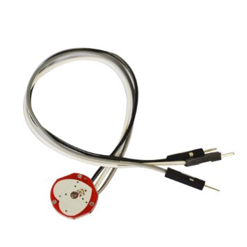
The Pulse/Heart Rate Sensor is designed to monitor and measure the heart rate or pulse rate of an individual. It utilizes optical or electrocardiographic (ECG) technology to detect the pulse waves or electrical signals associated with each heartbeat. This sensor is commonly used in medical devices, fitness trackers, and health monitoring systems to provide real-time data on heart rate and overall cardiovascular health.
Key Features:
- Real-time heart rate monitoring
- Accurate pulse detection
- Compact and easy to integrate
- Low power consumption
- Typically includes signal processing for noise reduction and accurate measurements
- Some models offer additional features like SpO2 measurement (oxygen saturation)
Technical Specifications:
- Measurement Range: Typically 30 BPM to 240 BPM (Beats Per Minute)
- Accuracy: ±2 BPM or ±2% (whichever is greater)
- Output Type: Analog (voltage signal) or Digital (PWM, UART, I2C, or SPI, depending on the model)
- Power Supply: 3.3V or 5V (depending on the model)
- Current Consumption: Typically around 5-10mA
- Operating Temperature Range: 0°C to +50°C
- Dimensions: Varies by model, typically around 20mm x 20mm x 10mm
- Mounting: Typically surface mount or clips onto a finger or earlobe for optical models
Applications:
- Fitness Tracking: Monitors heart rate during physical activities to assess fitness levels and workout intensity.
- Medical Devices: Provides heart rate data for diagnostic and monitoring purposes in medical equipment.
- Wearable Technology: Integrated into wristbands, smartwatches, and other wearable devices for health monitoring.
- Health Monitoring Systems: Used in remote health monitoring systems to track and analyze cardiovascular health.
Usage:
- Attach the sensor to the appropriate body part (e.g., fingertip, earlobe) or integrate it into your device.
- Connect the sensor to a microcontroller or data acquisition system using the appropriate interface (analog or digital).
- Calibrate the sensor if necessary to ensure accurate readings.
- Process the signal to extract heart rate information and use it as needed for your application.
Caution:
- Ensure proper attachment to the body part for accurate measurements.
- Avoid exposure to extreme temperatures or moisture that may affect sensor performance.
- Follow manufacturer guidelines for calibration and usage to ensure reliable results.
Datasheet:
For detailed technical specifications, refer to the Pulse/Heart Rate Sensor Datasheet.
|
|
The GY-906 MLX90614 Non-Contact Temperature Sensor Module is a highly accurate infrared thermometer designed for non-contact temperature measurements. This module uses the MLX90614 sensor, which can measure the temperature of objects without physical contact. It is ideal for applications such as industrial temperature monitoring, medical thermometers, home automation, and DIY electronics projects. The module provides both digital and analog outputs, making it easy to interface with microcontrollers and other digital devices.
Key Features:
- High accuracy non-contact temperature measurement
- Measures object and ambient temperature
- Digital output (I2C and PWM) and analog output
- Wide temperature measurement range
- Compact and easy to integrate into various projects
- Low power consumption
- Suitable for a variety of applications
Technical Specifications:
- Sensor Type: MLX90614 infrared thermometer
- Temperature Measurement Range: -70°C to +380°C for object temperature, -40°C to +85°C for ambient temperature
- Output: Digital (I2C, PWM) and analog voltage
- Power Supply: 3.3V to 5V DC
- Operating Temperature: -40°C to +85°C
Applications:
- Industrial temperature monitoring
- Medical thermometers
- Home automation
- HVAC systems
- DIY electronics projects
- Consumer electronics
Datasheet:
For detailed technical information, please refer to the GY-906 MLX90614 Datasheet.
|
The XY-TR01 is a versatile temperature and humidity control module equipped with a digital display. This module is designed for precise monitoring and control of environmental conditions, making it suitable for a wide range of applications, including HVAC systems, incubators, greenhouses, and other environments where maintaining specific temperature and humidity levels is crucial.
Key Features:
- Display: Digital display for real-time temperature and humidity readings.
- Sensor: High-accuracy temperature and humidity sensor.
- Control Outputs: Relay outputs for controlling heating, cooling, humidification, and dehumidification devices.
- Adjustable Settings: User-configurable temperature and humidity setpoints and hysteresis.
- Alarm Function: Audible and visual alarms for out-of-range conditions.
- User Interface: Intuitive interface with buttons for easy configuration and operation.
Technical Specifications:
- Power Supply: 12V DC
- Temperature Range: -40°C to 80°C (-40°F to 176°F)
- Humidity Range: 0% to 100% RH
- Temperature Accuracy: ±0.5°C
- Humidity Accuracy: ±3% RH
- Control Outputs: Relay outputs (typically up to 10A)
- Display Type: Digital LED or LCD display
- Dimensions: Compact design for easy installation
- Operating Environment: Indoor use, suitable for various controlled environments
Applications:
- HVAC Systems: For maintaining optimal temperature and humidity levels in residential and commercial HVAC systems.
- Incubators: Ensures precise control of temperature and humidity for successful incubation of eggs or other biological processes.
- Greenhouses: Helps maintain ideal growing conditions for plants by regulating temperature and humidity.
- Storage Facilities: Used in environments where specific temperature and humidity conditions are critical for preserving goods.
- DIY Projects: Ideal for hobbyists and makers creating custom environmental control systems.
Datasheet: For detailed technical information, refer to the XY-TR01 Temperature and Humidity Control Module datasheet.
|
The 125KHZ RFID Card is a contactless proximity card used for various identification and access control applications. It operates at a frequency of 125kHz and contains a unique identification number (UID) for each card. This card is durable and convenient, making it ideal for use in security systems, time and attendance tracking, and membership management.
Key Features:
- Operates at 125kHz frequency
- Durable PVC material
- Compatible with standard 125kHz RFID readers
- Unique identification number (UID) for each card
- Waterproof and tamper-resistant
- Long read range (up to 10 cm depending on the reader)
- No battery required (passive RFID technology)
Technical Specifications:
- Operating Frequency: 125kHz
- Material: PVC plastic
- Dimensions: 85.6mm x 54mm x 0.8mm (standard credit card size)
- Weight: Approximately 6g
- Read Range: Up to 10 cm (depending on the reader and environment)
- Data Storage: 64-bit read-only unique identifier (UID)
- Operating Temperature Range: -25°C to +85°C
- Color: Typically white, but may vary by manufacturer
- Waterproof: Yes
Applications:
- Access control systems
- Time and attendance tracking
- Membership management
- Asset tracking
- Secure entry systems
- Contactless payment systems
Usage:
- Integration:
- Enroll the RFID card in the desired RFID system by registering its unique identifier (UID) with the system’s database.
- Operation:
- Present the card to an RFID reader within the read range (up to 10 cm).
- The reader will capture the UID and communicate it to the control system for processing.
- Security:
- Use the card for secure access to restricted areas or for tracking attendance.
- Pair the card with a compatible RFID reader and control system for seamless operation.
Caution:
- Avoid exposing the card to extreme temperatures or harsh chemicals.
- Do not bend or apply excessive force to the card to prevent damage.
- Keep the card away from strong magnetic fields to ensure proper operation.
Datasheet:
For detailed technical specifications, refer to the manufacturer’s datasheet for your specific 125kHz RFID card model.
|
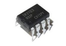
The IR2103PBF is a high voltage, high-speed power MOSFET and IGBT driver with independent high and low side referenced output channels. It is designed to drive high-side and low-side N-channel power MOSFETs or IGBTs in a half-bridge configuration. The device features a floating channel designed for bootstrap operation, allowing it to drive the high-side switch up to 600V.
Key Features:
- Gate drive supply range from 10V to 20V
- Floating channel can be used to drive an N-channel power MOSFET or IGBT in the high-side configuration up to 600V
- Gate drive outputs: 2A peak source, 2A peak sink
- Independent high-side and low-side channels
- Under-voltage lockout for both channels
- Logic input (IR2103) compatible with standard CMOS or LSTTL outputs
- Matched propagation delay for both channels
- Low side output in phase with input signal
- High side output out of phase with input signal
Technical Specifications:
- Supply Voltage (Vcc): 10V – 20V
- Floating Supply Voltage (Vb): up to 600V
- Logic Supply Voltage (Vss): -5V – 20V
- Output Source Current (Io+): 2A
- Output Sink Current (Io-): 2A
- Gate Drive Output Voltage (Vout): 10V – 20V
- Propagation Delay: 120ns (typical)
- Operating Temperature Range: -40°C to +125°C
- Package: PDIP-8
Applications:
- Motor drive applications
- Induction heating
- UPS systems
- DC-DC converters
- Switch-mode power supplies
Datasheet:
For detailed technical information, please refer to the IR2103PBF Datasheet.
|
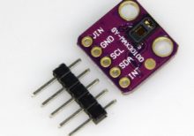
The GY-MAX30100 is a pulse oximeter and heart rate monitor module designed for use in wearable health devices and other applications requiring accurate measurement of heart rate and blood oxygen saturation levels. It integrates the MAX30100 sensor, which combines LED-based pulse oximetry and heart rate monitoring in a compact module.
Key Features:
- Sensor: MAX30100
- Functions: Measures heart rate and blood oxygen saturation (SpO2)
- Interface: I²C communication
- Operating Voltage: 1.8V to 3.3V
- Power Consumption: Low power consumption suitable for battery-operated devices
- On-Board LEDs: Red and IR LEDs for optical measurements
- Built-in Photodetector: For detecting light reflected from the skin
Technical Specifications:
- Operating Voltage: 1.8V to 3.3V
- Current Consumption: 0.2 mA (typical)
- Communication Interface: I²C
- Heart Rate Measurement Range: 30 bpm to 240 bpm
- SpO2 Measurement Range: 0% to 100%
- LED Wavelengths: Red (660 nm) and IR (940 nm)
- Resolution: 16-bit ADC for precise measurements
- Package: Typically comes as a small module with pin headers
Applications:
- Wearable Health Devices: Integrated into fitness trackers and smartwatches for monitoring heart rate and oxygen levels.
- Medical Monitoring: Used in portable and remote health monitoring systems.
- Fitness Tracking: Suitable for devices aimed at tracking physical activity and health metrics.
- Research and Development: Employed in prototypes and research projects related to health monitoring and wearable technology.
Datasheet:
For detailed technical information, refer to the MAX30100 Datasheet, as the GY-MAX30100 module utilizes this sensor.
|
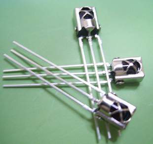
The TSOP 1838 is a compact IR (Infrared) receiver module designed for use in remote control systems. It can detect modulated IR signals at 38 kHz, making it ideal for applications such as remote control reception, IR data transmission, and IR-based communication systems. The TSOP 1838 provides high sensitivity and reliable performance in a small package.
Key Features:
- Pin diode and preamplifier in one package
- Modulated IR signal detection at 38 kHz
- High sensitivity and excellent noise immunity
- Low power consumption
- TTL and CMOS compatible output
- Internal filter for PCM frequency
- Improved shielding against electrical field disturbance
- Suitable for continuous and burst data transmission
Technical Specifications:
- Carrier Frequency: 38 kHz
- Supply Voltage: 2.7V to 5.5V
- Supply Current: 0.4 mA (typical)
- Peak Wavelength: 940 nm
- Reception Range: Up to 45 meters (with proper IR transmitter)
- Viewing Angle: ±45 degrees
- High-Level Output Voltage: ≥ Vcc – 0.2V
- Low-Level Output Voltage: ≤ 0.2V
- Output Pulse Width: Typically 400 µs
- Operating Temperature Range: -25°C to +85°C
- Package Type: 3-pin epoxy package
Applications:
- IR remote control systems
- Consumer electronics (TVs, VCRs, DVDs, audio equipment)
- Home automation
- IR data communication
- Infrared object detection
- Robotics
Usage:
- Connection:
- Connect the Vcc pin to a power supply (2.7V to 5.5V).
- Connect the GND pin to ground.
- Connect the OUT pin to the input of a microcontroller or other logic-level input device.
- Operation:
- When an IR signal at 38 kHz is received, the OUT pin goes low.
- When no IR signal is received, the OUT pin stays high.
- Use the output signal to control devices or process the data using a microcontroller.
- Interfacing:
- Interface the TSOP 1838 with a microcontroller to decode the received IR signals.
- Implement software to process the decoded IR signals for controlling various devices.
Caution:
- Ensure the IR receiver is not exposed to direct sunlight or strong ambient light sources, as this may affect its performance.
- Handle the module with care to avoid damage from electrostatic discharge (ESD).
Datasheet:
For detailed technical specifications, refer to the TSOP 1838 Datasheet.
|
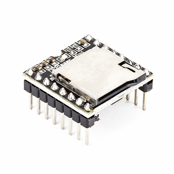
The DF Mini MP3 Player is a compact and cost-effective MP3 module that can be directly connected to a speaker. It can be used as a standalone module with battery, speaker, and push buttons, or in combination with an Arduino or other controller with RX/TX capabilities. It is widely used in applications like voice announcements, sound effects, and audio playback in various projects.
Key Features:
- Compact Size: Small form factor for easy integration
- Storage: Supports microSD cards up to 32GB
- File Format: MP3, WAV, and WMA file formats
- Built-in Amplifier: 3W amplifier for direct speaker connection
- Control Interface: Serial (UART), AD (Analog), or GPIO (General Purpose Input/Output)
- Power Supply: 3.2V to 5.0V DC
Technical Specifications:
- Operating Voltage: 3.2V to 5.0V DC
- Storage Medium: MicroSD card (up to 32GB)
- Audio Formats: MP3, WAV, WMA
- Amplifier: 3W built-in amplifier
- Control Interface:
- Serial (UART): For communication with microcontrollers
- AD (Analog): For controlling playback with potentiometers
- GPIO: For simple control using buttons or switches
- Output: Speaker (direct connection), headphone jack (if available)
- Dimensions: Compact and suitable for integration into various projects
Applications:
- Voice Announcements: Ideal for applications requiring voice prompts or messages.
- Sound Effects: Used in interactive displays, exhibits, and installations.
- Audio Playback: Suitable for DIY projects, toys, and educational tools.
- Embedded Systems: Integrated into products requiring audio feedback or instructions.
- Prototyping: Useful in developing and testing audio-based applications.
Datasheet:
For detailed technical information, refer to the DF Mini MP3 Player datasheet.
|
The Sim808 module is an integrated GSM/GPRS and GPS solution designed for versatile IoT and M2M applications. It combines GPS technology for satellite navigation and GSM/GPRS functionality for cellular communication in a compact form factor, making it ideal for various tracking and remote monitoring projects. This package includes both GPS and GPRS antennas for enhanced connectivity and performance.
Key Features:
- GSM/GPRS Module: Provides 850/900/1800/1900 MHz quad-band support for cellular communication.
- GPS Functionality: Integrated GPS receiver for accurate location tracking.
- Compact Design: Combines GSM/GPRS and GPS functions in a single module.
- Low Power Consumption: Efficient performance with minimal power usage.
- Antenna Included: Comes with GPS and GPRS antennas for reliable signal reception.
Technical Specifications:
- GSM/GPRS:
- Frequency Bands: 850/900/1800/1900 MHz
- GPRS Multi-slot Class 12
- GPRS Mobile Station Class B
- SIM Interface: 1.8V/3V
- Serial Communication: UART
- Data Transmission: SMS, MMS, GPRS, Internet
- GPS:
- Receiver Type: 22 tracking / 66 acquisition channels
- GPS L1 C/A Code
- Sensitivity: -165 dBm tracking
- Cold Start: <35s
- Hot Start: <1s
- Accuracy: <2.5m CEP
- Power Supply:
- Operating Voltage: 3.4V to 4.4V
- Current Consumption: <2.0mA in sleep mode
- Antenna:
- GPS Antenna: Included
- GPRS Antenna: Included
Applications:
- Vehicle tracking
- Asset tracking
- Remote monitoring systems
- IoT applications
- Security systems
Usage:
- Connect the Sim808 module to your microcontroller or computer using the appropriate serial interface.
- Attach the included GPS and GPRS antennas to the module.
- Insert a SIM card into the SIM card slot.
- Power the module using a suitable power supply within the specified voltage range.
- Use AT commands to communicate with the module for sending SMS, making calls, or obtaining GPS location data.
- Integrate the module into your application for real-time tracking and communication.
Caution:
- Ensure the power supply voltage is within the specified range to avoid damage.
- Handle the module with care to prevent static discharge and damage to the components.
- Use the included antennas for optimal signal reception and performance.
Datasheet: For more detailed technical information, refer to the Sim808 Datasheet.
|
The NRF24L01 is a highly integrated, ultra-low-power 2.4GHz RF transceiver suitable for wireless communication applications. It is designed to operate in the 2.4GHz ISM band and supports a wide range of applications, including wireless keyboards, mice, remote controls, toys, and other wireless data transfer systems. With its robust and efficient design, the NRF24L01 ensures reliable data transmission with minimal power consumption.
Key Features:
- Low Power Consumption: Ideal for battery-operated devices
- High Data Rate: Supports data rates up to 2 Mbps
- Multiple Communication Channels: Up to 125 RF channels
- Enhanced ShockBurst™: Automatic packet handling
- Compact Size: Easy integration into various applications
- Built-in Support: For address and CRC computation
- Wide Supply Voltage Range: 1.9 to 3.6V
Technical Specifications:
- Frequency Range: 2.4GHz ISM band
- Modulation: GFSK
- Data Rate: 250kbps, 1Mbps, 2Mbps
- Output Power: 0 dBm
- Sensitivity: -82 dBm at 2 Mbps, -85 dBm at 1 Mbps
- Current Consumption: 11.3mA TX at 0 dBm, 12.3mA RX at 2 Mbps
- Operating Voltage: 1.9 to 3.6V
- Interface: SPI
- Max Payload per Packet: 32 bytes
- Channels: 125
- Dimensions: 15 x 29mm
Applications:
- Wireless keyboards and mice
- Wireless remote controls
- Toys and gaming peripherals
- Wireless sensor networks
- Home automation systems
- Industrial control systems
Usage:
- Connect the NRF24L01 to a microcontroller via the SPI interface.
- Configure the transceiver settings (frequency, data rate, power level) using the microcontroller.
- Send and receive data wirelessly by writing to and reading from the appropriate registers.
- Ensure proper power supply and antenna connections for optimal performance.
Caution:
- Ensure the power supply voltage is within the specified range to avoid damage.
- Handle with care to prevent static discharge and damage to the components.
- Use appropriate antennas to maximize range and signal strength.
Datasheet: For more detailed technical information, refer to the NRF24L01 Datasheet.
|
The Raspberry Pi Zero W is a compact, low-cost single-board computer that includes built-in Wi-Fi and Bluetooth connectivity. It is designed for a wide range of applications, including embedded projects, IoT devices, and educational tools. The Raspberry Pi Zero W is highly valued for its small form factor and powerful performance relative to its size.
Key Features:
- Processor: 1GHz single-core ARM11 CPU
- Memory: 512MB RAM
- Wireless Connectivity: 802.11 b/g/n Wi-Fi, Bluetooth 4.1, Bluetooth Low Energy (BLE)
- Ports:
- Mini HDMI port for video output
- Micro USB OTG port for data and power
- Micro USB power port
- CSI camera connector
- GPIO: 40-pin GPIO header (unpopulated)
- Storage: MicroSD card slot for operating system and data storage
Technical Specifications:
- Processor: Broadcom BCM2835, 1GHz single-core ARM11
- Memory: 512MB LPDDR2 SDRAM
- Wireless Connectivity:
- 802.11 b/g/n Wi-Fi
- Bluetooth 4.1
- Bluetooth Low Energy (BLE)
- Video Output: Mini HDMI with 1080p60 support
- Audio Output: Via HDMI or I2S
- USB Ports:
- 1 x Micro USB OTG port
- 1 x Micro USB power port
- Camera Interface: CSI camera connector
- GPIO: 40-pin header with various functions (unpopulated)
- Storage: MicroSD card slot
- Dimensions: 65mm x 30mm x 5mm
- Power: 5V, 1.2A via Micro USB
Applications:
- Embedded Projects: Ideal for embedding into custom electronic devices due to its small size and wireless capabilities.
- IoT Devices: Suitable for Internet of Things (IoT) applications needing Wi-Fi and Bluetooth connectivity.
- Education: Used in educational environments to teach programming, electronics, and computer science.
- DIY Projects: Perfect for hobbyists creating custom gadgets, robots, and other interactive installations.
- Media Centers: Can be used to create low-cost media centers or streaming devices.
Datasheet:
For detailed technical information, refer to the official Raspberry Pi Zero W datasheet and documentation.
|
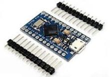
The Arduino Pro Micro is a compact and versatile microcontroller board based on the ATmega32U4 microchip. It is part of the Arduino family and designed for projects where space is limited. The Pro Micro board features built-in USB capabilities, allowing it to emulate a keyboard, mouse, or other USB devices, making it suitable for a wide range of applications including custom input devices and embedded systems.
Key Features:
- Microcontroller: ATmega32U4
- Operating Voltage: 5V
- Input Voltage (recommended): 7-12V
- Digital I/O Pins: 18
- Analog Input Pins: 9
- Flash Memory: 32 KB (ATmega32U4), of which 4 KB used by bootloader
- SRAM: 2.5 KB
- EEPROM: 1 KB
- Clock Speed: 16 MHz
- USB: Built-in USB functionality for direct connection to computers and emulation of USB devices
Technical Specifications:
- Dimensions: 33 mm x 18 mm
- Weight: Approximately 8 g
- Communication: UART, SPI, I2C, USB
- On-board LEDs: TX, RX, Power, and one user-defined LED
- Power:
- DC Current per I/O Pin: 40 mA
- DC Current for 3.3V Pin: 50 mA
- Connectors:
- USB Micro-B for programming and power
- 6-pin header for serial communication
- Pins for additional communication interfaces and power
Applications:
- Custom Input Devices: Can be used to create custom keyboards, mice, and other input devices.
- Embedded Systems: Suitable for small-scale embedded projects where USB connectivity is required.
- Prototyping: Ideal for rapid prototyping and development due to its compact size and USB capability.
- IoT Projects: Can be integrated into Internet of Things (IoT) devices for various control and monitoring applications.
- Wearables: Perfect for wearable electronics and projects requiring a small form factor.
Datasheet:
For detailed technical information, refer to the Arduino Pro Micro Datasheet.
|
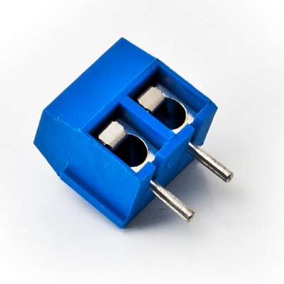
The 2-Way PCB Screw Terminal is a compact and reliable connector used to securely attach and disconnect wires on a printed circuit board (PCB). It features two screw terminals for connecting two wires, providing a stable and durable connection for various electronic and electrical applications. This type of terminal is commonly used in power distribution, signal connections, and modular systems.
Key Features:
- Two screw terminals for easy wire connection
- Suitable for use with PCB for secure mounting
- Provides a reliable and durable electrical connection
- Simple and convenient for quick wire insertion and removal
- Supports various wire gauges and types
- Compact design for space-saving on PCB
Technical Specifications:
- Number of Positions: 2
- Terminal Type: Screw
- Mounting Type: PCB (Printed Circuit Board)
- Wire Gauge Range: Typically 22-12 AWG (varies by manufacturer)
- Insulation Material: Polyamide (PA) or other suitable insulating materials
- Terminal Material: Brass or copper with tin plating
- Operating Voltage: Typically up to 300V (depends on the specific terminal rating)
- Operating Temperature Range: -40°C to +105°C
- Package Type: Typically available in strips or individual connectors
Applications:
- Power supply connections
- Signal wiring and distribution
- Modular and expandable systems
- Industrial equipment
- Consumer electronics
Usage:
- Mount the 2-Way PCB Screw Terminal onto the PCB by inserting it into the designated holes.
- Secure the terminal to the PCB by soldering the pins or using mechanical locking methods (if applicable).
- Strip the insulation from the wires to the appropriate length.
- Insert the stripped wires into the terminal and tighten the screws to secure the wires in place.
Caution:
- Ensure the terminal is rated for the voltage and current levels used in your application.
- Avoid over-tightening the screws to prevent damage to the terminal or wires.
- Verify proper wire insulation stripping to ensure reliable connections.
Datasheet:
For detailed technical specifications, refer to the 2-Way PCB Screw Terminal Datasheet.
|
The Professional Soldering Iron 60W is designed for precision soldering tasks in electronics and electrical work. Its high power output ensures quick heating and efficient soldering, making it ideal for both hobbyists and professionals.
Key Features:
- High Power: 60W output for fast heating and consistent performance.
- Adjustable Temperature Control: Allows precise temperature adjustments for different soldering tasks.
- Ergonomic Design: Comfortable grip for extended use and improved control.
- Fast Heat-Up: Quickly reaches operating temperature to reduce waiting time.
- Durable Tip: Long-lasting soldering tip designed for reliable performance.
Technical Specifications:
- Power: 60W
- Temperature Range: 200°C to 450°C (392°F to 842°F)
- Tip Type: Replaceable
- Handle Type: Ergonomic, heat-resistant
- Heat-Up Time: < 30 seconds
- Cord Length: 1.2 meters
- Input Voltage: 220V AC (or according to regional standards)
- Weight: Approximately 150 grams
Applications:
- Electronics assembly and repair
- PCB soldering
- Electrical connections
- Fine precision soldering work
Usage:
- Plug the soldering iron into a suitable power outlet.
- Set the desired temperature using the temperature control knob.
- Wait for the iron to reach the set temperature before using it for soldering.
- Use the soldering tip to apply solder to the joints or components as needed.
Caution:
- Handle with care as the soldering iron becomes very hot.
- Ensure proper ventilation while soldering to avoid inhaling fumes.
- Allow the soldering iron to cool down before storing.
|
The DS1307 RTC (Real-Time Clock) Module is a compact and accurate timekeeping module used to keep track of time in electronic systems. It is based on the DS1307 IC, which provides accurate timekeeping capabilities and can operate with a battery backup to maintain time during power outages. This module is widely used in various applications including clocks, data loggers, and embedded systems.
Key Features:
- Accurate timekeeping with a real-time clock (RTC) IC
- Battery backup to maintain time during power loss
- Easy-to-use I²C interface for communication with microcontrollers
- Provides seconds, minutes, hours, day, date, month, and year
- Low power consumption for battery operation
- Integrated crystal oscillator for precise timekeeping
- Compact and easy to integrate into projects
Technical Specifications:
- IC Used: DS1307
- Interface: I²C (2-wire)
- Operating Voltage: 5V (typical)
- Battery Backup: CR2032 or equivalent lithium battery (not included)
- Accuracy: ±2 minutes per month at 25°C
- Clock Frequency: 32.768 kHz (crystal oscillator)
- Operating Temperature Range: -40°C to +85°C
- Dimensions: Varies by manufacturer (common size: 40mm x 20mm)
- Weight: Varies by manufacturer (typically around 10g)
Applications:
- Real-time clocks in electronic devices
- Data logging and timestamping
- Time-based triggering in automation systems
- Embedded systems requiring accurate timekeeping
- Educational projects and prototypes
Usage:
- Connect the DS1307 RTC Module to your microcontroller via the I²C interface (SDA and SCL lines).
- Insert a compatible lithium battery into the module to provide backup power.
- Use the appropriate library or driver to interface with the DS1307 and set the current date and time.
- Retrieve and update the time as needed for your application.
Caution:
- Ensure the battery is properly installed to maintain time during power outages.
- Handle the module with care to avoid damaging the crystal or solder connections.
- Verify I²C connections to avoid communication issues.
Datasheet:
For detailed technical specifications, refer to the DS1307 Datasheet.
|
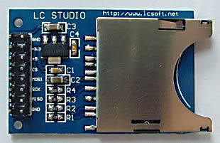
The SD Card Module is a compact and efficient solution for adding storage capabilities to your microcontroller or development board projects. It allows you to read from and write to SD cards, making it ideal for data logging, file storage, and other applications requiring large amounts of memory. The module supports various SD card formats and interfaces seamlessly with popular microcontrollers like Arduino, Raspberry Pi, and others.
Key Features:
- Storage: Supports SD, SDHC, and MicroSD (with adapter) cards
- Interface: SPI interface for easy integration
- Voltage Compatibility: Operates at 3.3V and 5V
- Onboard 3.3V Regulator: Ensures stable operation
- Card Detection: Built-in card detection switch
- Compact Design: Small footprint for easy incorporation into projects
- File System: Compatible with FAT16 and FAT32 file systems
Technical Specifications:
- Supported Cards: SD, SDHC, MicroSD (with adapter)
- Operating Voltage: 3.3V/5V
- Interface: SPI
- Current Consumption: < 100mA
- File System: FAT16, FAT32
- Dimensions: 42mm x 24mm x 12mm
Applications:
- Data Logging: Store sensor data and logs in embedded systems.
- File Storage: Save files for multimedia applications and projects.
- Firmware Updates: Load new firmware from the SD card for microcontrollers.
- DIY Projects: Perfect for hobbyists needing additional storage.
- Educational Projects: Commonly used in learning modules for data storage and retrieval.
Usage:
- Wiring: Connect the SD card module to your microcontroller using the SPI interface (CS, MOSI, MISO, SCK, VCC, GND).
- Power Supply: Ensure the module is powered with 3.3V or 5V, as required.
- Card Insertion: Insert a formatted SD card into the module.
- Programming: Use libraries (e.g., SD library for Arduino) to initialize the SD card and read/write data.
- Data Handling: Store or retrieve data files from the SD card as needed by your application.
Caution:
- Voltage Levels: Ensure proper voltage levels to avoid damaging the module.
- Handling SD Cards: Handle SD cards with care to prevent data loss or corruption.
Datasheet:
For detailed technical specifications, refer to the SD Card Module Datasheet.
|
The XL6009 DC-DC Boost Converter with Voltmeter Display is a high-efficiency, adjustable boost converter module designed to step up DC voltage from a lower level to a higher one. This module integrates a built-in voltmeter display for real-time voltage monitoring, making it ideal for use in various power supply applications, including battery-powered devices, LED drivers, and other electronic projects.
Key Features:
- DC-DC boost converter based on the XL6009 IC
- Integrated digital voltmeter display for monitoring output voltage
- Wide input voltage range for flexibility in power sources
- High efficiency with low power loss
- Adjustable output voltage with precision control
- Compact and durable design for various applications
Technical Specifications:
- IC Type: XL6009
- Input Voltage Range: 5V to 32V
- Output Voltage Range: Adjustable from 5V to 35V
- Output Current: Up to 4A (depending on cooling and input conditions)
- Efficiency: Up to 94% (depending on input/output conditions)
- Display Type: Digital voltmeter
- Display Voltage Range: 0V to 40V
- Adjustable Output Voltage: Yes, using a potentiometer
- Operating Temperature Range: -40°C to +85°C
- Size: Approximately 60mm x 35mm x 20mm
Applications:
- Power supply for battery-operated devices
- LED drivers
- DC-DC converters for custom electronic projects
- Powering electronic circuits requiring stable and adjustable voltage
- Voltage regulation in various electronic systems
Usage:
- Connect the input terminals to the power source, ensuring correct polarity.
- Use the onboard potentiometer to adjust the output voltage to the desired level.
- Monitor the output voltage using the integrated voltmeter display.
- Connect the load to the output terminals, ensuring the load does not exceed the maximum current rating of the module.
- Verify that the module operates within its specified temperature range and conditions.
Caution:
- Ensure proper input and output connections to avoid damage or malfunction.
- Avoid exceeding the maximum input voltage or output current ratings.
- Use appropriate heat dissipation techniques if operating under high load conditions to prevent overheating.
Datasheet:
For detailed technical specifications, refer to the XL6009 Datasheet.
|
The TCS230 is a color sensor used to detect and measure the color of an object. It features an array of photodiodes with red, green, and blue filters, along with a built-in RGB color sensing element. The sensor is widely used in various applications, including color recognition, sorting systems, and educational projects.
Key Features:
- Integrated RGB color sensing
- High resolution with 8×8 photodiode array
- Adjustable light sensitivity
- Provides digital output (frequency) proportional to the color intensity
- Simple interfacing with microcontrollers
- Compact size and low power consumption
Technical Specifications:
- Photodiode Array: 8×8 pixels (64 total)
- Output: Digital frequency output (proportional to color intensity)
- Operating Voltage: 2.7V to 5.5V DC
- Current Consumption: Approximately 10mA
- Light Sensitivity: Adjustable via external resistors
- Temperature Range: -40°C to +85°C
- Dimensions: 13.8 mm x 13.8 mm
- Package: 8-pin LCC (Leadless Chip Carrier)
Applications:
- Color Recognition: Detect and identify colors in various applications
- Sorting Systems: Sort objects based on color for automation processes
- Educational Projects: Teach principles of color sensing and electronics
- Robotics: Use in robots for color-based tasks and navigation
- Quality Control: Check color consistency in manufacturing processes
Usage:
- Connect the TCS230 sensor to a microcontroller or development board according to the pinout configuration.
- Configure the sensor’s light sensitivity using external resistors if needed.
- Read the frequency output corresponding to the intensity of each color (red, green, blue) using the microcontroller.
- Process the color data for your application, such as color detection or sorting.
Caution:
- Ensure the sensor is connected correctly to avoid damage.
- Avoid exposing the sensor to direct sunlight or intense light sources to prevent saturation and inaccurate readings.
- Handle with care to avoid damage to the delicate photodiode array.
Datasheet:
For detailed technical specifications, refer to the TCS230 Datasheet.
|
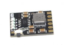
Description: The CD42 2A LiPo Charger Discharging and Protection Module is a versatile module designed for charging, discharging, and protecting 2-cell lithium polymer (LiPo) battery packs. It integrates charging management, discharge control, and comprehensive protection features to ensure safe and efficient operation of LiPo batteries. This module is suitable for applications requiring reliable battery management, such as RC models, drones, portable electronics, and DIY projects.
Key Features:
- Supports 2-cell LiPo battery packs (7.4V nominal)
- Integrated charging and discharging functions
- Built-in protection against overcharge, overdischarge, overcurrent, and short-circuit
- LED indicators for charging and battery status
- Micro USB interface for convenient power input
- Adjustable charging current up to 2A
- Compact and easy to integrate into various projects
- Reverse polarity protection for added safety
Technical Specifications:
- Battery Type: 2-cell LiPo (7.4V nominal)
- Charging Voltage: 8.4V
- Charging Current: Up to 2A (adjustable)
- Discharge Current: Up to 2A (limited by onboard MOSFET)
- Protection Features: Overcharge, overdischarge, overcurrent, short-circuit, reverse polarity
- Input Interface: Micro USB
- Dimensions: Compact size suitable for integration
- Weight: Lightweight for ease of handling
Applications:
- RC models (cars, boats, airplanes)
- Drones and UAVs (Unmanned Aerial Vehicles)
- Portable electronics (power banks, handheld devices)
- DIY battery pack projects
- Educational projects involving battery management
Datasheet: For detailed technical information, refer to the CD42 2A LiPo Charger Discharging and Protection Module Datasheet.
|
Description:
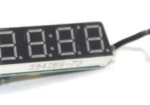
The Seven Segment High Precision Electronic Clock is a digital timekeeping device that displays the current time with high accuracy. Utilizing seven-segment LED displays, it provides a clear and easily readable representation of hours, minutes, and seconds. This clock is suitable for various applications, including industrial environments, educational settings, and personal use.
Key Features:
- High Precision Timekeeping: Ensures accurate time display with minimal drift over time.
- Seven-Segment LED Display: Provides clear and bright time readouts, easily visible from a distance.
- User-Friendly Interface: Simple controls for time setting and adjustments.
- Durable Construction: Built to withstand continuous use in various environments.
- Compact Design: Easily integrates into different spaces without occupying much room.
Technical Specifications:
- Display Type: Seven-segment LED
- Power Supply: Typically 5V DC
- Accuracy: ±1 second per month
- Operating Temperature Range: 0°C to +50°C
- Dimensions: Compact size for versatile installation options
- Weight: Lightweight design for ease of handling and mounting
Applications:
- Industrial Timing: Used in manufacturing plants and workshops for precise timekeeping.
- Educational Settings: Ideal for classrooms and laboratories for teaching time management and electronics.
- Personal Use: Suitable for home and office use to keep accurate track of time.
- Public Spaces: Can be installed in public areas such as lobbies, halls, and waiting rooms for time display.
|
The Raspberry Pi 5 Inch Touch Screen Display is a high-resolution display designed for use with the Raspberry Pi single-board computer. It features a capacitive touch screen for an intuitive and interactive user experience, making it ideal for a wide range of projects, including embedded applications, digital signage, and portable computing devices.
Key Features:
- 5-inch display with a high-resolution of 800×480 pixels
- Capacitive touch screen with multi-touch capability
- Supports backlight control
- Compatible with Raspberry Pi models
- Easy integration with GPIO pins
- HDMI input for high-quality video display
- USB interface for touch control
Technical Specifications:
- Display Size: 5 inches
- Resolution: 800×480 pixels
- Touch Screen Type: Capacitive
- Touch Points: 10-point multi-touch
- Interface: HDMI (video), USB (touch)
- Backlight Control: Yes
- Power Supply: 5V DC via micro USB
- Dimensions: 121.11mm x 76.96mm
- Operating Temperature Range: -20°C to 70°C
Applications:
- Portable computing devices
- Embedded systems
- Digital signage
- Home automation interfaces
- Educational tools and kits
- Prototyping and development projects
Datasheet:
For detailed technical specifications, refer to the Raspberry Pi 5 Inch Touch Screen Display Datasheet.
|
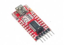
The USB to TTL FT232 is a USB-to-serial converter module that uses the FTDI FT232 chip to convert USB signals to TTL (Transistor-Transistor Logic) level serial communication. This module is commonly used to interface USB-enabled devices with TTL serial devices, such as microcontrollers and development boards. It provides a convenient way to connect devices that use TTL serial communication to a computer via a USB port.
Key Features:
- Chip: FTDI FT232
- Interface: USB to TTL serial (UART)
- Data Rate: Up to 3 Mbps
- Operating Voltage: 3.3V or 5V TTL levels (configurable)
- Driver Support: Compatible with major operating systems including Windows, macOS, and Linux
- Connector: Typically includes a USB Type-A or Type-B connector and TTL pins (TX, RX, VCC, GND)
- LED Indicators: Often includes LEDs to indicate power and data transmission
Technical Specifications:
- USB Interface: USB 2.0
- TTL Levels: 3.3V or 5V (depends on the module configuration)
- Data Rate: Up to 3 Mbps
- Driver Support: FTDI drivers for Windows, macOS, and Linux
- Pin Configuration:
- TX: Transmit data
- RX: Receive data
- VCC: Power supply (3.3V or 5V)
- GND: Ground
- Power Supply: Powered via USB (typically 5V from USB)
Applications:
- Microcontroller Programming: Used for programming and debugging microcontrollers that use TTL serial communication.
- Serial Communication: Facilitates communication between USB-equipped computers and serial devices.
- Embedded Systems: Connects embedded systems to PCs for data exchange and control.
- Prototyping: Commonly used in electronic prototypes to bridge the gap between USB and TTL serial interfaces.
Datasheet:
For detailed technical information, refer to the FTDI FT232 Datasheet, which provides comprehensive details on specifications, pin configuration, and operation.
|
The SQ11 Mini 1080p camera is a compact and lightweight surveillance camera capable of recording high-definition video. It is known for its small size, making it ideal for discreet monitoring and recording in various settings.
Key Features:
- Video Resolution: Records video in Full HD 1080p resolution, ensuring clear and detailed footage.
- Compact Design: Small and portable, suitable for covert surveillance and mobile applications.
- Motion Detection: Supports motion detection mode, triggering recording when motion is detected.
- Night Vision: Equipped with infrared LEDs for night vision capabilities, allowing recording in low-light conditions.
- Wide-Angle Lens: Offers a wide-angle lens to capture a broader view of the surroundings.
- Loop Recording: Supports loop recording, overwriting older files when the memory card is full to ensure continuous recording.
- Storage: Uses MicroSD cards for storage, typically supporting capacities up to 32GB (MicroSD card not included).
- Power Supply: Powered via USB cable or by a built-in rechargeable battery for portable use.
- Easy Operation: Simple operation with minimal controls for ease of use.
- Versatile Mounting Options: Includes various mounting accessories for flexible placement and installation.
Applications:
- Home Security: Monitoring indoor spaces such as homes, offices, or nurseries.
- Car Dashcam: Recording driving footage for safety and security purposes.
- Sports Action: Capturing outdoor activities such as biking, hiking, or sports events.
- Surveillance: Monitoring areas covertly or for evidence collection.
- Personal Use: Recording personal moments, vlogs, or travel experiences.
|
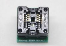
The SOP8 to DIP8 IC Socket Adapter is designed to facilitate the use of SOP8 (Small Outline Package) integrated circuits with DIP8 (Dual Inline Package) sockets. This adapter is ideal for prototyping and testing applications where surface-mount devices need to be used with through-hole PCB designs.
Key Features:
- Easy Conversion: Converts SOP8 ICs to DIP8 format for compatibility with standard DIP sockets.
- High-Quality Construction: Made from durable materials to ensure reliable connections.
- Gold-Plated Contacts: Provides excellent conductivity and corrosion resistance.
- Compact Design: Fits easily onto breadboards and other prototyping platforms.
- Reusable: Can be used multiple times for different projects and ICs.
Technical Specifications:
- Package Type: SOP8 to DIP8
- Pin Pitch (SOP): 1.27mm
- Pin Pitch (DIP): 2.54mm
- Material: FR4 PCB, Gold-plated contacts
- Dimensions: Varies by model
- Weight: Lightweight design
- Temperature Range: -40°C to +85°C
- Mounting Type: Through-hole
Applications:
- Prototyping: Allows for easy testing of SOP8 ICs on breadboards and standard PCBs.
- Development: Facilitates the development of circuits using surface-mount devices.
- Repair and Replacement: Useful for replacing SOP8 ICs with DIP8 ICs in existing designs.
- Education: Ideal for educational purposes to demonstrate the use of different IC packages.
|
The RC522 RFID Module Kit is a complete solution for adding RFID functionality to your projects. The module operates at 13.56MHz and uses the MFRC522 IC for communication with RFID cards and tags. It is designed for easy integration with microcontroller platforms like Arduino, making it ideal for access control, attendance systems, and other identification applications.
Key Features:
- Operates at 13.56MHz frequency
- Compatible with ISO/IEC 14443 Type A cards
- Supports MIFARE1 S50, MIFARE1 S70, MIFARE Ultralight, MIFARE Pro, and MIFARE DESFire cards
- SPI, I2C, and UART communication interfaces
- Low power consumption
- High data transfer rate (up to 10 Mbit/s)
- Compact design and easy to use
- Comes with RFID cards and key fobs
Technical Specifications:
- Operating Frequency: 13.56MHz
- IC Chip: MFRC522
- Communication Interfaces: SPI, I2C, UART
- Power Supply Voltage: 3.3V
- Current Consumption: 13-26mA
- Read Range: Up to 5 cm (depending on the antenna size and tag type)
- Dimensions: 40mm x 60mm x 5mm
Kit Components:
- RC522 RFID Module
- 1 x MIFARE 1K S50 RFID Card
- 1 x RFID Key Fob
- Header pins for connection
- Jumper wires for easy interfacing
Applications:
- Access control systems
- Time and attendance tracking
- Contactless payment systems
- Inventory management
- Asset tracking
- DIY electronics projects
Usage:
- Wiring:
- Connect the RC522 RFID module to your microcontroller platform using SPI, I2C, or UART interfaces. For Arduino, the typical SPI connections are:
- VCC to 3.3V
- GND to GND
- RST to Pin 9
- IRQ (not used)
- MISO to Pin 12
- MOSI to Pin 11
- SCK to Pin 13
- SDA (SS) to Pin 10
- Programming:
- Install the necessary libraries (e.g., MFRC522 library for Arduino).
- Use example code to initialize the module and read RFID tags or cards.
- Testing:
-
- Present an RFID card or key fob to the module and observe the UID output on the serial monitor.
Caution:
- Ensure proper handling to avoid damage from electrostatic discharge (ESD).
- Verify power supply requirements to prevent damage to the module.
- Keep the module away from strong electromagnetic fields to ensure reliable operation.
Datasheet:
For detailed technical specifications, refer to the MFRC522 Datasheet.
|
|
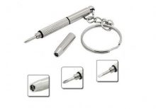
The Ruike 5×4 inch star screwdriver is a precision tool designed for use in various electronics and hardware applications. Featuring a comfortable yellow and black handle, this screwdriver provides excellent grip and control, making it ideal for both professional and DIY use. The star (Torx) head design ensures compatibility with star-shaped screws commonly found in many devices.
Key Features:
- Type: Star (Torx) screwdriver
- Size: 5×4 inch
- Handle: Ergonomic yellow and black handle for comfortable use
- Material: High-quality steel for durability and long life
- Precision Tip: Ensures a perfect fit with star-shaped screws
- Applications: Suitable for electronics, appliances, and other precision hardware
Technical Specifications:
- Length: 5 inches
- Handle Length: 4 inches
- Tip Size: T5 (Star/Torx)
- Material:
- Blade: Hardened steel for strength and durability
- Handle: Durable plastic with a non-slip grip
- Color: Yellow and black
- Weight: Approximately 50g
Applications:
- Electronics Repair: Ideal for opening and repairing small electronic devices such as smartphones, tablets, and laptops.
- Appliance Maintenance: Suitable for servicing small household appliances.
- DIY Projects: Perfect for various DIY projects requiring precision tools.
- Assembly and Disassembly: Useful for assembling and disassembling products with star-shaped screws.
|
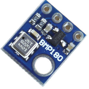
The BMP180 is a high-precision digital barometer and altitude sensor from Bosch, designed to measure atmospheric pressure and temperature. It is commonly used in applications requiring accurate altitude measurement and weather monitoring. The BMP180 provides reliable data for various applications including GPS, weather stations, and altitude tracking in wearable devices.
Key Features:
- Accurate barometric pressure and temperature measurement
- Digital interface with I²C or SPI communication
- High resolution with 0.03 hPa pressure measurement accuracy
- Compact and low-power design
- Built-in calibration for precise readings
- Wide operating temperature range
Technical Specifications:
- Sensor Type: Barometric Pressure and Temperature Sensor
- Communication Protocol: I²C (default), SPI (optional)
- Pressure Range: 300 hPa to 1100 hPa
- Pressure Accuracy: ±1 hPa (typical)
- Temperature Range: -40°C to +85°C
- Temperature Accuracy: ±1°C
- Resolution: 0.03 hPa for pressure
- Operating Voltage: 1.8V to 3.6V
- Current Consumption: 3µA (typical in sleep mode), 10µA (typical in measurement mode)
- Package Type: LGA-8 (Leadless Grid Array)
Applications:
- Altitude and weather tracking
- GPS altitude calibration
- Pressure-based data logging
- Environmental monitoring
- Wearable devices and consumer electronics
Usage:
- Connect the BMP180 sensor to your microcontroller or development board using I²C or SPI interface.
- Power the sensor with a voltage within the operating range (1.8V to 3.6V).
- Use the appropriate library or driver for the I²C or SPI protocol to interface with the sensor.
- Retrieve and process pressure and temperature data according to your application needs.
Caution:
- Ensure proper voltage supply to avoid damage to the sensor.
- Handle the sensor carefully to prevent mechanical damage or contamination.
- Verify correct wiring and communication protocol settings for accurate readings.
Datasheet:
For detailed technical specifications, refer to the BMP180 Datasheet.
|
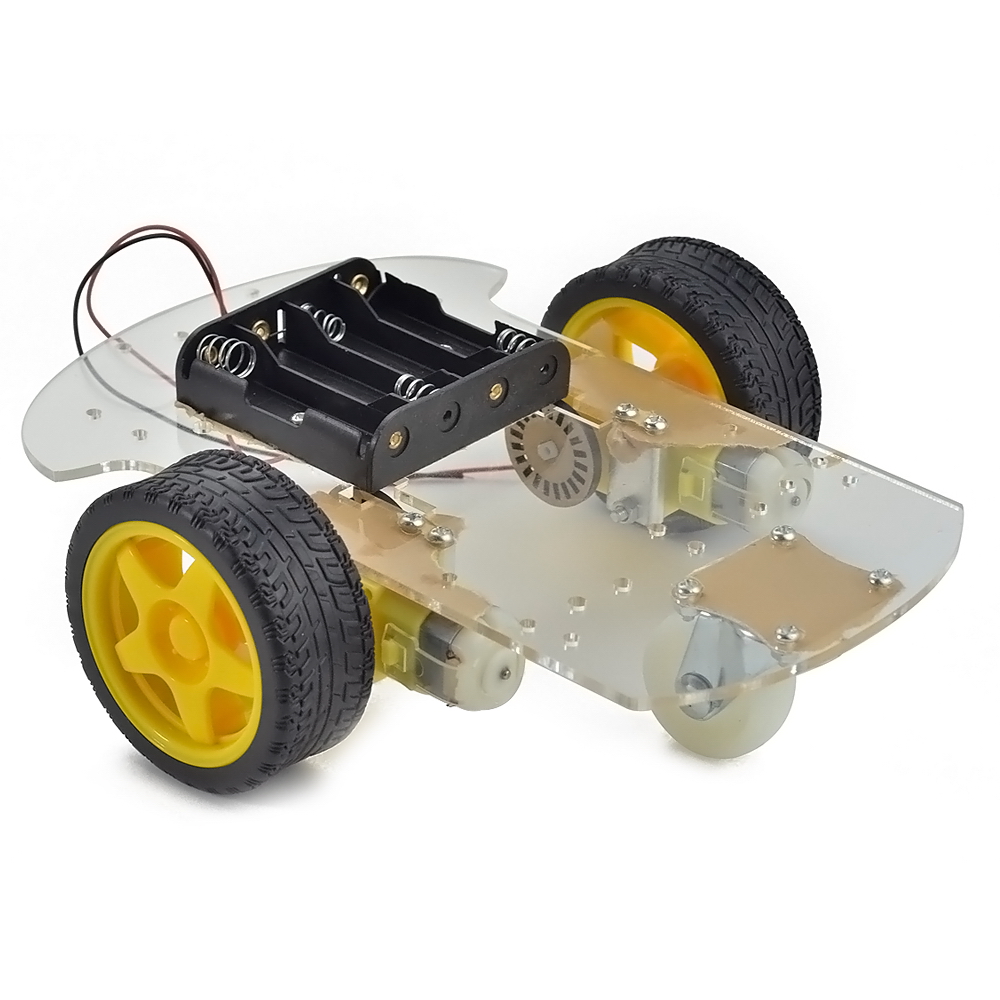
The 2WD Motor Chassis is a versatile and robust platform designed for building small robotic vehicles. This chassis kit includes two DC motors with wheels and a sturdy frame, providing an excellent foundation for creating custom robots, educational projects, and prototyping. The design allows easy integration with various microcontrollers, sensors, and other electronic components.
Key Features:
- Sturdy and durable construction
- Two high-quality DC motors with wheels
- Easy to assemble and modify
- Compatible with various microcontrollers and sensors
- Ample space for mounting additional components
- Suitable for indoor and outdoor use
Technical Specifications:
- Material: Acrylic or metal (varies by model)
- Dimensions: Approx. 170mm x 100mm x 60mm (assembled size may vary)
- Weight: Approx. 200g (including motors and wheels)
- Motors: Two DC motors (typically 3V-6V)
- Wheels: Two rubber wheels, diameter approx. 65mm
- Chassis Frame: Pre-drilled holes for easy component mounting
- Power Supply: Varies based on motor specifications (typically 3V-6V)
- Load Capacity: Suitable for small to medium-sized robots
- Operating Temperature Range: -10°C to +50°C
Applications:
- Educational Projects: Ideal for teaching robotics and electronics in schools and universities.
- Prototyping: Useful for developing and testing robotic designs and concepts.
- DIY Robotics: Perfect for hobbyists and enthusiasts building custom robots.
- Obstacle Avoidance Robots: Suitable for creating robots that navigate through obstacles.
- Line Following Robots: Can be used to build robots that follow predefined paths.
Usage:
- Assemble the chassis by attaching the motors and wheels to the frame.
- Connect the motors to your microcontroller or motor driver.
- Mount any additional sensors, controllers, or electronic components.
- Power the motors and program your microcontroller to control the chassis.
- Test and adjust the configuration to suit your specific robotic application.
Caution:
- Ensure proper handling and assembly to avoid damaging the chassis or motors.
- Verify the power supply voltage and current specifications before powering the motors.
- Avoid excessive loads that may strain the motors or chassis structure.
- Follow safety guidelines when working with electronic components and tools.
Datasheet:
For detailed technical specifications, refer to the 2WD Motor Chassis Datasheet.
|
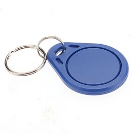
The 125KHZ RFID Key Chain is a compact and durable radio-frequency identification (RFID) device used for access control and identification applications. It operates at a frequency of 125kHz and is compatible with standard RFID readers. The key chain format makes it convenient to carry and use for various applications such as security systems, attendance tracking, and asset management.
Key Features:
- Operates at 125kHz frequency
- Durable and compact key chain design
- Compatible with standard RFID readers
- Unique identification number (UID) for each key chain
- Waterproof and shock-resistant
- Long read range (up to 10 cm depending on the reader)
- No battery required (passive RFID technology)
Technical Specifications:
- Operating Frequency: 125kHz
- Material: ABS plastic
- Dimensions: Approximately 40mm x 32mm x 4mm
- Weight: Approximately 6g
- Read Range: Up to 10 cm (depending on the reader and environment)
- Data Storage: 64-bit read-only unique identifier (UID)
- Operating Temperature Range: -25°C to +85°C
- Color: Typically blue, but may vary by manufacturer
- Waterproof: Yes
Applications:
- Access control systems
- Time and attendance tracking
- Membership management
- Asset tracking
- Secure entry systems
- Contactless payment systems
Usage:
- Integration:
- Enroll the RFID key chain in the desired RFID system by registering its unique identifier (UID) with the system’s database.
- Operation:
- Present the key chain to an RFID reader within the read range (up to 10 cm).
- The reader will capture the UID and communicate it to the control system for processing.
- Security:
- Use the key chain for secure access to restricted areas or for tracking attendance.
- Pair the key chain with a compatible RFID reader and control system for seamless operation.
Caution:
- Avoid exposing the key chain to extreme temperatures or harsh chemicals.
- Do not bend or apply excessive force to the key chain to prevent damage.
- Keep the key chain away from strong magnetic fields to ensure proper operation.
Datasheet:
For detailed technical specifications, refer to the manufacturer’s datasheet for your specific 125kHz RFID key chain model.
|
