Subtotal: ₦2,800.00
ESP32 C3 Supermini with built-in 4M flash memory
₦8,000.00
ESP32-C3-SuperMini is a tiny in size with castellated holes, making them easy to integrate into other host boards.
The ESP32-C3-SuperMini features a Type-C USB connector and makes most of its pins accessible in a compact design. It uses the ESP32-C3FN4 chip, which includes low-power WiFi and Bluetooth 5, along with 4MB of flash memory. This chip also has built-in security features like an encryption accelerator, random number generator (RNG), hardware-based message authentication code (HMAC), and digital signature modules, making it suitable for secure IoT applications.
Additionally, the ESP32-C3-SuperMini supports various power-saving modes, making it ideal for IoT projects, mobile devices, wearable tech, and smart home devices.
In stock

Features
- Low-power SoC equipped with RISC-V 32-bit single-core processor, up to 160MHz main frequency.
- Supports 2.4GHz Wi-Fi (802.11 b/g/n) and Bluetooth® 5 (LE).
- 400KB of SRAM and 384KB ROM, and 4MB of onboard Flash memory.
- Castellated module and onboard ceramic antenna, allow soldering direct to carrier boards.
- Supports flexible clock, module power supply independent setting, and other controls to realize low power consumption in different scenarios.
- Integrated with USB serial port full-speed controller, 15 × GPIO pins allow flexible configuring pin functions.
- 3 × SPI, 1 × I2C, 2 × UART, 1 × I2S, 2 × ADC, etc.
Hardware Description
Antenna Placement: When using daughterboards, avoid covering the ceramic antenna with any components such as PCBs, metal, or plastic, as this could interfere with the signal.
GPIO Pins: GPIO12 to GPIO17 are not exposed because they are used internally for the 4MB Flash memory.
USB to UART Chip: The ESP32-C3-Mini does not use a USB to UART bridge chip. When flashing firmware, you need to hold the BOOT button (connected to GPIO9) while connecting the board via the Type-C USB cable. This puts the device into the download mode necessary for flashing firmware.
UART Pins: The “TX” and “RX” markings on the board indicate the default UART0 pins, where TX is connected to GPIO21 and RX to GPIO20
Pinout
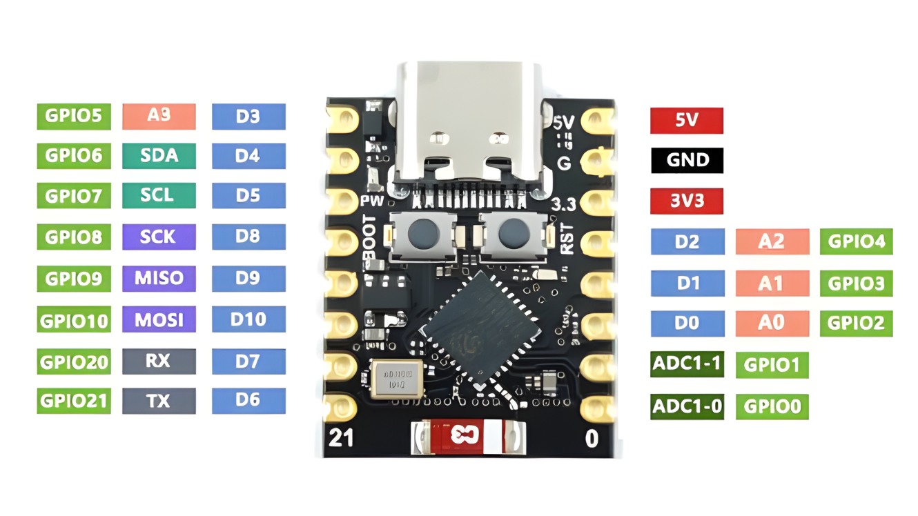
- 3V3 – Provides a stable 3.3V power output.
- GND – Ground connection.
- EN – Module enable pin (reset when low).
- (GPIO0 to GPIO21) – General-purpose input/output pin (GPIO 0).
- TXD – UART transmit pin.
- RXD – UART receive pin.
Be the first to review “ESP32 C3 Supermini with built-in 4M flash memory”
You must be <a href="https://hub360.com.ng/my-account-3/">logged in</a> to post a review.







Reviews
There are no reviews yet.