Subtotal: ₦200.00
4n35 Optocoupler
₦300.00
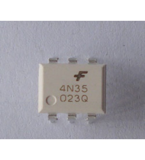
The 4N35 is a general-purpose optocoupler that consists of an infrared LED and a silicon phototransistor. It is designed to provide electrical isolation between input and output circuits while allowing signal transmission. This optocoupler is widely used in applications requiring noise isolation, signal isolation, and interface compatibility between high voltage and low voltage systems.
Key Features:
- High isolation voltage (typically 5,000 Vrms)
- Fast switching speed
- Low input current requirements
- Wide operating temperature range
- Compact and reliable design
- Compatible with various digital and analog circuits
Technical Specifications:
- Isolation Voltage: 5,000 Vrms (min)
- Input LED Forward Voltage: 1.2V (typ), 1.5V (max)
- Input LED Forward Current: 10mA (typ), 60mA (max)
- Collector-Emitter Voltage (VCEO): 30V (max)
- Collector Current (IC): 50mA (max)
- Current Transfer Ratio (CTR): 20% to 300% (at IF = 10mA, VCE = 5V)
- Rise Time (tr): 3µs (typ)
- Fall Time (tf): 2µs (typ)
- Package Type: 6-pin DIP
- Operating Temperature Range: -55°C to +100°C
Applications:
- Signal isolation in communication systems
- Switching power supplies
- Microcontroller interface isolation
- Motor control circuits
- Industrial automation systems
- Data acquisition systems
Usage:
- Circuit Design:
- Connect the anode of the input LED to the control signal source and the cathode to the ground, through a current-limiting resistor.
- Connect the collector of the phototransistor to the load or the microcontroller input, and the emitter to the ground.
- Current Limiting:
- Calculate and use an appropriate current-limiting resistor for the LED input to ensure it operates within the specified current range.
- Isolation:
- Ensure that the input and output sides of the optocoupler are properly isolated to prevent electrical interference and maintain safety.
- Testing:
- Verify the functionality of the optocoupler by applying a control signal to the LED input and observing the output response.
Caution:
- Handle the optocoupler with care to avoid damage from electrostatic discharge (ESD).
- Verify the electrical ratings and ensure the device operates within specified limits to avoid damage.
- Keep the input and output circuits isolated to maintain the integrity of the isolation barrier.
Datasheet:
For detailed technical specifications, refer to the 4N35 Datasheet.
In stock

