|
Description |
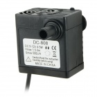
The 12V Mini Waterproof Pump is a compact, high-efficiency pump designed for a variety of applications requiring water movement or transfer. It is waterproof, allowing it to be used in submerged or wet environments. Its small size and robust performance make it ideal for use in aquariums, small fountains, cooling systems, and portable water systems.
Key Features:
- Compact and space-efficient
- Waterproof and suitable for submersible use
- High flow rate with low power consumption
- Durable construction with long service life
- Quiet operation
Technical Specifications:
- Operating Voltage: 12V DC
- Flow Rate: 180-250 liters per hour (L/h)
- Maximum Head (Lift): 1.5m to 2m
- Power Consumption: 4-6W
- Operating Temperature Range: 0°C to +60°C
- Dimensions: 60mm x 40mm x 40mm (length x width x height, approximate)
- Weight: 90g
- Inlet/Outlet Size: 6mm (barbed connectors)
- Material: Plastic body, rubber seals
Applications:
- Aquariums: Ideal for water circulation and filtration.
- Fountains: Suitable for small decorative water features and fountains.
- Portable Water Systems: Useful in camping, boating, and portable water transfer applications.
- Hydroponics: Employed in hydroponic systems for circulating nutrient solutions.
- Cooling Systems: Applied in small electronic cooling and machinery cooling systems.
Datasheet:
For detailed technical information, refer to the 12V Mini Waterproof Pump Datasheet provided by the manufacturer.
|
Description:
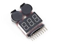
The 1-8S LiPo battery voltage detector with buzzer is an essential tool for monitoring and ensuring the safe operation of lithium polymer (LiPo) batteries used in RC models, drones, and other electronic devices. It provides real-time voltage detection for 1 to 8 series LiPo batteries, alerting users to low voltage conditions with an audible buzzer alarm. This compact device helps prevent over-discharge, which can damage batteries and reduce their lifespan, ensuring optimal performance and safety during use.
Key Features:
- Compatible Battery Types: 1-8S LiPo/Li-ion/LiMn/LiFe
- Voltage Detection Range: 2.7V to 25.2V (1S to 8S)
- Audible Buzzer Alarm: Alerts when voltage drops below preset levels
- Compact and Lightweight: Easy to carry and use in the field
- LED Indicators: Display battery voltage status for quick reference
- Reverse Polarity Protection: Prevents damage due to incorrect battery connection
Technical Specifications:
- Input Voltage: DC 5-27V (powered by the battery being tested)
- Accuracy: ±0.01V
- Operating Temperature: 0°C to 40°C
- Dimensions: Compact and portable design
- Weight: Lightweight for easy handling
Applications:
- RC Models (Cars, Planes, Boats)
- Drones and UAVs (Unmanned Aerial Vehicles)
- Portable Electronic Devices
- Battery Maintenance and Monitoring
|
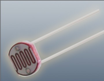
The Photoresistor LDR (Light Dependent Resistor) is a variable resistor whose resistance changes with the light intensity that falls upon it. It is widely used in light sensing applications and projects where detecting light levels is essential. LDRs are cost-effective, easy to use, and suitable for various electronic projects, including light meters, street lights, and other light-sensitive devices.
Key Features:
- Light Sensitivity: Resistance decreases with increasing light intensity
- Simple Interface: Easy to integrate with microcontrollers and analog circuits
- Low Cost: Economical solution for light detection
- Wide Range of Light Detection: Can detect various light levels from low to high intensity
- Compact Size: Fits easily into small projects
Technical Specifications:
- Resistance in Darkness: Typically 1MΩ (depending on specific model)
- Resistance in Bright Light: Typically 10-20kΩ (depending on specific model)
- Spectral Peak: Approximately 540nm (most sensitive to green light)
- Response Time: Rise time ~20ms, fall time ~30ms
- Operating Temperature Range: -30°C to +70°C
- Diameter: Typically 5mm to 10mm (depending on specific model)
Applications:
- Light Meters: Measure light intensity for photography and scientific applications.
- Street Lights: Automatic on/off control based on ambient light levels.
- Alarm Systems: Detect changes in light levels for security purposes.
- Consumer Electronics: Light-sensitive control in devices like clocks and displays.
- Educational Projects: Common component in learning modules for electronics.
Usage:
- Circuit Integration: Connect the LDR in a voltage divider circuit with a fixed resistor to create a variable voltage output based on light intensity.
- Microcontroller Interface: Read the voltage output from the LDR circuit using an analog input pin on a microcontroller.
- Programming: Write code to interpret the analog signal and perform actions based on light levels (e.g., turning on an LED when it gets dark).
- Testing: Calibrate the LDR circuit for the desired light sensitivity by adjusting the fixed resistor value.
Caution:
- Environment: Avoid exposure to extreme temperatures and humidity, which may affect the LDR’s performance.
- Handling: Handle with care to avoid damaging the sensitive surface of the LDR.
Datasheet:
For detailed technical specifications, refer to the Photoresistor LDR Datasheet.
|
Description:
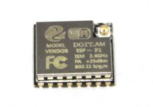
The ESP8266 ESP-F1 WiFi Module is a compact and highly integrated module designed for wireless communication applications. It features the ESP8266 chip, which provides WiFi connectivity and supports various network protocols. This module is suitable for embedding into electronic projects to enable wireless data transmission and reception.
Key Features:
- ESP8266 Chip: Provides reliable WiFi connectivity with support for various network protocols.
- Integrated Antenna: Simplifies design and reduces the need for external components.
- Compact Form Factor: Suitable for space-constrained applications.
- Built-in Flash Memory: For storing firmware and application code.
- Multiple Operating Modes: Supports station mode, access point mode, and station+access point mode.
- Low Power Consumption: Efficient power usage for battery-operated applications.
Technical Specifications:
- Chip: ESP8266
- Frequency Range: 2.4 GHz ISM band
- WiFi Standard: 802.11 b/g/n
- Flash Memory: Typically 512 KB to 4 MB (check specific module for exact memory)
- Operating Voltage: 3.3V DC
- Operating Current: Low power consumption (varies with operating mode)
- Interface: UART (serial communication), GPIO
- Dimensions: Compact size for easy integration (refer to datasheet for exact dimensions)
- Weight: Lightweight for minimal impact on overall project design
Applications:
- IoT Devices: Connects devices to the internet for smart home applications.
- Wireless Data Transmission: Enables wireless communication between devices.
- Embedded Systems: Integrates with microcontrollers for added WiFi functionality.
- Prototyping: Useful for developing and testing wireless applications.
Datasheet:
For detailed technical information and specifications, please refer to the ESP8266 ESP-F1 WiFi Module Datasheet.
|
|
The L7824 is a three-terminal positive voltage regulator that provides a fixed output of +24V. Designed for reliable and efficient voltage regulation, it is suitable for powering a range of electronic circuits and devices from a higher input voltage source. This regulator can supply up to 1.5A of current and includes built-in protection features to safeguard against thermal overload and short circuits.
Key Features:
- Fixed positive output voltage of +24V
- Capable of delivering up to 1.5A of current
- High voltage regulation with minimal dropout
- Built-in thermal overload and short-circuit protection
- Easy to use with minimal external components
- Ideal for applications requiring a stable +24V power supply
Technical Specifications:
- Output Voltage: +24V
- Maximum Output Current: 1.5A
- Input Voltage Range: Up to +35V
- Dropout Voltage: 2V (typical)
- Line Regulation: 0.01% (typical)
- Load Regulation: 0.1% (typical)
- Package Type: TO-220, D2PAK
Applications:
- Positive voltage power supplies
- Voltage regulation in electronic circuits
- Power management in devices requiring +24V
- Replacement for higher voltage linear power supplies
Usage:
- Connect the positive input voltage to the input terminal (IN).
- Connect the output terminal (OUT) to the load or circuit requiring +24V.
- Ensure the ground terminal (GND) is connected to the system ground.
- Use a heatsink if necessary to handle thermal dissipation, especially under high load conditions.
Caution:
- Do not exceed the maximum input voltage rating.
- Ensure proper heat dissipation to prevent overheating.
- Verify correct polarity to avoid damage to the regulator and connected components.
Datasheet:
For detailed technical specifications, refer to the L7824 Datasheet.
|
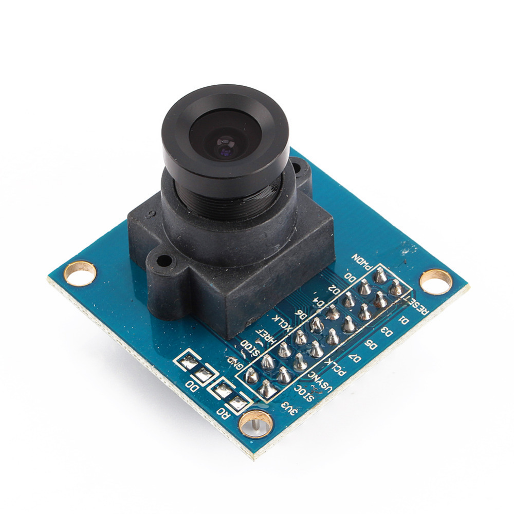
The OV7670 Camera Module is a low-cost camera module designed for use with Arduino and other microcontroller platforms. It features the OV7670 image sensor, which provides basic image capture capabilities suitable for low-resolution and hobbyist applications. This module is ideal for educational projects, DIY electronics, and simple image processing tasks.
Key Features:
- VGA (640×480) resolution capability
- Low power consumption
- Small form factor, easy to integrate with Arduino
- Includes an integrated image sensor (OV7670)
- Supports various output formats, including RGB565 and YUV422
- Built-in FIFO buffer to store image data temporarily
Technical Specifications:
- Image Sensor: OV7670 CMOS
- Resolution: VGA (640×480 pixels)
- Output Formats: RGB565, YUV422
- Power Supply: 3.3V DC (requires voltage regulator for Arduino 5V supply)
- Interface: 8-bit parallel data bus
- Operating Temperature Range: -20°C to +70°C
- Frame Rate: Up to 30 frames per second (fps) at VGA resolution
- Lens Type: Fixed-focus lens
Applications:
- Basic image capture and processing
- Educational and experimental projects involving image processing
- Low-resolution video streaming
- Simple security or surveillance systems
- Integration with Arduino for image-related applications
Usage:
- Connection: Connect the OV7670 module to the Arduino using the provided pin headers. Typically, connections include power (3.3V), ground, and data lines.
- Configuration: Use Arduino libraries and example code to configure the camera module and capture images. The module usually requires initialization and setup via I2C or SPI.
- Processing: Retrieve image data from the module and process it using Arduino or other compatible microcontrollers.
- Integration: Integrate the camera module into your project to enable image capturing or video streaming functionality.
Caution:
- The OV7670 operates at 3.3V, so be careful not to apply 5V directly to the module to avoid damage.
- Properly handle and secure the module to avoid damage to the delicate components.
- Ensure correct wiring and connections according to the module’s datasheet to avoid communication issues.
Datasheet:
For detailed technical specifications, refer to the OV7670 Camera Module Datasheet.
|
The Joystick Shield V1 is an expansion board designed for Arduino and other compatible microcontroller platforms. It features a joystick, buttons, and connectors that enable easy interfacing for a variety of applications, including gaming, robotics, and interactive projects. The shield provides an intuitive and user-friendly interface for controlling movements and actions in your projects.
Key Features:
- Analog Joystick: Two-axis joystick for precise control of movement.
- Push Buttons: Includes multiple push buttons for additional input options.
- Shield Design: Easily stackable on top of Arduino boards, maintaining a compact form factor.
- Plug and Play: Simple to connect and start using with minimal setup required.
- Versatile Applications: Suitable for gaming controllers, robotic controls, and interactive systems.
Technical Specifications:
- Joystick: 2-axis (X and Y) analog joystick with a push-button function
- Buttons: 5 push buttons (up, down, left, right, select)
- Interface: Connects to Arduino through the standard shield interface
- Operating Voltage: 5V (supplied by the Arduino board)
- Dimensions: Compatible with standard Arduino board dimensions
Applications:
- Gaming Controllers: Create custom gaming controllers for various platforms.
- Robotics: Use the joystick and buttons to control robotic movements and actions.
- Interactive Projects: Develop interactive installations and projects that require user input.
- Prototyping: Ideal for quickly testing and prototyping control interfaces.
Datasheet:
For detailed technical specifications, refer to the Joystick Shield V1 Datasheet.
|
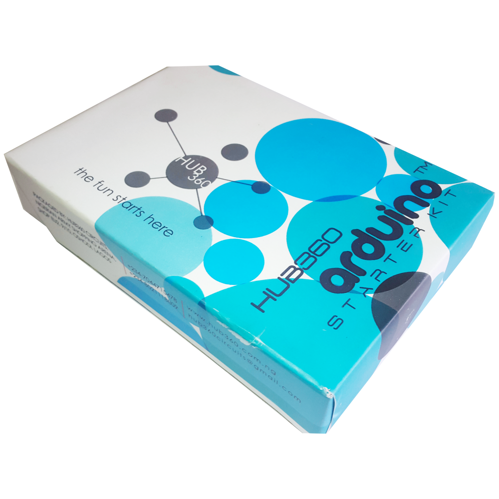
The Hub360 Arduino Starter Kit is a comprehensive package designed for beginners and enthusiasts looking to dive into the world of electronics and programming. This kit includes Arduino Uno, which is a microcontroller board based on the ATmega328P. The kit provides a variety of components and modules to help users learn and experiment with different electronic projects and concepts.
Key Features:
- Includes Arduino Uno board
- Comprehensive set of components and modules for various projects
- Ideal for beginners and hobbyists
- Detailed tutorial and project guide included
- USB interface for easy programming and power
- Compatible with Arduino IDE and various libraries
Technical Specifications:
- Microcontroller: ATmega328P
- Operating Voltage: 5V
- Input Voltage (recommended): 7-12V
- Digital I/O Pins: 14 (6 PWM outputs)
- Analog Input Pins: 6
- DC Current per I/O Pin: 20mA
- Flash Memory: 32KB (ATmega328P) of which 0.5KB used by bootloader
- SRAM: 2KB (ATmega328P)
- EEPROM: 1KB (ATmega328P)
- Clock Speed: 16 MHz
Kit Contents:
- ARDUINO BOARD 1
- ARDUINO USB CABLE 1
- ARDUINO BATTERY CONNECTOR 1
- 400 HOLE BREADBOARD 1
- LED (RED, YELLOW , GREEN, WHITE) 20
- RGB LED 1
- JUMPER WIRE(M-M, M-F, F-F) 120
- PHOTORESISTOR (LDR) 3
- MALE HEADERS 40
- ULTRASONIC SENSOR 1
- FLAME SENSOR 1
- TEMP./HUMIDITY SENSOR 1
- TILT SENSOR 1
- LASER SENSOR 1
- PIR MOTION SENSOR 1
- RESISTORS(220K, 1K, 10K,100K) 40
- 7 SEGMENT DISPLAY 1
- SG90 SERVO 1
- REMOTE CONTROL 1
- BUZZER 1
- 2N2222 2
- TSOP 1838 1
- RF TRANSMITTER 1
- RF RECEIVER 1
- TACT SWITCH 5
- 16*2 LCD DISPLAY
Applications:
- Learning basic electronics and programming
- Building interactive projects and prototypes
- Developing skills in microcontroller-based design
- Experimenting with sensors and actuators
- Creating DIY electronic devices
Usage:
- Setup:
- Connect the Arduino Uno board to your computer using the USB cable.
- Install the Arduino IDE and configure it to recognize the board.
- Programming:
- Write or upload sample code (sketches) to the Arduino board using the Arduino IDE.
- Utilize the provided components and modules to build and test different circuits.
- Experimentation:
- Follow the detailed tutorials and project guide to create various projects.
- Modify and expand on the sample projects to enhance learning and creativity.
Caution:
- Handle the components carefully to avoid damage.
- Ensure proper connections and polarity to prevent short circuits or component failure.
- Verify the code and circuit connections before powering the board.
Datasheet:
For detailed technical specifications of the Arduino Uno, refer to the Arduino Uno Datasheet.
|
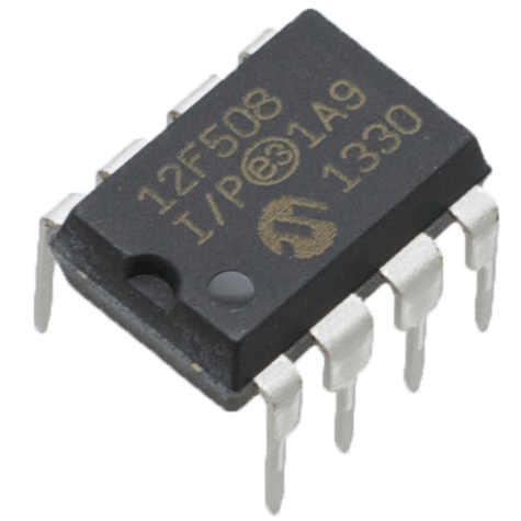
The PIC12F509 is an 8-bit microcontroller from Microchip’s PIC series, designed for low-power and compact applications. It features a minimalistic design with essential peripherals, making it ideal for simple control tasks in embedded systems where space and power efficiency are critical.
Key Features:
- 8-bit architecture
- 1KB Flash program memory
- 64 bytes SRAM data memory
- 64 bytes Electrically Erasable Programmable Read-Only Memory (EEPROM)
- 5 I/O pins
- 8-bit Timer0
- 8-bit Watchdog Timer (WDT)
- Low-power sleep mode
Technical Specifications:
- Operating Voltage: 2.0V to 5.5V
- Operating Frequency: Up to 8MHz
- Program Memory Size: 1KB (Flash)
- Data Memory Size: 64 bytes SRAM
- EEPROM Size: 64 bytes
- Number of I/O Pins: 5
- Timers: 8-bit Timer0
- Package Type: 8-pin DIP, 8-pin SOIC
Applications:
- Low-power sensors and controls
- Simple automation tasks
- Consumer electronics
- Battery-powered devices
- Basic monitoring and logging systems
Usage:
- Connect the microcontroller to a power supply within the operating voltage range.
- Program the microcontroller using its Flash program memory for specific application tasks.
- Utilize the 5 I/O pins for interfacing with external devices.
- Implement timing functions with the 8-bit Timer0 and manage low-power states with the sleep mode.
Caution:
- Ensure the microcontroller is powered within the specified voltage range to avoid damage.
- Adhere to maximum current ratings for I/O pins.
- Handle the microcontroller carefully to prevent static discharge damage.
Datasheet:
For detailed technical specifications, refer to the PIC12F509 Datasheet.
|
|
A small size dotted Vero board, also known as a stripboard or prototyping board, is a type of circuit board that is used for prototyping and building electronic circuits. It features a grid of holes with copper pads that allow components to be easily soldered onto the board. The dotted pattern provides flexibility in layout, making it ideal for custom circuit designs and small electronic projects.
Key Features:
- Dotted pattern for versatile circuit layout
- High-quality FR4 material for durability
- Copper pads for easy soldering
- Small size for compact projects
- Compatible with through-hole components
- Suitable for prototyping and custom circuit building
Technical Specifications:
- Material: FR4 (fiberglass epoxy laminate)
- Size: Typically around 70mm x 90mm (varies by manufacturer)
- Hole Pitch: 2.54mm (standard 0.1 inch grid)
- Hole Diameter: 1.0mm (suitable for most through-hole components)
- Thickness: 1.6mm
- Copper Thickness: 35µm (1oz/ft²)
- Pattern: Dotted (individual copper pads)
- Number of Holes: Varies by board size (e.g., 25×35 grid for 70mm x 90mm board)
Applications:
- Prototyping electronic circuits
- Custom circuit design
- DIY electronics projects
- Educational and learning purposes
- Small-scale production of custom circuits
Usage:
- Design the Circuit:
- Plan the layout of your components and connections on the Vero board.
- Place the Components:
- Insert the components into the holes according to your circuit design.
- Solder the Components:
- Solder the component leads to the copper pads on the reverse side of the board.
- Create Connections:
- Use solder bridges or wire links to create electrical connections between the copper pads as needed.
- Test the Circuit:
- Verify the circuit functionality and make any necessary adjustments or corrections.
Caution:
- Ensure proper soldering techniques to avoid short circuits or poor connections.
- Handle the board carefully to avoid damaging the copper pads or FR4 material.
- Verify the component placement and connections before powering the circuit.
|
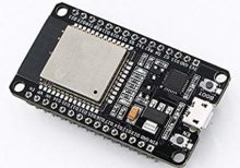
The ESP32 Development Board is a powerful and versatile microcontroller board designed for IoT (Internet of Things) and embedded applications. Based on the ESP32 microcontroller by Espressif Systems, it features integrated Wi-Fi and Bluetooth capabilities, making it ideal for a wide range of wireless communication projects. The ESP32 Development Board is suitable for both beginners and experienced developers due to its rich feature set and extensive community support.
Key Features:
- Microcontroller: ESP32
- Wireless Connectivity: Integrated Wi-Fi (802.11 b/g/n) and Bluetooth (v4.2 BR/EDR and BLE)
- CPU: Dual-core Tensilica LX6 processor
- Operating Voltage: 3.3V
- Flash Memory: 4 MB (varies by model)
- SRAM: 520 KB
- GPIO Pins: 36 (varies by model)
- Interfaces: UART, SPI, I2C, I2S, PWM, ADC, DAC
- Power Management: Ultra-low power management modes
- Integrated Sensors: Hall sensor, temperature sensor
Technical Specifications:
- Microcontroller: ESP32-D0WDQ6 or ESP32-D0WD
- Clock Speed: Up to 240 MHz
- Flash Memory: 4 MB (varies by model)
- SRAM: 520 KB
- GPIO Pins: 36 (varies by model)
- Analog Inputs: 18 channels of 12-bit SAR ADCs
- Digital-to-Analog Converter (DAC): 2 channels of 8-bit DACs
- PWM Channels: 16
- UART: 3
- SPI: 4
- I2C: 2
- I2S: 2
- Dimensions: Typically around 50 mm x 25 mm (varies by model)
Applications:
- IoT Projects: Ideal for home automation, smart sensors, and connected devices.
- Wearables: Suitable for developing wearable devices with wireless connectivity.
- Prototyping: Excellent for rapid prototyping of electronic projects.
- Embedded Systems: Useful in creating embedded systems with advanced capabilities.
- Robotics: Can be used in robotics for communication and control tasks.
- Education: Great for teaching electronics and programming concepts.
Datasheet:
For detailed technical information, refer to the ESP32 Development Board Datasheet provided by Espressif Systems or the specific board manufacturer.
|
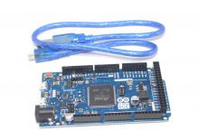
Description: The Arduino Due R3 is a powerful 32-bit microcontroller board based on the ARM Cortex-M3 processor. It offers enhanced performance and greater capabilities compared to earlier Arduino boards, making it ideal for complex projects that require advanced computing power and high-speed processing. The board features a large number of digital and analog I/O pins, along with built-in peripherals and communication interfaces, providing flexibility for a wide range of applications.
Key Features:
- Based on the 32-bit ARM Cortex-M3 processor
- 54 digital I/O pins, 12 analog inputs, and 4 UARTs
- 84 MHz clock speed for high-speed operation
- 512 KB Flash memory and 96 KB SRAM
- USB OTG (On-The-Go) and Native USB support
- Compatible with the Arduino IDE for easy programming
Technical Specifications:
- Microcontroller: Atmel SAM3X8E (ARM Cortex-M3)
- Operating Voltage: 3.3V
- Input Voltage: 7V to 12V
- Digital I/O Pins: 54
- Analog Inputs: 12
- Flash Memory: 512 KB
- SRAM: 96 KB
- Clock Speed: 84 MHz
- USB Interfaces: USB OTG, Native USB
- Dimensions: 101.6 mm x 53.3 mm
Applications:
- Advanced robotics
- Complex sensor integration
- High-speed data processing
- Industrial control systems
- DIY electronics projects requiring high processing power
Datasheet: For detailed technical information, refer to the Arduino Due R3 32-bit ARM Board Datasheet.
|
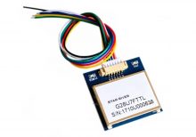
The VK2828 G28U7FTTL is a high-performance GPS module designed for aviation and other high-precision applications. It features a wide range of operational frequencies and is capable of delivering accurate positional data for navigation and tracking purposes. The module is ideal for integration into systems requiring reliable and precise GPS information.
Key Features:
- High Update Rate: Capable of updating position data from 1Hz to 10Hz, allowing for smooth and accurate tracking
- Sensitivity: Designed for use in aviation, providing robust performance in various environmental conditions
- Compatibility: Supports standard GPS protocols for easy integration into existing systems
- Compact Size: Suitable for integration into space-constrained applications
Technical Specifications:
- Type: GPS Module
- Model: VK2828 G28U7FTTL
- Update Rate: 1Hz to 10Hz
- Frequency Range: Supports standard GPS frequencies
- Sensitivity: High sensitivity for accurate positioning
- Protocol: NMEA-0183
- Operating Voltage: Typically 3.3V to 5V DC
- Power Consumption: Low power consumption for battery-operated applications
- Dimensions: Varies by model, generally compact for easy integration
- Antenna: May include an external or integrated antenna depending on the model
Applications:
- Aviation: Navigation and tracking for aircraft
- Marine: Boat and ship navigation
- Automotive: Advanced driver-assistance systems (ADAS)
- Outdoor Activities: Hiking and sports tracking
- Industrial: Asset tracking and fleet management
Usage:
- Powering the Module: Connect the GPS module to a suitable power source within the specified voltage range.
- Connecting the Antenna: Ensure the antenna is properly connected and positioned for optimal signal reception.
- Data Integration: Use the NMEA protocol to receive GPS data, including latitude, longitude, altitude, and time.
- Integration: Connect the GPS module to your system or application for real-time tracking and navigation.
Caution:
- Signal Reception: Ensure the module has a clear view of the sky for optimal GPS signal reception.
- Voltage: Verify the operating voltage to avoid damage to the module.
- Antenna Placement: Position the antenna to minimize interference and maximize signal strength.
Datasheet:
For detailed technical specifications, refer to the VK2828 G28U7FTTL Datasheet .
|
|
The Arduino USB Host Shield enables the connection of USB devices to an Arduino board, expanding its functionality by allowing it to interface with USB peripherals. Based on the MAX3421E USB controller, this shield supports full-speed USB operation and is compliant with USB specification 2.0. It is ideal for projects that require interaction with USB devices such as keyboards, mice, or storage devices.
Key Features:
- Connects USB devices to Arduino boards
- Based on the MAX3421E USB controller (datasheet)
- Supports full-speed USB operation
- Compatible with a variety of USB peripherals
Technical Specifications:
- Operating Voltage: 5V
- USB Controller: MAX3421E
- Maximum Current: 500mA (when Arduino is powered by an external power supply)
- Maximum Current: 400mA (when Arduino is powered via USB)
Applications:
- Connecting USB devices (keyboards, mice) to Arduino
- USB data logging and communication
- Building USB-controlled projects
Usage:
- Mount the USB Host Shield on the Arduino board.
- Connect the USB device to the shield’s USB port.
- Use the Arduino USB Host library to interface with the USB device.
- Develop and upload the necessary Arduino sketch for device interaction.
Caution:
- Ensure that the Arduino power source is sufficient to provide the required current for connected USB devices.
- Verify compatibility of connected USB devices with the shield.
- Follow manufacturer guidelines for proper installation and use.
Datasheet:
For detailed technical specifications, refer to the MAX3421E Datasheet.
|
Description:
The W78E052DDG is an enhanced 8-bit microcontroller with a rich instruction set, featuring a 12-clock architecture. This microcontroller is designed for high-performance applications, offering increased processing speed and improved peripheral capabilities compared to standard 8051 devices. It is widely used in industrial control, consumer electronics, and embedded system applications.
Key Features:
- Fully compatible with the standard 8052 microcontroller
- 8-bit CPU optimized for performance
- 64KB Flash EPROM for program storage
- 256 bytes of on-chip RAM
- 4KB of auxiliary RAM
- Supports up to 32 general-purpose I/O pins
- Two 16-bit timers/counters
- One watchdog timer
- On-chip oscillator and clock circuitry
- Enhanced UART for serial communication
- Interrupt capability with 6 interrupt sources and 2 levels of priority
- Dual DPTR for data transfer
Technical Specifications:
- Package Type: PLCC-44, PQFP-44
- Supply Voltage: 4.5V to 5.5V
- Operating Frequency: Up to 40MHz
- Operating Temperature Range: -40°C to +85°C
- Power Consumption: Low power modes for energy efficiency
- Programming: Supports In-System Programming (ISP)
Applications:
- Industrial Automation
- Consumer Electronics
- Embedded Control Systems
- Automotive Electronics
- Communication Devices
- Home Appliances
Datasheet:
For detailed technical information, refer to the W78E052DDG Datasheet.
|
The BK-AVR128 ATMEGA128 AVR Development Board is a comprehensive and versatile platform designed for developing and prototyping with the ATmega128 microcontroller. It provides all the necessary components and interfaces to facilitate easy and efficient development, making it ideal for both beginners and experienced developers in embedded systems.
Key Features:
- Microcontroller: Includes the ATmega128 AVR microcontroller with 128KB of Flash memory, 4KB of SRAM, and 4KB of EEPROM.
- Comprehensive I/O: Multiple digital and analog I/O pins, including USART, SPI, I2C, and ADC channels.
- External Memory Interface: Supports external SRAM/Flash for expanded memory needs.
- Onboard Peripherals: Includes LEDs, push buttons, and a reset switch for quick testing and prototyping.
- Power Options: Can be powered via USB or an external power supply (7V-12V).
- ISP Programming: Integrated In-System Programming (ISP) header for easy firmware uploads.
- Breadboard-Compatible: Designed to be easily integrated with standard breadboards and other prototyping tools.
Technical Specifications:
- Microcontroller: ATmega128
- Clock Speed: 16MHz
- Flash Memory: 128KB
- SRAM: 4KB
- EEPROM: 4KB
- Digital I/O Pins: 53
- Analog Input Pins: 8
- PWM Channels: 8
- Communication Interfaces: USART, SPI, I2C
- Operating Voltage: 5V
- Power Supply: USB or external 7V-12V
- Dimensions: 80mm x 50mm (approx.)
Applications:
- Embedded System Development: Ideal for developing and prototyping embedded applications.
- Educational Projects: Perfect for learning AVR microcontroller programming and interfacing.
- Robotics: Suitable for developing control systems for robots and automation projects.
- IoT Projects: Can be used as a central controller in various Internet of Things (IoT) applications.
- Custom Electronics: Versatile platform for creating custom electronic devices and systems.
|
Description:
The Mega 2560 PRO with CH340 is a compact and powerful development board based on the ATmega2560 microcontroller. Designed for advanced applications, it offers extensive I/O capabilities, high processing power, and reliable USB communication via the CH340 chip. This board is ideal for projects requiring multiple interfaces, large memory, and robust performance.
Key Features:
- Microcontroller: ATmega2560 with 54 digital I/O pins, 16 analog inputs, and 4 UARTs.
- USB to Serial Communication: CH340 chip for reliable USB communication.
- Compact Design: Smaller form factor compared to standard Mega 2560 boards.
- High Memory Capacity: 256 KB Flash memory, 8 KB SRAM, and 4 KB EEPROM.
- Multiple Interfaces: I2C, SPI, and serial interfaces for versatile connectivity.
- Wide Operating Voltage Range: Supports 7-12V DC input voltage.
Technical Specifications:
- Microcontroller: ATmega2560
- Operating Voltage: 5V
- Input Voltage (recommended): 7-12V
- Digital I/O Pins: 54 (of which 15 provide PWM output)
- Analog Input Pins: 16
- DC Current per I/O Pin: 20 mA
- Flash Memory: 256 KB (8 KB used by bootloader)
- SRAM: 8 KB
- EEPROM: 4 KB
- Clock Speed: 16 MHz
- USB Controller: CH340
- Dimensions: Compact size for integration into various projects
Applications:
- Robotics: Ideal for controlling multiple motors, sensors, and other peripherals.
- Embedded Systems: Suitable for complex embedded system designs.
- IoT Projects: Can be used in Internet of Things (IoT) applications requiring extensive I/O and memory.
- Automation: Perfect for automation projects needing high processing power and multiple interfaces.
- Prototyping: Great for prototyping advanced electronics and software applications.
Datasheet:
For detailed technical information and specifications, please refer to the Mega 2560 PRO with CH340 Datasheet.
|
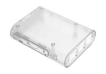
The Raspberry Pi 3 Transparent Injection Case is a protective enclosure designed for the Raspberry Pi 3 Model B and Model B+. It provides a clear, durable case that allows easy viewing of the Raspberry Pi while protecting it from dust, damage, and physical impact. The case is made from high-quality injection-molded plastic, ensuring a precise fit and a sleek, modern look.
Key Features:
- Transparent design for visibility of the Raspberry Pi board
- Injection-molded plastic construction for durability
- Precise cutouts for all ports, connectors, and GPIO pins
- Easy access to SD card slot and USB ports
- Ventilation slots for effective heat dissipation
- Simple snap-together assembly; no tools required
- Includes mounting hardware and rubber feet for stability
Technical Specifications:
- Material: Transparent injection-molded plastic
- Compatibility: Raspberry Pi 3 Model B and Model B+
- Color: Clear/Transparent
- Dimensions: Varies slightly by manufacturer (typically around 90mm x 60mm x 30mm)
- Weight: Varies slightly by manufacturer (typically around 50g)
Applications:
- Protecting Raspberry Pi 3 during use and handling
- Displaying the Raspberry Pi while maintaining access to ports
- Enclosing Raspberry Pi in a professional or educational setting
- Enhancing the aesthetics of Raspberry Pi-based projects
Usage:
- Place the Raspberry Pi 3 into the case, aligning it with the cutouts and mounting points.
- Snap the case parts together to secure the Raspberry Pi in place.
- Ensure all ports and connectors are accessible through the case openings.
- Mount the case using the included rubber feet or screws if required.
Caution:
- Handle the case carefully to avoid scratches or cracks.
- Ensure proper ventilation to prevent overheating of the Raspberry Pi.
- Verify that all connectors and ports are aligned and accessible before use.
Datasheet:
For detailed technical specifications, refer to the Raspberry Pi 3 Transparent Injection Case database.
|
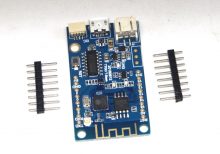
Description: The TTGO T-BASE ESP8266 WiFi Module is a compact and versatile development board based on the ESP8266 microcontroller. It integrates WiFi connectivity and is designed for IoT (Internet of Things) applications, allowing devices to connect to wireless networks and communicate over the internet. The board features various interfaces and GPIO pins, making it suitable for a wide range of projects requiring WiFi connectivity and microcontroller capabilities.
Key Features:
- ESP8266 microcontroller with integrated WiFi connectivity
- Onboard antenna for wireless communication
- GPIO pins and interfaces for peripheral connections
- Integrated USB-to-serial converter for programming and debugging
- Compact size suitable for embedded applications
- Low power consumption
- Support for Arduino IDE and NodeMCU firmware
- Built-in micro-USB port for power and programming
Technical Specifications:
- Microcontroller: ESP8266
- Operating Voltage: 3.3V (regulated)
- WiFi Standard: 802.11 b/g/n
- Interfaces: GPIO, I2C, SPI, UART, ADC
- Programming: Arduino IDE, NodeMCU firmware
- Dimensions: Compact size suitable for integration into various projects
- Weight: Lightweight for portable and embedded applications
Applications:
- IoT (Internet of Things) devices and projects
- Home automation and smart devices
- Wireless sensor networks
- Remote monitoring and control systems
- Embedded WiFi applications
- Educational and prototyping projects
Datasheet: For detailed technical information, refer to the ESP8266 WiFi Module Datasheet.
|
Description:
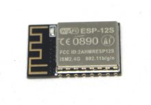
The ESP8266 ESP-12S WiFi Module is a versatile and widely used module for adding WiFi connectivity to various electronic projects. Based on the ESP8266 chip, this module offers a comprehensive range of features for wireless communication and is ideal for Internet of Things (IoT) applications.
Key Features:
- ESP8266 Chip: Provides robust WiFi connectivity with support for various networking protocols.
- Integrated PCB Antenna: Built-in antenna design for reliable wireless performance.
- Compact and Easy to Integrate: Designed to fit easily into small and compact spaces.
- Multiple Operating Modes: Supports Station mode, Access Point mode, and Station + Access Point mode.
- Rich I/O Options: Includes GPIO, UART, and other interfaces for versatile applications.
- Low Power Consumption: Suitable for battery-powered and energy-efficient projects.
Technical Specifications:
- Chip: ESP8266
- Frequency Range: 2.4 GHz ISM band
- WiFi Standard: 802.11 b/g/n
- Flash Memory: Typically 4 MB
- Operating Voltage: 3.3V DC
- Operating Current: Low power consumption (varies with operating mode)
- Interface: UART (serial communication), GPIO
- Dimensions: 24.8 mm x 16.6 mm x 2.8 mm
- Weight: Lightweight for easy integration into various designs
Applications:
- IoT Devices: Enables WiFi connectivity for smart home and industrial applications.
- Wireless Communication: Facilitates wireless data transmission between devices.
- Embedded Systems: Adds WiFi functionality to microcontroller-based projects.
- Prototyping and Development: Ideal for developing and testing wireless applications.
Datasheet:
For detailed technical information and specifications, please refer to the ESP8266 ESP-12S WiFi Module Datasheet.
|
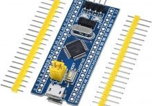
Description:
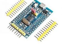
The STM32F030F4P6 Cortex-M0 development board is a versatile microcontroller board based on the STM32F030F4P6 microcontroller from STMicroelectronics. It is designed to provide a cost-effective platform for developing and prototyping embedded systems and IoT applications. The board features a compact form factor with integrated components, including GPIO pins, UART, SPI, I2C interfaces, and analog inputs, suitable for a wide range of applications requiring low-power operation and real-time processing capabilities.
Key Features:
- Microcontroller: STM32F030F4P6 ARM Cortex-M0 CPU
- Operating Voltage: 2.0V to 3.6V
- Clock Speed: Up to 48 MHz
- Flash Memory: 16 KB
- SRAM: 4 KB
- EEPROM: 1 KB
- Digital I/O Pins: GPIO pins with interrupt capability
- Analog Input Pins: ADC channels
- Communication Interfaces: UART, SPI, I2C
- USB Interface for programming and power
- Integrated LED indicators and reset button
Technical Specifications:
- Dimensions: Compact and varies by model
- Power Supply: USB or external power source (5V)
- On-board Debugger/Programmer: STM32 microcontroller in-circuit debugger/programmer
- Development Software: Compatible with STM32CubeIDE, Keil, and other ARM development tools
- Operating Temperature Range: -40°C to +85°C
- Integrated Development Environment (IDE): Supports C/C++ programming with libraries and examples
Applications:
- Embedded Systems Development
- IoT (Internet of Things) Devices
- Sensor Interfaces and Data Acquisition Systems
- Motor Control and Power Management
- Industrial Automation
- Consumer Electronics
Datasheet:
For detailed technical information, refer to the STM32F030F4P6 Datasheet.
|
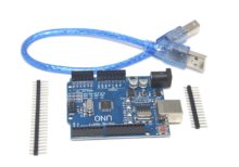
- The Arduino UNO R3 SMD is a popular and versatile microcontroller board based on the ATmega328P microcontroller. The SMD (Surface-Mount Device) version features the ATmega328P microcontroller in an SMD package, offering the same functionality as the traditional UNO R3 but with a more compact design. It is widely used for a variety of projects, from simple experiments to complex prototypes.
Key Features:
- Microcontroller: ATmega328P in SMD package
- Operating Voltage: 5V
- Input Voltage (recommended): 7-12V
- Digital I/O Pins: 14 (of which 6 provide PWM output)
- Analog Input Pins: 6
- Flash Memory: 32 KB (ATmega328P) of which 0.5 KB used by bootloader
- SRAM: 2 KB (ATmega328P)
- EEPROM: 1 KB (ATmega328P)
- Clock Speed: 16 MHz
- USB Connection: Standard USB-B for programming and communication
- Power Jack: 2.1mm center-positive barrel jack
- ICSP Header: For in-circuit programming
- Reset Button: For easy reset of the microcontroller
Technical Specifications:
- Microcontroller: ATmega328P
- Operating Voltage: 5V
- Input Voltage (limits): 6-20V
- Digital I/O Pins: 14 (6 PWM)
- PWM Digital I/O Pins: 6
- Analog Input Pins: 6
- DC Current per I/O Pin: 20 mA
- DC Current for 3.3V Pin: 50 mA
- Flash Memory: 32 KB (ATmega328P) of which 0.5 KB used by bootloader
- SRAM: 2 KB (ATmega328P)
- EEPROM: 1 KB (ATmega328P)
- Clock Speed: 16 MHz
- Length: 68.6 mm
- Width: 53.4 mm
- Weight: 25 g
Applications:
- Educational Projects: Ideal for beginners and students learning electronics and programming.
- Prototyping: Widely used for developing and testing new electronic devices and systems.
- Robotics: Can be used as a controller for various robotics projects.
- Home Automation: Suitable for creating smart home devices and automation systems.
- DIY Projects: Perfect for hobbyists and makers building custom gadgets and interactive installations.
Datasheet:
For detailed technical specifications, refer to the Arduino UNO R3 SMD Datasheet.
|
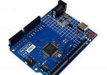
The Arduino Uno R4 Minima is a versatile microcontroller board based on the Renesas RA4M1 32-bit microcontroller. It is the latest addition to the popular Arduino Uno family, designed for both beginners and experienced developers. The R4 Minima offers enhanced performance, increased memory, and additional features while maintaining compatibility with existing Arduino shields and software.
Key Features:
- 32-bit ARM Cortex-M4 core (Renesas RA4M1)
- 256KB Flash memory for program storage
- 32KB SRAM for data storage
- USB Type-C connector for power and programming
- Improved processing speed and efficiency
- Onboard LED indicators
- Compatible with Arduino IDE and existing shields
- Enhanced security features
Technical Specifications:
- Microcontroller: Renesas RA4M1 (32-bit ARM Cortex-M4)
- Operating Voltage: 3.3V
- Input Voltage (recommended): 7-12V
- Input Voltage (limits): 6-20V
- Digital I/O Pins: 14 (6 PWM output)
- Analog Input Pins: 6
- Flash Memory: 256KB
- SRAM: 32KB
- Clock Speed: 48 MHz
- USB Connector: USB Type-C
- LED Indicators: Power, TX, RX, and user LED
- Dimensions: 68.6mm x 53.4mm
- Weight: Approximately 25g
Applications:
- Prototyping and development
- Educational projects
- DIY electronics
- Robotics
- IoT devices
- Automation systems
Usage:
- Programming:
- Connect the Arduino Uno R4 Minima to your computer using a USB Type-C cable.
- Open the Arduino IDE and select “Arduino Uno R4 Minima” from the board menu.
- Write your code and upload it to the board.
- Powering:
- The board can be powered via the USB Type-C connector or an external power supply.
- Ensure the input voltage is within the recommended range (7-12V).
- Connecting Peripherals:
- Use the digital and analog I/O pins to connect sensors, actuators, and other peripherals.
- Utilize existing Arduino shields for extended functionality.
Caution:
- Avoid exposing the board to moisture or extreme temperatures.
- Handle the board with care to prevent damage from electrostatic discharge (ESD).
- Ensure proper voltage levels to avoid damaging the microcontroller.
Datasheet:
For detailed technical specifications, refer to the Arduino Uno R4 Minima Datasheet.
|
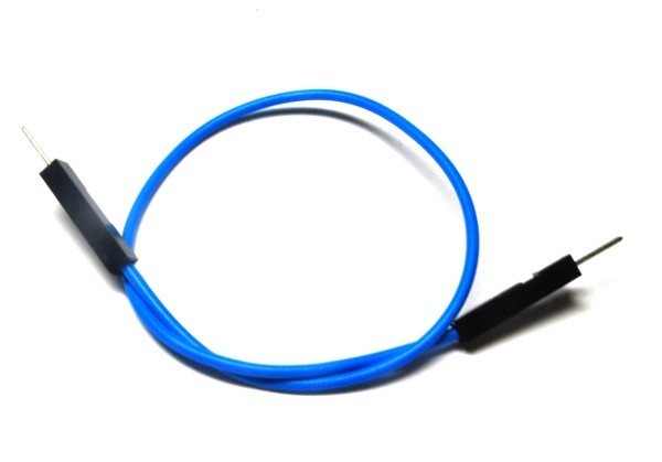
A single male-male jumper wire features male connectors on both ends and is used for making connections between components, breadboards, and other circuit boards. These wires are essential in prototyping and development for creating temporary circuits or testing designs. They allow for easy and flexible connections without the need for soldering.
Key Features:
- Connectors: Male connectors on both ends
- Wire Type: Flexible, insulated wire for easy handling and routing
- Length: Available in various lengths to suit different project needs
- Color-Coded: Available in multiple colors for easy identification and organization
- Durability: Made from high-quality materials for reliable and repeated use
- Compatibility: Suitable for standard 2.54mm (0.1 inch) pitch headers and connectors
Technical Specifications:
- Connector Type: Male-to-male
- Wire Gauge: Typically 28 AWG
- Insulation Material: PVC or similar flexible plastic
- Pitch: 2.54mm (0.1 inch)
- Length Options: Common lengths include 10cm, 20cm, 30cm, and others
- Operating Temperature: Typically -40°C to +80°C
- Current Rating: Usually up to 1A
Applications:
- Prototyping: Ideal for making connections on breadboards and development boards.
- Educational Projects: Used in educational settings to teach electronics and programming concepts.
- DIY Electronics: Suitable for hobbyists and makers working on various electronics projects and experiments.
- Temporary Connections: Useful for creating temporary connections during development and testing.
- Interfacing Components: Facilitates connections between components and modules with male pin headers.
|
The PIC12F675 is an 8-bit microcontroller from Microchip’s PIC12 family, known for its low-power operation and compact size. It is designed for applications requiring a small form factor and includes integrated peripherals like timers and an Analog-to-Digital Converter (ADC), making it suitable for simple control tasks and sensor interfacing.
Key Features:
- 8-bit microcontroller with 14-bit instruction set architecture
- 128 bytes of RAM
- 256 bytes of EEPROM
- 10-bit Analog-to-Digital Converter (ADC)
- Two Timer modules (Timer0 and Timer1)
- Watchdog Timer (WDT)
- Capture/Compare/PWM (CCP) module
- Low-power operation with multiple sleep modes
- 6-bit wide I/O ports
- Internal oscillator
Technical Specifications:
- Operating Voltage: 2.0V to 5.5V
- Operating Frequency: Up to 20MHz
- Program Memory Size: 1KB (Flash)
- Data Memory Size: 64 bytes SRAM
- EEPROM Size: 128 bytes
- Number of I/O Pins: 6
- Timers: 8-bit Timer0, 8-bit Timer1
- ADC Resolution: 10-bit
- Package Type: 8-pin PDIP, 8-pin SOIC
Applications:
- Consumer electronics
- Battery-operated devices
- Simple sensor interfacing
- LED and display control
- Remote controls
- Low-power embedded systems
Usage:
- Connect the microcontroller to a power supply within the recommended voltage range.
- Program the PIC12F675 using its Flash program memory for specific tasks.
- Utilize the ADC for analog signal processing and Timer modules for timing tasks.
- Manage power consumption effectively using sleep modes for battery-operated applications.
Caution:
- Check power supply and connections to prevent damage.
- Handle with care to avoid electrostatic discharge (ESD) damage.
- Ensure I/O pins do not exceed maximum current ratings to prevent damage.
Datasheet:
For detailed technical specifications, refer to the PIC12F675 Datasheet.
|
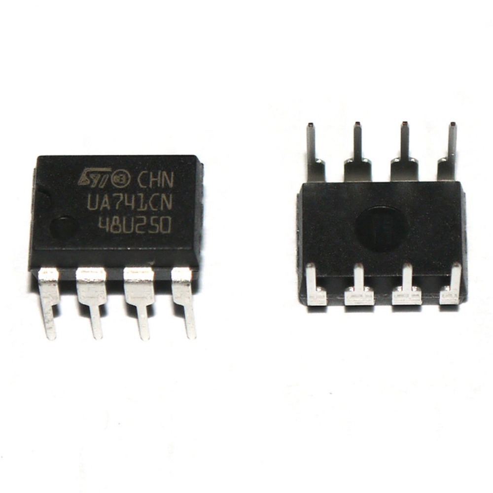
The UA741 is a general-purpose operational amplifier featuring offset-voltage null capability. The high-gain, internally frequency-compensated op-amp is designed to operate from a single or dual power supply over a wide range of voltages. It is an ideal choice for applications requiring low input bias current, low offset voltage, and high input impedance.
Key Features:
- Internally frequency compensated for unity gain
- Large signal voltage gain of 106 dB
- Wide power supply range: ±10V to ±15V
- Short-circuit protection
- Offset-voltage null capability
- Low input bias current: 80 nA (typical)
- High input impedance: 2 MΩ (typical)
- Low power consumption
- Compatible with standard LM741 pin configurations
Technical Specifications:
- Supply Voltage Range: ±10V to ±22V
- Input Offset Voltage: 1 mV (typical)
- Input Bias Current: 80 nA (typical)
- Input Impedance: 2 MΩ (typical)
- Output Impedance: 75Ω (typical)
- Large Signal Voltage Gain: 106 dB (typical)
- Unity-Gain Bandwidth: 1 MHz (typical)
- Slew Rate: 0.5 V/µs (typical)
- Common Mode Rejection Ratio (CMRR): 90 dB (typical)
- Power Supply Rejection Ratio (PSRR): 96 dB (typical)
- Operating Temperature Range: 0°C to +70°C
- Package Types: 8-pin PDIP, SOIC, TO-99
Applications:
- Signal conditioning
- Voltage followers
- Integrators and differentiators
- Active filters
- General-purpose analog applications
- Audio amplifiers
- Industrial controls
- Data acquisition systems
Usage:
- Connection:
- Connect the power supply to the V+ and V- pins.
- Connect the input signal to the inverting (−) or non-inverting (+) input pin.
- Connect the output to the desired load or next stage of the circuit.
- Use the offset null pins if necessary to adjust the input offset voltage.
- Configuration:
- Configure the op-amp in the desired configuration (e.g., voltage follower, inverting amplifier, non-inverting amplifier) by connecting the appropriate feedback components.
- Adjust the gain and frequency response using external resistors and capacitors.
- Protection:
- Use proper decoupling capacitors on the power supply lines to reduce noise and improve stability.
- Ensure the op-amp is within the recommended supply voltage range to prevent damage.
Caution:
- Observe proper handling procedures to avoid electrostatic discharge (ESD) damage.
- Ensure the input signals are within the common-mode voltage range to prevent improper operation.
- Avoid exceeding the maximum ratings for voltage, current, and temperature.
Datasheet:
For detailed technical specifications, refer to the UA741 Op-Amp Datasheet.
|
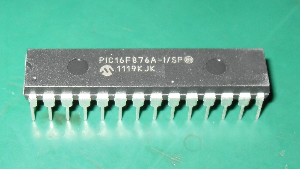
The PIC16F876A is an 8-bit microcontroller from Microchip Technology, known for its versatility and ease of use in a wide range of embedded applications. It features a RISC architecture, with a rich instruction set and extensive peripheral support. This microcontroller is ideal for use in industrial automation, consumer electronics, automotive, and home appliances.
Key Features:
- 8-bit RISC architecture
- 14-bit instruction set
- 7.37 kB (8192 words) Flash memory for program storage
- 368 bytes SRAM for data storage
- 256 bytes EEPROM for non-volatile data storage
- 22 I/O pins for interfacing with external devices
- 3 Timers (2 x 8-bit, 1 x 16-bit)
- 10-bit ADC with 8 channels
- Capture/Compare/PWM (CCP) modules
- Enhanced USART module for serial communication
- Master Synchronous Serial Port (MSSP) supporting SPI and I2C
- Watchdog Timer with dedicated on-chip RC oscillator
- Programmable code protection
- In-Circuit Serial Programming (ICSP) via two pins
Technical Specifications:
- Package Types: 28-pin PDIP, SOIC, SSOP, QFN
- Operating Voltage: 2.0V to 5.5V
- Clock Speed: Up to 20 MHz
- Flash Memory: 7.37 kB
- SRAM: 368 bytes
- EEPROM: 256 bytes
- I/O Pins: 22
- Timers: Two 8-bit, one 16-bit
- ADC Resolution: 10-bit
- ADC Channels: 8
- Operating Temperature Range: -40°C to +85°C
Applications:
- Industrial automation
- Consumer electronics
- Automotive control systems
- Home appliances
- Security systems
- Data acquisition systems
- Robotics
Usage:
- Programming:
- Program the PIC16F876A using a compatible programmer or development kit.
- Utilize ICSP for convenient in-circuit programming and debugging.
- Peripheral Configuration:
- Configure I/O pins, timers, ADC, CCP modules, and communication interfaces via software.
- Use the integrated peripherals to interface with sensors, actuators, and other devices.
- Application Development:
- Write and upload firmware to the microcontroller using development environments such as MPLAB X IDE.
- Utilize libraries and example codes to speed up the development process.
- Deployment:
- Integrate the programmed microcontroller into your electronic circuit.
- Ensure proper power supply and signal connections to avoid damage and ensure optimal performance.
Caution:
- Handle the microcontroller with care to avoid damage from electrostatic discharge (ESD).
- Verify the correct power supply voltage and connections before powering the device.
- Follow the manufacturer’s guidelines for programming and operation to ensure reliability and longevity.
Datasheet:
For detailed technical specifications, refer to the PIC16F876A Datasheet.
|
