|
Description |
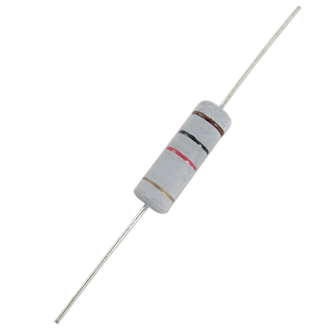
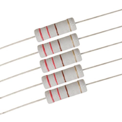
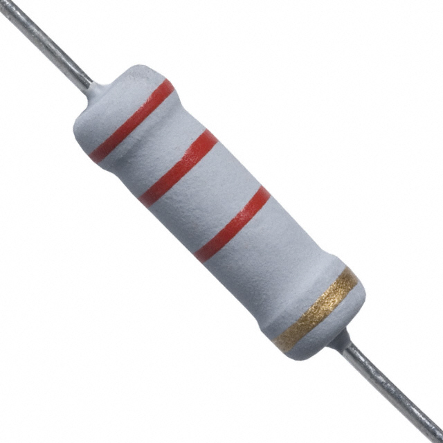
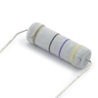
The 1KΩ 2W resistor is a fixed-value resistor designed for applications that require moderate power dissipation. It is used to limit current, divide voltage, and protect components in various electronic circuits. This resistor is suitable for power supply circuits, audio equipment, and other applications where reliable performance and high power handling are essential.
Key Features:
- Fixed resistance value of 1KΩ
- Power rating of 2 watts
- Flame-resistant coating for safety
- High reliability and stability
- Axial leads for easy mounting on printed circuit boards (PCBs)
- Suitable for a wide range of electronic applications
Technical Specifications:
- Resistance Value: 1KΩ
- Power Rating: 2W
- Tolerance: ±5% (J) or ±1% (F), depending on the model
- Temperature Coefficient: ±200 ppm/°C
- Operating Temperature Range: -55°C to +155°C
- Body Size: Approx. 5.5mm (Diameter) x 15mm (Length)
- Lead Diameter: Approx. 0.8mm
- Material: Metal oxide film or carbon film
- Maximum Working Voltage: 350V
- Maximum Overload Voltage: 600V
Applications:
- Power Supplies: Used in power supply circuits for current limiting and voltage division.
- LED Drivers: Ideal for controlling the current flow in LED circuits.
- Audio Equipment: Suitable for audio crossover networks and other audio applications.
- General Electronics: Used in a variety of electronic devices and circuits.
- Industrial Equipment: Suitable for industrial control and automation systems.
Usage:
- Identify the resistor’s resistance value and power rating by reading the color code or label.
- Solder the resistor onto the PCB or connect it into the circuit using the axial leads.
- Ensure the resistor is placed in a location that allows for adequate heat dissipation.
- Verify the resistor’s connections and test the circuit to ensure proper operation.
Caution:
- Do not exceed the resistor’s maximum power rating to avoid overheating and potential failure.
- Ensure proper ventilation and heat dissipation when using the resistor in high-power applications.
- Handle with care to prevent damage to the resistor’s leads and coating.
- Verify the resistor’s resistance value and tolerance before use in precision circuits.
|
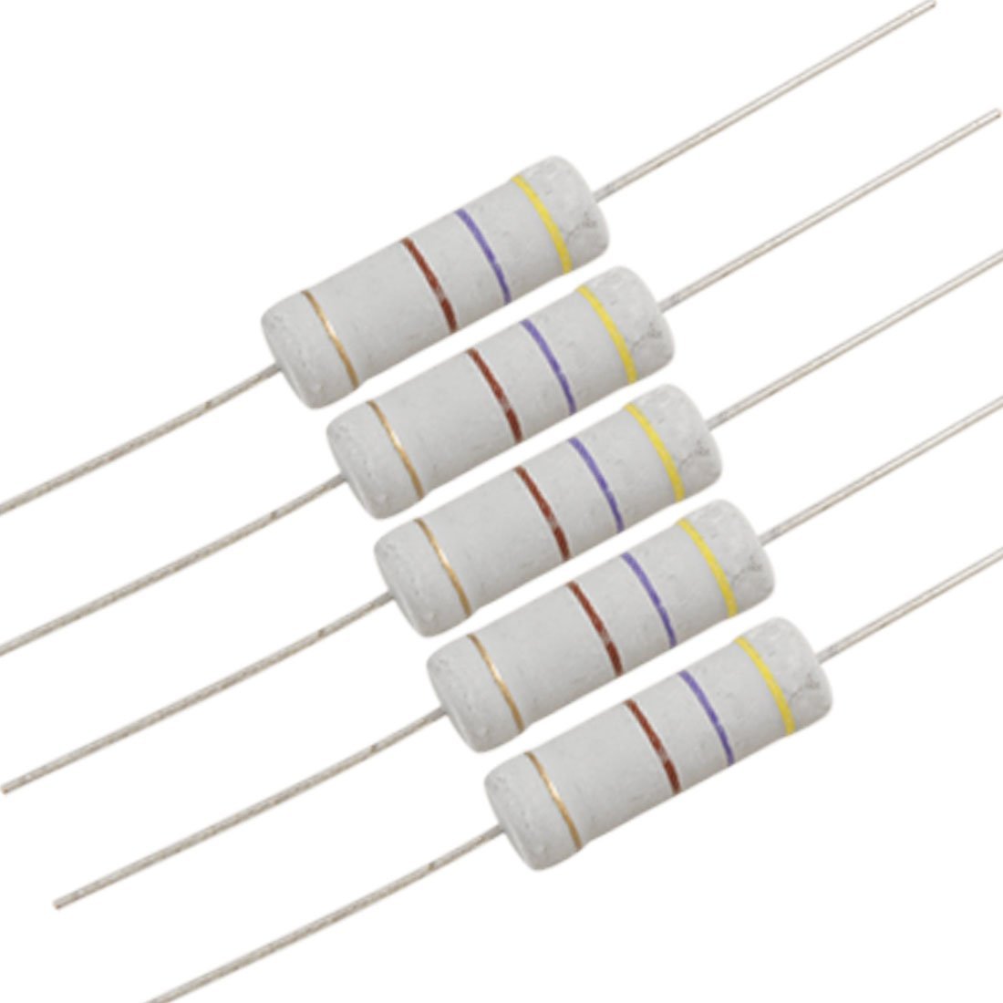
The 1MΩ 1W resistor is a fixed-value resistor designed for applications requiring moderate power dissipation. It is used to limit current, divide voltage, and protect components in various electronic circuits. This resistor is suitable for power supply circuits, audio equipment, and other applications where reliable performance and moderate power handling are essential.
Key Features:
- Fixed resistance value of 1MΩ
- Power rating of 1 watt
- Flame-resistant coating for safety
- High reliability and stability
- Axial leads for easy mounting on printed circuit boards (PCBs)
- Suitable for a wide range of electronic applications
Technical Specifications:
- Resistance Value: 1MΩ
- Power Rating: 1W
- Tolerance: ±5% (J) or ±1% (F), depending on the model
- Temperature Coefficient: ±200 ppm/°C
- Operating Temperature Range: -55°C to +155°C
- Body Size: Approx. 4.0mm (Diameter) x 11.5mm (Length)
- Lead Diameter: Approx. 0.6mm
- Material: Metal oxide film or carbon film
- Maximum Working Voltage: 250V
- Maximum Overload Voltage: 400V
Applications:
- Power Supplies: Used in power supply circuits for current limiting and voltage division.
- LED Drivers: Ideal for controlling the current flow in LED circuits.
- Audio Equipment: Suitable for audio crossover networks and other audio applications.
- General Electronics: Used in a variety of electronic devices and circuits.
- Industrial Equipment: Suitable for industrial control and automation systems.
Usage:
- Identify the resistor’s resistance value and power rating by reading the color code or label.
- Solder the resistor onto the PCB or connect it into the circuit using the axial leads.
- Ensure the resistor is placed in a location that allows for adequate heat dissipation.
- Verify the resistor’s connections and test the circuit to ensure proper operation.
Caution:
- Do not exceed the resistor’s maximum power rating to avoid overheating and potential failure.
- Ensure proper ventilation and heat dissipation when using the resistor in high-power applications.
- Handle with care to prevent damage to the resistor’s leads and coating.
- Verify the resistor’s resistance value and tolerance before use in precision circuits.
|
47K ohm 2W flame proof metal oxide resisto
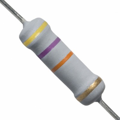
The 47KΩ 2W resistor is a fixed-value resistor designed for applications requiring high power dissipation and moderate resistance. It is commonly used in electronic circuits to limit current, divide voltage, and stabilize signals. The resistor’s robust construction ensures reliable performance in high-power and precision applications.
Key Features:
- Fixed resistance value of 47KΩ
- Power rating of 2 watts
- Flame-resistant coating for enhanced safety
- High stability and durability
- Axial leads for easy mounting on printed circuit boards (PCBs)
- Suitable for use in high-power and precision applications
Technical Specifications:
- Resistance Value: 47KΩ
- Power Rating: 2W
- Tolerance: ±5% (J) or ±1% (F), depending on the model
- Temperature Coefficient: ±200 ppm/°C
- Operating Temperature Range: -55°C to +155°C
- Body Size: Approx. 4.5mm (Diameter) x 14.5mm (Length)
- Lead Diameter: Approx. 0.8mm
- Material: Metal oxide film or carbon film
- Maximum Working Voltage: 350V
- Maximum Overload Voltage: 500V
Applications:
- Signal Processing: Ideal for use in circuits for signal conditioning and noise filtering.
- Voltage Dividers: Commonly used in voltage divider networks in electronic circuits.
- Power Supply Circuits: Applied in power supply circuits to regulate and limit current.
- General Electronics: Suitable for various electronic devices and circuits requiring high power dissipation.
Usage:
- Identify the resistor’s resistance value and power rating by reading the color code or label.
- Solder the resistor onto the PCB or integrate it into the circuit using the axial leads.
- Ensure proper placement for effective heat dissipation.
- Verify the resistor’s connections and test the circuit to ensure correct operation.
Caution:
- Do not exceed the resistor’s maximum power rating to avoid overheating and damage.
- Ensure good ventilation and heat dissipation in high-power applications.
- Handle with care to avoid damaging the resistor’s leads and coating.
- Confirm the resistor’s resistance value and tolerance before use in precision applications.
r
|
The 1kΩ 1W resistor is a fixed-value resistor designed for applications requiring moderate power dissipation. It is used to limit current, divide voltage, and protect components in various electronic circuits. This resistor is suitable for power supply circuits, audio equipment, and other applications where reliable performance and moderate power handling are essential.
Key Features:
- Fixed resistance value of 1kΩ
- Power rating of 1 watt
- Flame-resistant coating for safety
- High reliability and stability
- Axial leads for easy mounting on printed circuit boards (PCBs)
- Suitable for a wide range of electronic applications
Technical Specifications:
- Resistance Value: 1kΩ
- Power Rating: 1W
- Tolerance: ±5% (J) or ±1% (F), depending on the model
- Temperature Coefficient: ±200 ppm/°C
- Operating Temperature Range: -55°C to +155°C
- Body Size: Approx. 4.0mm (Diameter) x 11.5mm (Length)
- Lead Diameter: Approx. 0.6mm
- Material: Metal oxide film or carbon film
- Maximum Working Voltage: 250V
- Maximum Overload Voltage: 400V
Applications:
- Power Supplies: Used in power supply circuits for current limiting and voltage division.
- LED Drivers: Ideal for controlling the current flow in LED circuits.
- Audio Equipment: Suitable for audio crossover networks and other audio applications.
- General Electronics: Used in a variety of electronic devices and circuits.
- Industrial Equipment: Suitable for industrial control and automation systems.
Usage:
- Identify the resistor’s resistance value and power rating by reading the color code or label.
- Solder the resistor onto the PCB or connect it into the circuit using the axial leads.
- Ensure the resistor is placed in a location that allows for adequate heat dissipation.
- Verify the resistor’s connections and test the circuit to ensure proper operation.
Caution:
- Do not exceed the resistor’s maximum power rating to avoid overheating and potential failure.
- Ensure proper ventilation and heat dissipation when using the resistor in high-power applications.
- Handle with care to prevent damage to the resistor’s leads and coating.
- Verify the resistor’s resistance value and tolerance before use in precision circuits.
|
A 22Ω 1W resistor is a fixed resistor with a resistance value of 22 ohms and a power rating of 1 watt. It is used in electronic circuits to limit current and drop voltage, suited for applications that require moderate power dissipation.
Key Features:
- Resistance value: 22Ω (ohms)
- Power rating: 1W (watt)
- Tolerance: ±5% (typical)
- Axial leaded design for through-hole mounting
- High power dissipation capability
- Flame-retardant coating
- Stable performance with low noise
Technical Specifications:
- Resistance: 22Ω
- Power Rating: 1W
- Tolerance: ±5% (other tolerances available upon request)
- Temperature Coefficient: ±200 ppm/°C (typical)
- Operating Temperature Range: -55°C to +155°C
- Maximum Working Voltage: 250V
- Body Dimensions: Approximately 10 mm length x 4 mm diameter
- Lead Diameter: Approximately 0.8 mm
Applications:
- Power Supplies: Limiting current and voltage drop in power regulation circuits
- Audio Equipment: Reducing noise and stabilizing performance in audio amplifiers
- Industrial Controls: Managing power dissipation in control systems
- Lighting: Current limiting in LED drivers and lighting circuits
- General Electronics: Used in various electronic circuits requiring moderate power resistors
Usage:
- Identify the required resistance value and power rating for your circuit.
- Insert the resistor into the PCB or breadboard, ensuring correct orientation for through-hole components.
- Solder the leads in place if necessary, ensuring a secure and reliable connection.
- Verify the connections and test the circuit to ensure proper functionality.
Caution:
- Ensure the resistor’s power rating is adequate for your application to prevent overheating.
- Handle with care to avoid damaging the resistor or its leads.
- Avoid exceeding the maximum working voltage and power dissipation limits.
|
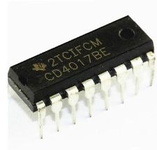
The CD4017 is a 5-stage decade counter/driver that is commonly used in sequential logic applications. It is part of the CMOS 4000 series and features high noise immunity and low power consumption. The IC is capable of counting from 0 to 9 and provides 10 decoded outputs, making it suitable for a variety of applications such as LED chasers, frequency dividers, and event counters.
Key Features:
- 5-stage decade counter with 10 decoded outputs
- High-speed operation
- Synchronous and asynchronous clear
- High noise immunity
- Low power consumption
- Wide supply voltage range
- Direct drive for LEDs
Technical Specifications:
- Operating Voltage: 3V to 15V
- Maximum Clock Frequency: 5 MHz (at Vcc = 10V)
- Output Drive Capability: 10 LSTTL loads
- Power Consumption: 0.25 mW (typical)
- Propagation Delay Time: 70 ns (at Vcc = 10V)
- Package Types: 16-pin PDIP, SOIC, TSSOP
- Operating Temperature Range: -55°C to +125°C
Pin Configuration:
- Q0 – Output 0
- Q1 – Output 1
- Q2 – Output 2
- Q3 – Output 3
- Q4 – Output 4
- Q5 – Output 5
- Q6 – Output 6
- Q7 – Output 7
- Q8 – Output 8
- Q9 – Output 9
- Clock Inhibit – Inhibits the clock input if HIGH
- Clock – Clock input
- Carry Out – Used to cascade additional counters
- Ground (GND) – Connect to system ground
- Reset – Resets the count to zero when HIGH
- Vcc – Supply voltage
Applications:
- LED chasers and sequencers
- Frequency dividers
- Event counters
- Display drivers
- Digital clocks
- Automated testing systems
- Electronic games
Usage:
- Connection:
- Connect Vcc to the supply voltage (3V to 15V) and GND to ground.
- Connect the clock input to the desired clock signal.
- Use the reset pin to reset the counter to zero when needed.
- Utilize the decoded outputs (Q0-Q9) for driving LEDs, relays, or other loads.
- Cascading:
- Use the carry-out pin to cascade multiple CD4017 ICs for higher counting ranges.
- Control:
- Use the clock inhibit pin to pause the counting operation when required.
- Implement control logic using the decoded outputs for complex sequential operations.
Caution:
- Ensure the supply voltage does not exceed the maximum rated voltage to avoid damage.
- Handle the IC carefully to prevent damage from electrostatic discharge (ESD).
- Avoid short-circuiting the output pins to prevent excessive current draw.
Datasheet:
For detailed technical specifications, refer to the CD4017 Datasheet.
|
The 470Ω 2W resistor is a fixed-value resistor designed for applications that require moderate power dissipation. It is used to limit current, divide voltage, and protect components in various electronic circuits. This resistor is suitable for power supply circuits, audio equipment, and other applications where reliable performance and high power handling are essential.
Key Features:
- Fixed resistance value of 470Ω
- Power rating of 2 watts
- Flame-resistant coating for safety
- High reliability and stability
- Axial leads for easy mounting on printed circuit boards (PCBs)
- Suitable for a wide range of electronic applications
Technical Specifications:
- Resistance Value: 470Ω
- Power Rating: 2W
- Tolerance: ±5% (J) or ±1% (F), depending on the model
- Temperature Coefficient: ±200 ppm/°C
- Operating Temperature Range: -55°C to +155°C
- Body Size: Approx. 5.5mm (Diameter) x 15mm (Length)
- Lead Diameter: Approx. 0.8mm
- Material: Metal oxide film or carbon film
- Maximum Working Voltage: 350V
- Maximum Overload Voltage: 600V
Applications:
- Power Supplies: Used in power supply circuits for current limiting and voltage division.
- LED Drivers: Ideal for controlling the current flow in LED circuits.
- Audio Equipment: Suitable for audio crossover networks and other audio applications.
- General Electronics: Used in a variety of electronic devices and circuits.
- Industrial Equipment: Suitable for industrial control and automation systems.
Usage:
- Identify the resistor’s resistance value and power rating by reading the color code or label.
- Solder the resistor onto the PCB or connect it into the circuit using the axial leads.
- Ensure the resistor is placed in a location that allows for adequate heat dissipation.
- Verify the resistor’s connections and test the circuit to ensure proper operation.
Caution:
- Do not exceed the resistor’s maximum power rating to avoid overheating and potential failure.
- Ensure proper ventilation and heat dissipation when using the resistor in high-power applications.
- Handle with care to prevent damage to the resistor’s leads and coating.
- Verify the resistor’s resistance value and tolerance before use in precision circuits.
|
The 220Ω 1W resistor is a fixed-value resistor designed for applications requiring moderate power dissipation. It is used to limit current, divide voltage, and protect components in various electronic circuits. This resistor is suitable for power supply circuits, audio equipment, and other applications where reliable performance and moderate power handling are essential.
Key Features:
- Fixed resistance value of 220Ω
- Power rating of 1 watt
- Flame-resistant coating for safety
- High reliability and stability
- Axial leads for easy mounting on printed circuit boards (PCBs)
- Suitable for a wide range of electronic applications
Technical Specifications:
- Resistance Value: 220Ω
- Power Rating: 1W
- Tolerance: ±5% (J) or ±1% (F), depending on the model
- Temperature Coefficient: ±200 ppm/°C
- Operating Temperature Range: -55°C to +155°C
- Body Size: Approx. 4.0mm (Diameter) x 11.5mm (Length)
- Lead Diameter: Approx. 0.6mm
- Material: Metal oxide film or carbon film
- Maximum Working Voltage: 250V
- Maximum Overload Voltage: 400V
Applications:
- Power Supplies: Used in power supply circuits for current limiting and voltage division.
- LED Drivers: Ideal for controlling the current flow in LED circuits.
- Audio Equipment: Suitable for audio crossover networks and other audio applications.
- General Electronics: Used in a variety of electronic devices and circuits.
- Industrial Equipment: Suitable for industrial control and automation systems.
Usage:
- Identify the resistor’s resistance value and power rating by reading the color code or label.
- Solder the resistor onto the PCB or connect it into the circuit using the axial leads.
- Ensure the resistor is placed in a location that allows for adequate heat dissipation.
- Verify the resistor’s connections and test the circuit to ensure proper operation.
Caution:
- Do not exceed the resistor’s maximum power rating to avoid overheating and potential failure.
- Ensure proper ventilation and heat dissipation when using the resistor in high-power applications.
- Handle with care to prevent damage to the resistor’s leads and coating.
- Verify the resistor’s resistance value and tolerance before use in precision circuits.
|
Description:
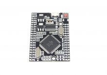
The Mega 2560 PRO with CH340 is a compact and powerful development board based on the ATmega2560 microcontroller. Designed for advanced applications, it offers extensive I/O capabilities, high processing power, and reliable USB communication via the CH340 chip. This board is ideal for projects requiring multiple interfaces, large memory, and robust performance.
Key Features:
- Microcontroller: ATmega2560 with 54 digital I/O pins, 16 analog inputs, and 4 UARTs.
- USB to Serial Communication: CH340 chip for reliable USB communication.
- Compact Design: Smaller form factor compared to standard Mega 2560 boards.
- High Memory Capacity: 256 KB Flash memory, 8 KB SRAM, and 4 KB EEPROM.
- Multiple Interfaces: I2C, SPI, and serial interfaces for versatile connectivity.
- Wide Operating Voltage Range: Supports 7-12V DC input voltage.
Technical Specifications:
- Microcontroller: ATmega2560
- Operating Voltage: 5V
- Input Voltage (recommended): 7-12V
- Digital I/O Pins: 54 (of which 15 provide PWM output)
- Analog Input Pins: 16
- DC Current per I/O Pin: 20 mA
- Flash Memory: 256 KB (8 KB used by bootloader)
- SRAM: 8 KB
- EEPROM: 4 KB
- Clock Speed: 16 MHz
- USB Controller: CH340
- Dimensions: Compact size for integration into various projects
Applications:
- Robotics: Ideal for controlling multiple motors, sensors, and other peripherals.
- Embedded Systems: Suitable for complex embedded system designs.
- IoT Projects: Can be used in Internet of Things (IoT) applications requiring extensive I/O and memory.
- Automation: Perfect for automation projects needing high processing power and multiple interfaces.
- Prototyping: Great for prototyping advanced electronics and software applications.
Datasheet:
For detailed technical information and specifications, please refer to the Mega 2560 PRO with CH340 Datasheet.
|
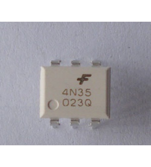
The 4N35 is a general-purpose optocoupler that consists of an infrared LED and a silicon phototransistor. It is designed to provide electrical isolation between input and output circuits while allowing signal transmission. This optocoupler is widely used in applications requiring noise isolation, signal isolation, and interface compatibility between high voltage and low voltage systems.
Key Features:
- High isolation voltage (typically 5,000 Vrms)
- Fast switching speed
- Low input current requirements
- Wide operating temperature range
- Compact and reliable design
- Compatible with various digital and analog circuits
Technical Specifications:
- Isolation Voltage: 5,000 Vrms (min)
- Input LED Forward Voltage: 1.2V (typ), 1.5V (max)
- Input LED Forward Current: 10mA (typ), 60mA (max)
- Collector-Emitter Voltage (VCEO): 30V (max)
- Collector Current (IC): 50mA (max)
- Current Transfer Ratio (CTR): 20% to 300% (at IF = 10mA, VCE = 5V)
- Rise Time (tr): 3µs (typ)
- Fall Time (tf): 2µs (typ)
- Package Type: 6-pin DIP
- Operating Temperature Range: -55°C to +100°C
Applications:
- Signal isolation in communication systems
- Switching power supplies
- Microcontroller interface isolation
- Motor control circuits
- Industrial automation systems
- Data acquisition systems
Usage:
- Circuit Design:
- Connect the anode of the input LED to the control signal source and the cathode to the ground, through a current-limiting resistor.
- Connect the collector of the phototransistor to the load or the microcontroller input, and the emitter to the ground.
- Current Limiting:
- Calculate and use an appropriate current-limiting resistor for the LED input to ensure it operates within the specified current range.
- Isolation:
- Ensure that the input and output sides of the optocoupler are properly isolated to prevent electrical interference and maintain safety.
- Testing:
- Verify the functionality of the optocoupler by applying a control signal to the LED input and observing the output response.
Caution:
- Handle the optocoupler with care to avoid damage from electrostatic discharge (ESD).
- Verify the electrical ratings and ensure the device operates within specified limits to avoid damage.
- Keep the input and output circuits isolated to maintain the integrity of the isolation barrier.
Datasheet:
For detailed technical specifications, refer to the 4N35 Datasheet.
|
The L7824 is a three-terminal positive voltage regulator that provides a fixed output of +24V. Designed for reliable and efficient voltage regulation, it is suitable for powering a range of electronic circuits and devices from a higher input voltage source. This regulator can supply up to 1.5A of current and includes built-in protection features to safeguard against thermal overload and short circuits.
Key Features:
- Fixed positive output voltage of +24V
- Capable of delivering up to 1.5A of current
- High voltage regulation with minimal dropout
- Built-in thermal overload and short-circuit protection
- Easy to use with minimal external components
- Ideal for applications requiring a stable +24V power supply
Technical Specifications:
- Output Voltage: +24V
- Maximum Output Current: 1.5A
- Input Voltage Range: Up to +35V
- Dropout Voltage: 2V (typical)
- Line Regulation: 0.01% (typical)
- Load Regulation: 0.1% (typical)
- Package Type: TO-220, D2PAK
Applications:
- Positive voltage power supplies
- Voltage regulation in electronic circuits
- Power management in devices requiring +24V
- Replacement for higher voltage linear power supplies
Usage:
- Connect the positive input voltage to the input terminal (IN).
- Connect the output terminal (OUT) to the load or circuit requiring +24V.
- Ensure the ground terminal (GND) is connected to the system ground.
- Use a heatsink if necessary to handle thermal dissipation, especially under high load conditions.
Caution:
- Do not exceed the maximum input voltage rating.
- Ensure proper heat dissipation to prevent overheating.
- Verify correct polarity to avoid damage to the regulator and connected components.
Datasheet:
For detailed technical specifications, refer to the L7824 Datasheet.
|
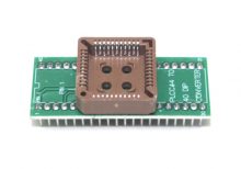
The PLC44 to DIP40 IC Socket Adapter is designed to convert a 44-pin PLCC (Plastic Leaded Chip Carrier) IC package into a 40-pin DIP (Dual Inline Package) socket configuration. This adapter enables the use of PLCC ICs in DIP socket-compatible PCBs and prototyping setups, simplifying integration and testing.
Key Features:
- Convenient Conversion: Adapts a 44-pin PLCC IC for use with a 40-pin DIP socket.
- High-Quality Construction: Built with durable materials to ensure reliable connections and longevity.
- Gold-Plated Contacts: Provides excellent conductivity and corrosion resistance.
- Compact Form Factor: Suitable for use with standard breadboards and PCB mountings.
- Easy Installation: Allows for quick and straightforward installation and removal of ICs.
Technical Specifications:
- Package Type: PLC44 to DIP40
- Pin Pitch (PLCC): 1.27mm
- Pin Pitch (DIP): 2.54mm
- Material: FR4 PCB, Gold-plated contacts
- Dimensions: Varies by model
- Weight: Lightweight design
- Temperature Range: -40°C to +85°C
- Mounting Type: Through-hole
Applications:
- Prototyping: Enables the use of PLCC ICs on DIP-compatible breadboards and prototype boards.
- Development: Facilitates the integration of PLCC devices into DIP-based circuit designs.
- Repair and Replacement: Useful for adapting PLCC ICs in existing DIP-based systems or repairs.
- Educational Use: Ideal for demonstrating the use and conversion of different IC package types.
|
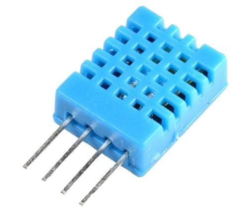
The DHT11 is a basic, ultra-low-cost digital temperature and humidity sensor. It uses a capacitive humidity sensor and a thermistor to measure the surrounding air and outputs a digital signal on the data pin. It’s simple to use but requires careful timing to grab data. It’s perfect for DIY projects, weather stations, and other applications where accurate and reliable temperature and humidity readings are needed.
Key Features:
- Temperature Range: 0-50°C with ±2°C accuracy
- Humidity Range: 20-80% RH with ±5% RH accuracy
- Low Power Consumption: Efficient for battery-operated applications
- Single Wire Digital Interface: Easy to interface with microcontrollers
- Pre-calibrated: No need for additional calibration
- Compact Size: Suitable for compact projects and devices
Technical Specifications:
- Temperature Range: 0-50°C (32-122°F)
- Humidity Range: 20-80% RH
- Temperature Accuracy: ±2°C
- Humidity Accuracy: ±5% RH
- Operating Voltage: 3.3V to 5.5V
- Max Current: 2.5mA
- Output: Digital signal via 1-wire protocol
- Dimensions: 15.5mm x 12mm x 5.5mm
Applications:
- Weather Stations: Monitor and log temperature and humidity levels.
- Home Automation: Control HVAC systems based on environmental conditions.
- Greenhouses: Maintain optimal growing conditions for plants.
- DIY Projects: Perfect for hobbyists building custom sensors and gadgets.
- Data Loggers: Record environmental data over time for analysis.
- Educational Projects: Teach students about sensors and data acquisition.
Usage:
- Wiring: Connect the VCC pin to 3.3V or 5V, GND to ground, and the DATA pin to a digital input on your microcontroller.
- Library Integration: Use libraries available for platforms like Arduino or Raspberry Pi to simplify reading data from the sensor.
- Coding: Write code to initialize the sensor and read temperature and humidity data.
- Data Processing: Process and use the sensor data in your application as needed, such as displaying it on an LCD or sending it to a web server.
Caution:
- Power Supply: Ensure the sensor is supplied with the correct voltage to avoid damage.
- Environmental Conditions: Keep the sensor in a dust-free, non-condensing environment for accurate readings.
- Wiring Length: Minimize the length of wiring between the sensor and the microcontroller to maintain signal integrity.
Datasheet:
For detailed technical specifications, refer to the DHT11 Datasheet.
|
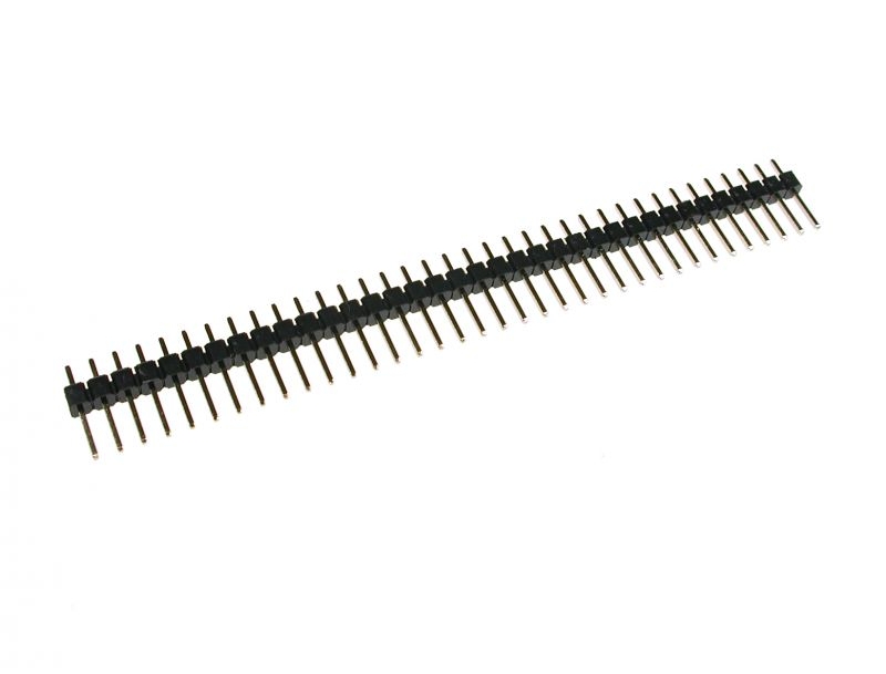
Male headers are versatile connectors used in a wide range of electronic applications for creating pluggable connections between PCBs (Printed Circuit Boards) and other components. These headers consist of a row (or rows) of pins that can be easily soldered onto a PCB, providing a reliable and reusable connection point for various electronic modules and wires.
Key Features:
- Available in various pin configurations (single, double, triple row, etc.)
- Standard 2.54mm (0.1 inch) pin pitch
- Compatible with solderless breadboards and female headers
- Gold-plated or tin-plated pins for improved conductivity and durability
- Suitable for both through-hole and surface mount applications
Technical Specifications:
- Pin Configuration: Single row, double row, etc. (varies by product)
- Pin Pitch: 2.54mm (0.1 inch)
- Pin Length: Typically 6mm to 12mm (varies by product)
- Pin Material: Brass with gold or tin plating
- Insulator Material: Plastic (typically black)
- Operating Temperature Range: -40°C to +105°C (varies by product)
- Current Rating: Typically up to 3A per pin (varies by product)
Applications:
- PCB interconnections
- Prototyping and breadboarding
- Modular electronics projects
- Embedded systems
- Connector interfaces for sensors, displays, and other peripherals
Usage:
- Select the appropriate male header configuration for your application (single row, double row, etc.).
- Solder the male header onto the PCB, ensuring proper alignment with the corresponding holes or pads.
- Insert the male header pins into a matching female header, breadboard, or connector to create a secure electrical connection.
- Ensure all connections are firm and stable before powering the circuit.
Caution:
- Verify the pin pitch and configuration to match the corresponding connectors or headers.
- Handle the pins carefully to avoid bending or damage during installation.
- Ensure proper soldering techniques to maintain reliable connections and prevent shorts.
Datasheet:
For detailed technical specifications, refer to the specific product datasheet provided by the manufacturer.
|
The P87C51 is an 8-bit microcontroller from the MCS-51 family, widely used in embedded systems and applications requiring control and automation. It features a robust set of peripherals and is compatible with the standard 8051 instruction set, making it suitable for various industrial, consumer, and automotive applications.
Key Features:
- 8-bit microcontroller based on the MCS-51 architecture
- 4KB of in-system programmable ROM
- 128 bytes of on-chip RAM
- 32 programmable I/O lines
- Two 16-bit timer/counters
- Full-duplex UART for serial communication
- On-chip oscillator and clock circuitry
- Interrupt support with two priority levels
- Watchdog timer for system reliability
- Low-power idle and power-down modes
Technical Specifications:
- CPU: 8-bit 8051 core
- ROM: 4KB
- RAM: 128 bytes
- EEPROM: None (external EEPROM can be used if needed)
- I/O Pins: 32 (four 8-bit ports)
- Timers/Counters: Two 16-bit
- Serial Communication: UART
- Operating Voltage: 4.0V to 5.5V
- Clock Frequency: Up to 24 MHz
- Power Consumption: Low power modes available
- Operating Temperature Range: -40°C to +85°C
- Package Type: DIP-40, PLCC-44, or QFP-44
Applications:
- Industrial control systems
- Consumer electronics
- Automotive systems
- Home automation
- Robotics
- Data acquisition systems
Usage:
- Program the P87C51 using an appropriate programmer with the desired firmware.
- Connect the necessary peripherals and sensors to the microcontroller’s I/O pins.
- Configure the microcontroller’s settings and features via software.
- Integrate the microcontroller into your electronic circuit for specific tasks and control functions.
Caution:
- Ensure proper handling and storage to avoid damage from electrostatic discharge (ESD).
- Verify correct power supply voltage and connections before powering the device.
- Follow the manufacturer’s guidelines for programming and operation.
Datasheet:
For detailed technical specifications, refer to the P87C51 Datasheet.
|
The 2.2kΩ 1W resistor is a fixed-value resistor designed for applications requiring moderate power dissipation. It is used to limit current, divide voltage, and protect components in various electronic circuits. This resistor is suitable for power supply circuits, audio equipment, and other applications where reliable performance and moderate power handling are essential.
Key Features:
- Fixed resistance value of 2.2kΩ
- Power rating of 1 watt
- Flame-resistant coating for safety
- High reliability and stability
- Axial leads for easy mounting on printed circuit boards (PCBs)
- Suitable for a wide range of electronic applications
Technical Specifications:
- Resistance Value: 2.2kΩ
- Power Rating: 1W
- Tolerance: ±5% (J) or ±1% (F), depending on the model
- Temperature Coefficient: ±200 ppm/°C
- Operating Temperature Range: -55°C to +155°C
- Body Size: Approx. 4.0mm (Diameter) x 11.5mm (Length)
- Lead Diameter: Approx. 0.6mm
- Material: Metal oxide film or carbon film
- Maximum Working Voltage: 250V
- Maximum Overload Voltage: 400V
Applications:
- Power Supplies: Used in power supply circuits for current limiting and voltage division.
- LED Drivers: Ideal for controlling the current flow in LED circuits.
- Audio Equipment: Suitable for audio crossover networks and other audio applications.
- General Electronics: Used in a variety of electronic devices and circuits.
- Industrial Equipment: Suitable for industrial control and automation systems.
Usage:
- Identify the resistor’s resistance value and power rating by reading the color code or label.
- Solder the resistor onto the PCB or connect it into the circuit using the axial leads.
- Ensure the resistor is placed in a location that allows for adequate heat dissipation.
- Verify the resistor’s connections and test the circuit to ensure proper operation.
Caution:
- Do not exceed the resistor’s maximum power rating to avoid overheating and potential failure.
- Ensure proper ventilation and heat dissipation when using the resistor in high-power applications.
- Handle with care to prevent damage to the resistor’s leads and coating.
- Verify the resistor’s resistance value and tolerance before use in precision circuits.
|
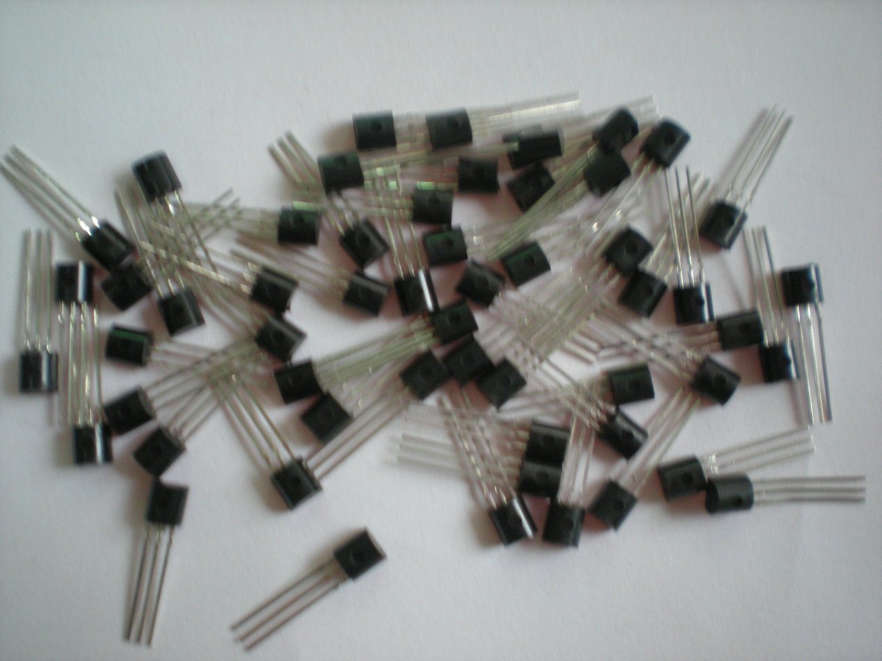
The S9014 is an NPN bipolar junction transistor (BJT) designed for general-purpose applications, including amplification and switching. It features high current gain and low noise, making it suitable for low-power electronic circuits. Its compact TO-92 package ensures ease of integration into various designs.
Key Features:
- Type: NPN Bipolar Junction Transistor (BJT)
- High Gain: High current gain (hFE) for effective amplification
- Low Noise: Suitable for low-noise applications
- Compact Package: Available in a TO-92 package for ease of use
Technical Specifications:
- Collector-Emitter Voltage (Vce): 50V
- Collector-Base Voltage (Vcb): 50V
- Emitter-Base Voltage (Veb): 6V
- Collector Current (Ic): 500mA
- Power Dissipation (Ptot): 400mW
- DC Current Gain (hFE): 100 to 600
- Transition Frequency (ft): 150MHz
- Package Type: TO-92
Applications:
- Signal Amplification: Ideal for low-power amplification circuits
- Switching: Suitable for low-power switching applications
- Audio Circuits: Used in audio frequency amplification and processing
- General Electronics: Commonly used in general-purpose electronic circuits and projects
Usage:
- Circuit Design: Integrate the S9014 transistor into your circuit based on the desired application.
- Biasing: Properly bias the transistor to ensure effective operation in amplification or switching roles.
- Connection: Connect the collector, base, and emitter terminals according to your circuit design.
- Testing: Verify the circuit operation to ensure the transistor is performing as expected.
Caution:
- Voltage and Current Ratings: Do not exceed the maximum rated voltage and current to avoid damage.
- Heat Management: Ensure adequate cooling to prevent overheating during operation.
- Handling: Handle with care to avoid damage from electrostatic discharge (ESD).
Datasheet:
For detailed technical specifications, refer to the S9014 Transistor Datasheet.
|
The 2.2kΩ 1/4W resistor is a fixed-value resistor designed to provide a resistance of 2,200 ohms (2.2 kilohms) with a power rating of 1/4 watt (0.25W). This resistor is commonly used in electronic circuits for applications such as current limiting, voltage division, and signal processing. It offers dependable performance and is suitable for a wide range of electronic projects and devices.
Key Features:
- Resistance value of 2.2kΩ (2,200 ohms)
- Power rating of 1/4 watt (0.25W)
- High stability and reliability
- Low tolerance variations
- Suitable for various electronic applications
Technical Specifications:
- Resistance Value: 2.2kΩ (2,200 ohms)
- Power Rating: 1/4W (0.25W)
- Tolerance: ±5% (standard tolerance; other tolerances may be available)
- Temperature Coefficient: ±100 ppm/°C (typical)
- Operating Temperature Range: -55°C to +155°C
- Body Color: Typically brown or blue (varies by manufacturer)
- Lead Material: Tin-plated copper
- Dimensions: Standard axial lead dimensions, typically 2.4mm in diameter and 6.3mm in length (may vary slightly by manufacturer)
Applications:
- Current Limiting: Controls current flow to protect sensitive components.
- Voltage Division: Used in voltage dividers for signal processing and measurement.
- Load Resistor: Provides a load in electronic circuits and power supplies.
- Biasing: Suitable for biasing transistors and other active components.
- General Purpose: Ideal for various electronic devices and systems.
Usage:
- Identify the resistor value using its color bands or markings.
- Solder the resistor into the circuit, ensuring proper orientation of the leads.
- Verify the resistor’s connections to ensure it is correctly integrated into the circuit.
Caution:
- Avoid exceeding the resistor’s power rating to prevent overheating and damage.
- Handle with care to avoid bending or breaking the leads.
- Ensure that the resistor value and tolerance meet the specific requirements of your application.
|
A 47Ω 1W resistor is a fixed resistor with a resistance value of 47 ohms and a power rating of 1 watt. It is used to limit current and drop voltage in electronic circuits, designed for applications with moderate power dissipation needs.
Key Features:
- Resistance value: 47Ω (ohms)
- Power rating: 1W (watt)
- Tolerance: ±5% (typical)
- Axial leaded design for through-hole mounting
- High power dissipation capability
- Flame-retardant coating
- Stable performance with low noise
Technical Specifications:
- Resistance: 47Ω
- Power Rating: 1W
- Tolerance: ±5% (other tolerances available upon request)
- Temperature Coefficient: ±200 ppm/°C (typical)
- Operating Temperature Range: -55°C to +155°C
- Maximum Working Voltage: 250V
- Body Dimensions: Approximately 10 mm length x 4 mm diameter
- Lead Diameter: Approximately 0.8 mm
Applications:
- Power Supplies: Limiting current and voltage drop in power regulation circuits
- Audio Equipment: Reducing noise and stabilizing performance in audio amplifiers
- Industrial Controls: Managing power dissipation in control systems
- Lighting: Current limiting in LED drivers and lighting circuits
- General Electronics: Used in various electronic circuits requiring moderate power resistors
Usage:
- Identify the required resistance value and power rating for your circuit.
- Insert the resistor into the PCB or breadboard, ensuring correct orientation for through-hole components.
- Solder the leads in place if necessary, ensuring a secure and reliable connection.
- Verify the connections and test the circuit to ensure proper functionality.
Caution:
- Ensure the resistor’s power rating is adequate for your application to prevent overheating.
- Handle with care to avoid damaging the resistor or its leads.
- Avoid exceeding the maximum working voltage and power dissipation limits.
|
The STM8S Development Board is a comprehensive platform designed for developing and prototyping with the STM8S series microcontrollers. It provides a robust set of features and peripherals to facilitate a wide range of applications, from simple embedded projects to complex industrial control systems. The board offers easy access to all the microcontroller’s functionalities and includes a variety of interfaces and connectors to enhance development efficiency.
Key Features:
- Microcontroller: Based on the STM8S series microcontroller.
- Peripheral Interfaces: Multiple GPIOs, UART, I2C, SPI, and ADC/DAC interfaces.
- Power Supply Options: Supports multiple power supply options, including USB and external sources.
- On-Board Debugging: Integrated SWIM interface for debugging and programming.
- Expandable: Pin headers for easy expansion with additional modules and shields.
- User-Friendly Design: Includes user LEDs, push buttons, and a reset button for easy development and testing.
- Software Support: Compatible with various IDEs and development tools, including STM8S firmware libraries.
Technical Specifications:
- Microcontroller: STM8S series
- Operating Voltage: 3.3V to 5V
- Communication Interfaces: UART, I2C, SPI
- Analog Inputs: Multiple ADC channels
- Digital I/O: Multiple GPIO pins
- Clock Speed: Up to 16MHz
- Memory: Flash, RAM, and EEPROM (varies by specific STM8S model)
- Dimensions: Compact and portable design
Applications:
- Embedded Systems: Ideal for developing and prototyping embedded systems.
- Industrial Control: Suitable for industrial automation and control applications.
- Education and Training: Perfect for educational purposes and hands-on learning.
- Home Automation: Can be used in home automation projects.
- Consumer Electronics: Applicable in various consumer electronic devices.
Datasheet:
For detailed technical specifications, refer to the STM8S Development Board Datasheet.
|
Description:
The LF412CN is a high-performance dual operational amplifier featuring JFET input stages for low input bias and offset currents. It provides low noise and high slew rate, making it suitable for precision analog signal processing, audio applications, and high impedance sensor interfaces.
Key Features:
- Dual operational amplifier in a single package
- JFET input stages for high input impedance
- Low input bias current: 30 pA (typical)
- Low input offset voltage: 3 mV (max)
- Wide bandwidth: 4 MHz (typical)
- High slew rate: 13 V/µs
- Low noise density: 8 nV/√Hz at 1 kHz
- Single supply operation: 3V to 36V or dual supply operation: ±1.5V to ±18V
Technical Specifications:
- Package Type: DIP-8
- Supply Voltage Range: ±3V to ±18V
- Input Voltage Range: ±15V (differential)
- Input Offset Current: 3 nA (typical)
- Common-Mode Rejection Ratio (CMRR): 100 dB (typical)
- Power Consumption: 1.3 mA per amplifier
- Operating Temperature Range: 0°C to +70°C
- Dimensions: 9.81 mm x 6.35 mm x 3.56 mm
- Weight: 0.35 g
Applications:
- Audio Systems: Used in audio preamplifiers, equalizers, and mixers.
- Sensor Interfaces: Interfaces with high-impedance sensors in measurement and control systems.
- Active Filters: Used in active filter circuits for frequency selection.
- Instrumentation: Suitable for precision measurement and data acquisition systems.
- Signal Processing: Used in analog signal conditioning and amplification applications.
Datasheet:
For detailed technical information, refer to the LF412CN Datasheet.
|
The 2.4G WiFi Built-in Transmitter Antenna is an integrated antenna designed for wireless communication in the 2.4 GHz frequency band. It is commonly used in WiFi modules and devices to transmit and receive signals within the 2.4 GHz ISM (Industrial, Scientific, and Medical) band. The built-in design allows for compact integration into various devices, offering convenience and space-saving benefits.
Key Features:
- Frequency Band: 2.4 GHz ISM band (2.4 to 2.5 GHz)
- Integration: Built-in design for compact and space-saving applications
- Antenna Type: Typically monopole or PCB trace antenna
- Performance: Optimized for WiFi communication with good range and signal strength
- Connector Type: No external connector (integrated into the device)
- Material: Generally made from materials that offer good conductivity and durability
Technical Specifications:
- Frequency Band: 2.4 GHz (2.4 to 2.5 GHz)
- Antenna Type: Monopole, PCB trace, or other built-in designs
- Impedance: 50 ohms
- Gain: Typically 2 dBi to 5 dBi (varies by design)
- Polarization: Linear or vertical polarization
- Power Handling: Designed to handle standard WiFi transmission power levels
- Dimensions: Integrated into the device, size varies depending on design
Applications:
- WiFi Modules: Used in WiFi modules and devices for wireless communication.
- Consumer Electronics: Integrated into consumer electronics such as routers, smartphones, and tablets.
- Embedded Systems: Suitable for embedded systems requiring built-in wireless communication.
- IoT Devices: Applied in Internet of Things (IoT) devices where space is limited and built-in antennas are preferred.
Datasheet:
For detailed technical information, refer to the datasheet of the specific 2.4G WiFi built-in transmitter antenna used in the device, as specifications can vary based on the manufacturer and design.
|
The S8550 is a PNP bipolar junction transistor (BJT) designed for general-purpose low-power switching and amplification. Known for its high current gain and low noise, the S8550 is suitable for various electronic applications, including signal processing, low-power amplification, and switching circuits.
Key Features:
- Type: PNP Bipolar Junction Transistor (BJT)
- High Gain: Provides high current gain (hFE) for effective signal amplification
- Low Noise: Suitable for low-noise applications
- Compact Package: Available in a TO-92 package, ideal for space-constrained designs
Technical Specifications:
- Collector-Emitter Voltage (Vce): -25V
- Collector-Base Voltage (Vcb): -40V
- Emitter-Base Voltage (Veb): -5V
- Collector Current (Ic): -700mA
- Power Dissipation (Ptot): 625mW
- DC Current Gain (hFE): 85 to 300
- Transition Frequency (ft): 100MHz
- Package Type: TO-92
Applications:
- Signal Amplification: Ideal for low-power amplification circuits
- Switching: Suitable for general-purpose switching applications
- Audio Circuits: Effective in audio signal processing and low-power amplification
- General Purpose: Versatile for various electronic applications and projects
Usage:
- Circuit Design: Integrate the S8550 transistor into your circuit based on your specific application requirements.
- Biasing: Properly bias the transistor to ensure optimal performance for amplification or switching.
- Connection: Connect the collector, base, and emitter terminals as per your circuit design.
- Testing: Verify the transistor’s operation in your circuit to ensure it functions correctly.
Caution:
- Voltage and Current Ratings: Adhere to the maximum voltage and current ratings to prevent damage.
- Heat Management: Ensure adequate heat dissipation to avoid overheating, especially in high-current applications.
- Static Electricity: Handle with care to avoid damage from electrostatic discharge (ESD).
Datasheet:
For detailed technical specifications, refer to the S8550 Transistor Datasheet.
|
