|
Description |
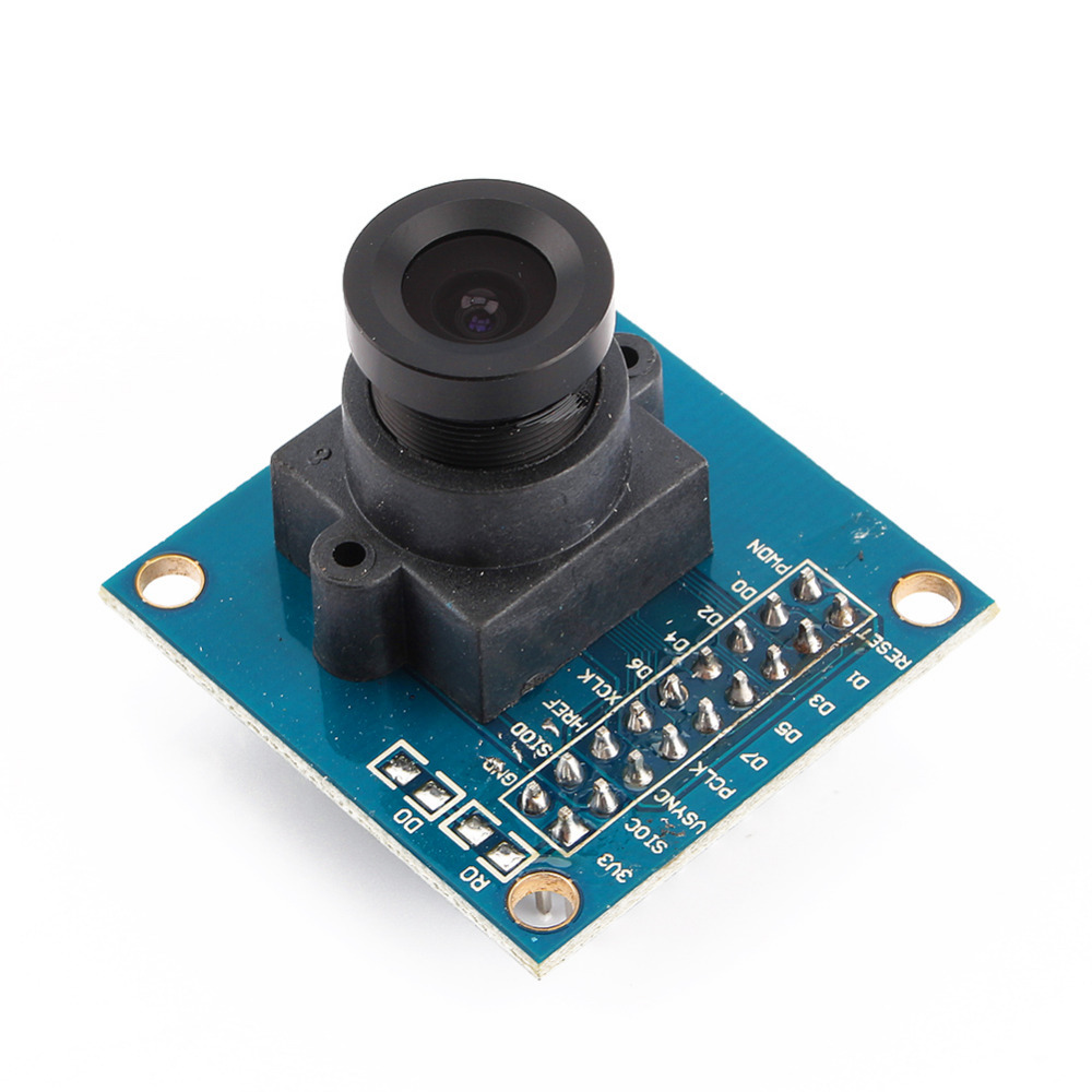
The OV7670 Camera Module is a low-cost camera module designed for use with Arduino and other microcontroller platforms. It features the OV7670 image sensor, which provides basic image capture capabilities suitable for low-resolution and hobbyist applications. This module is ideal for educational projects, DIY electronics, and simple image processing tasks.
Key Features:
- VGA (640×480) resolution capability
- Low power consumption
- Small form factor, easy to integrate with Arduino
- Includes an integrated image sensor (OV7670)
- Supports various output formats, including RGB565 and YUV422
- Built-in FIFO buffer to store image data temporarily
Technical Specifications:
- Image Sensor: OV7670 CMOS
- Resolution: VGA (640×480 pixels)
- Output Formats: RGB565, YUV422
- Power Supply: 3.3V DC (requires voltage regulator for Arduino 5V supply)
- Interface: 8-bit parallel data bus
- Operating Temperature Range: -20°C to +70°C
- Frame Rate: Up to 30 frames per second (fps) at VGA resolution
- Lens Type: Fixed-focus lens
Applications:
- Basic image capture and processing
- Educational and experimental projects involving image processing
- Low-resolution video streaming
- Simple security or surveillance systems
- Integration with Arduino for image-related applications
Usage:
- Connection: Connect the OV7670 module to the Arduino using the provided pin headers. Typically, connections include power (3.3V), ground, and data lines.
- Configuration: Use Arduino libraries and example code to configure the camera module and capture images. The module usually requires initialization and setup via I2C or SPI.
- Processing: Retrieve image data from the module and process it using Arduino or other compatible microcontrollers.
- Integration: Integrate the camera module into your project to enable image capturing or video streaming functionality.
Caution:
- The OV7670 operates at 3.3V, so be careful not to apply 5V directly to the module to avoid damage.
- Properly handle and secure the module to avoid damage to the delicate components.
- Ensure correct wiring and connections according to the module’s datasheet to avoid communication issues.
Datasheet:
For detailed technical specifications, refer to the OV7670 Camera Module Datasheet.
|
The Arduino Nano V3.0 is a compact, breadboard-friendly microcontroller board based on the ATmega328P. It is part of the Arduino platform and is designed for use in small projects and prototyping. The board includes a USB cable for easy connection to a computer for programming and power.
Key Features:
- ATmega328P microcontroller
- Compact size with 30mm x 18mm dimensions
- 22 digital I/O pins, of which 6 can be used as PWM outputs
- 8 analog input pins
- 32 KB Flash memory for program storage
- 2 KB SRAM for data storage
- 1 KB EEPROM for non-volatile data storage
- Built-in USB interface for easy programming
- Compatible with Arduino IDE for development
Technical Specifications:
- Microcontroller: ATmega328P
- Operating Voltage: 5V
- Input Voltage: 7-12V (through the power jack or USB)
- Digital I/O Pins: 22
- PWM Output Pins: 6
- Analog Input Pins: 8
- Flash Memory: 32 KB
- SRAM: 2 KB
- EEPROM: 1 KB
- Clock Speed: 16 MHz
- USB Interface: Mini-USB
- Dimensions: 30mm x 18mm
Applications:
- Prototyping and development for electronics projects
- Embedded systems and automation
- Robotics
- Sensor interfacing and data acquisition
- Educational projects and learning
Usage:
- Connection: Connect the Arduino Nano V3.0 to your computer using the included USB cable. The USB cable is used for both power and programming.
- Programming: Use the Arduino IDE to write and upload code to the board via the USB connection.
- Connection to Peripherals: Utilize the digital and analog I/O pins to connect sensors, actuators, and other peripherals.
- Power Supply: The board can be powered through the USB connection or via an external power source connected to the VIN pin.
Caution:
- Ensure correct voltage levels are used to avoid damaging the board. The recommended input voltage is 7-12V.
- Avoid short-circuiting the pins and connections.
- Handle the board and USB cable with care to prevent physical damage.
Datasheet:
For detailed technical specifications and pin configuration, refer to the Arduino Nano V3.0 Datasheet.
|
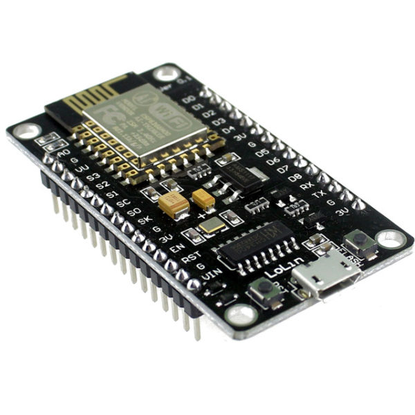
The ESP8266 NodeMcu LUA WiFi Development Board is an open-source IoT platform. It integrates the ESP8266 WiFi module, which allows for easy development of WiFi-based applications. The board includes the Lua scripting language for programming, enabling quick and efficient development. This development board is highly suitable for beginners and professionals looking to build IoT projects due to its simplicity, low cost, and robust capabilities.
Key Features:
- WiFi Module: Integrated ESP8266 with full TCP/IP stack and microcontroller capability
- Programming Language: Lua scripting language support
- GPIO: Multiple GPIO pins available for connecting sensors and actuators
- USB Interface: On-board USB to serial interface for easy programming
- Memory: 4MB Flash Memory
- Power Supply: Can be powered via micro USB or external power supply
- Built-in Antenna: On-board WiFi antenna for wireless connectivity
- Compact Size: Small form factor for easy integration into projects
Technical Specifications:
- Dimensions: 48 mm x 26 mm
- Weight: Approximately 10 g
- Operating Voltage: 3.3V
- Digital I/O Pins: 11
- Analog Input Pins: 1 (max input 3.2V)
- Clock Speed: 80 MHz
- Flash Memory: 4MB
- USB to UART: CP2102 or CH340G
- Power Consumption:
- Deep Sleep: <10 μA
- Light Sleep: <1 mA
- Modem Sleep: ~15 mA
- Active Mode: ~70 mA
- WiFi Standards: 802.11 b/g/n
- Connector Types: Micro USB, GPIO headers
Applications:
- IoT Projects: Ideal for developing Internet of Things applications with WiFi connectivity.
- Home Automation: Control and monitor home appliances and systems remotely.
- Prototyping: Rapid development and testing of WiFi-enabled prototypes.
- Wireless Sensor Networks: Creating networks of sensors with real-time data collection and communication.
- Smart Devices: Integrating WiFi capabilities into various smart devices and gadgets.
Datasheet:
For detailed technical information, refer to the ESP8266 NodeMcu LUA WiFi Development Board Datasheet.
|
The Arduino Pro Micro is a compact and versatile microcontroller board based on the ATmega32U4 microchip. It is part of the Arduino family and designed for projects where space is limited. The Pro Micro board features built-in USB capabilities, allowing it to emulate a keyboard, mouse, or other USB devices, making it suitable for a wide range of applications including custom input devices and embedded systems.
Key Features:
- Microcontroller: ATmega32U4
- Operating Voltage: 5V
- Input Voltage (recommended): 7-12V
- Digital I/O Pins: 18
- Analog Input Pins: 9
- Flash Memory: 32 KB (ATmega32U4), of which 4 KB used by bootloader
- SRAM: 2.5 KB
- EEPROM: 1 KB
- Clock Speed: 16 MHz
- USB: Built-in USB functionality for direct connection to computers and emulation of USB devices
Technical Specifications:
- Dimensions: 33 mm x 18 mm
- Weight: Approximately 8 g
- Communication: UART, SPI, I2C, USB
- On-board LEDs: TX, RX, Power, and one user-defined LED
- Power:
- DC Current per I/O Pin: 40 mA
- DC Current for 3.3V Pin: 50 mA
- Connectors:
- USB Micro-B for programming and power
- 6-pin header for serial communication
- Pins for additional communication interfaces and power
Applications:
- Custom Input Devices: Can be used to create custom keyboards, mice, and other input devices.
- Embedded Systems: Suitable for small-scale embedded projects where USB connectivity is required.
- Prototyping: Ideal for rapid prototyping and development due to its compact size and USB capability.
- IoT Projects: Can be integrated into Internet of Things (IoT) devices for various control and monitoring applications.
- Wearables: Perfect for wearable electronics and projects requiring a small form factor.
Datasheet:
For detailed technical information, refer to the Arduino Pro Micro Datasheet.
|
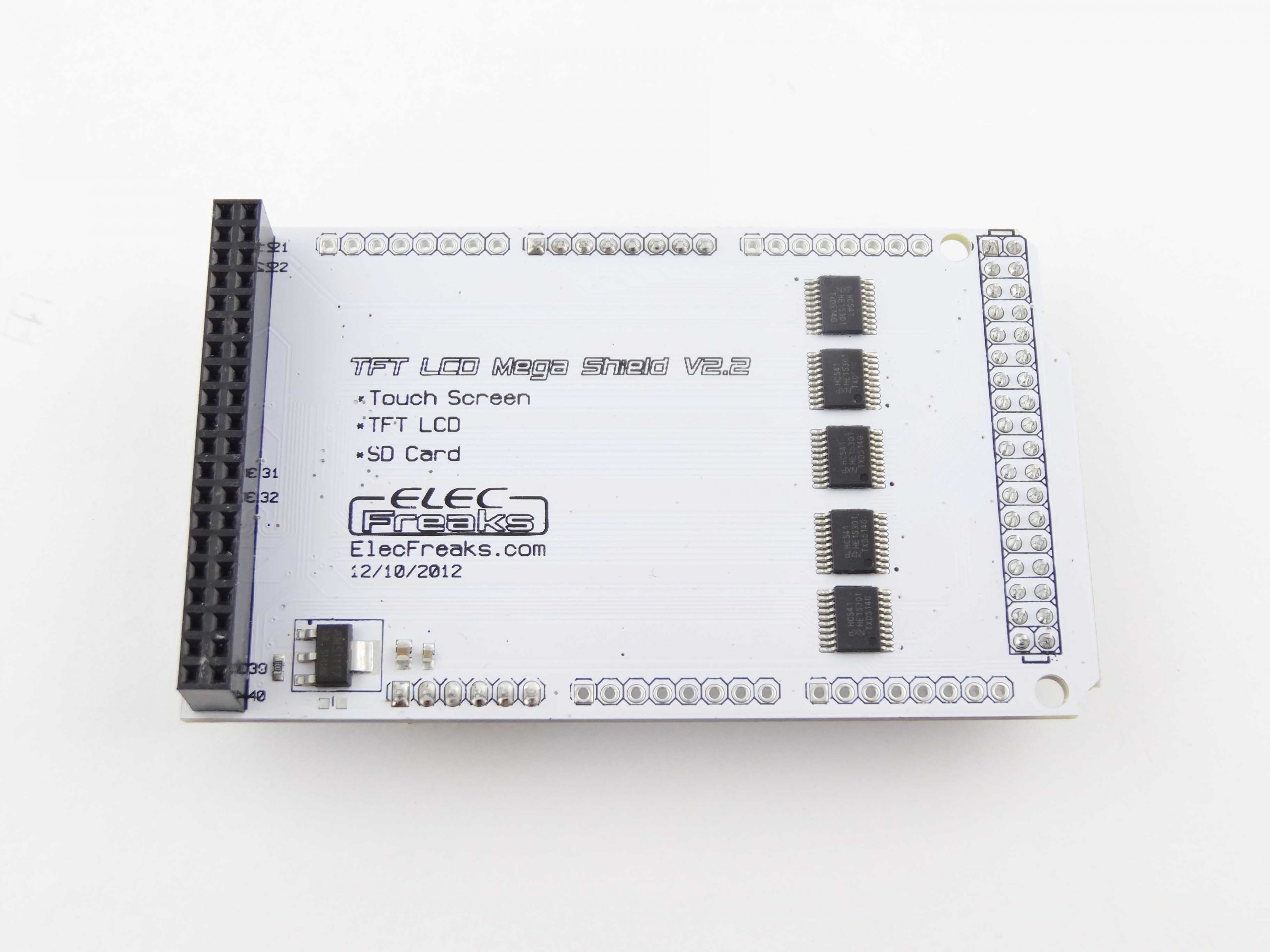
The TFT Arduino Mega Shield is an easy-to-use, plug-and-play shield designed to interface with TFT displays, allowing for high-quality graphical displays on your Arduino Mega projects. This shield simplifies the connection between the Arduino Mega and TFT LCDs, enabling you to create visually appealing user interfaces for your projects.
Key Features:
- Easy Integration: Simplifies connection of TFT displays to Arduino Mega
- High-Quality Graphics: Supports high-resolution TFT LCDs for clear and vibrant displays
- Plug-and-Play: No soldering required, directly plugs into Arduino Mega
- Multiple Interface Options: Compatible with various TFT LCD sizes and interfaces
- User-Friendly: Ideal for creating graphical user interfaces and interactive projects
Technical Specifications:
- Display Size: 2.8″ diagonal LCD TFT display
- Resolution: 240×320, 18-bit (262,000) color
- Controller: ILI9325 or ILI9328 with built-in video RAM buffer
- Interface: 8-bit digital interface, plus 4 control lines
- Pin Usage: Digital pins 5-13 and analog 0-3 (digital pins 2, 3, analog 4, 5, and pin 12 available if not using microSD)
- Compatibility: Works with any Arduino ‘328 or Mega
- Voltage Compatibility: 5V compatible, use with 3.3V or 5V logic
- Regulator: Onboard 3.3V @ 300mA LDO regulator
- Backlight: 4 white LED backlight, on by default (transistor connection available for digital pin control)
- Touchscreen: 4-wire resistive touchscreen
Applications:
- Graphical user interfaces for Arduino projects
- Interactive displays and control panels
- DIY electronics and hobbyist projects
- Educational tools and learning platforms
Usage:
- Plug the TFT Arduino Mega Shield into the Arduino Mega board.
- Connect the TFT LCD display to the shield using the appropriate interface.
- Power the Arduino Mega board using a suitable power source.
- Upload your sketch to the Arduino Mega using the Arduino IDE.
- Use the shield’s connectors for additional features like SD card storage or touch screen input.
Caution:
- Ensure correct orientation when plugging in the shield to avoid damage.
- Use compatible TFT LCD displays to ensure proper functionality.
- Handle the shield and display with care to prevent static discharge and damage.
Datasheet: For more detailed technical information, refer to the ILI932x datasheet.
|
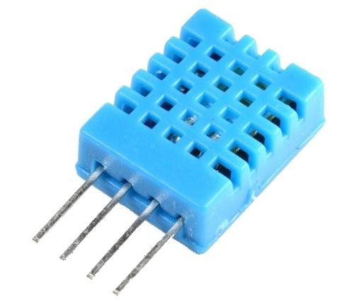
The DHT11 is a basic, ultra-low-cost digital temperature and humidity sensor. It uses a capacitive humidity sensor and a thermistor to measure the surrounding air and outputs a digital signal on the data pin. It’s simple to use but requires careful timing to grab data. It’s perfect for DIY projects, weather stations, and other applications where accurate and reliable temperature and humidity readings are needed.
Key Features:
- Temperature Range: 0-50°C with ±2°C accuracy
- Humidity Range: 20-80% RH with ±5% RH accuracy
- Low Power Consumption: Efficient for battery-operated applications
- Single Wire Digital Interface: Easy to interface with microcontrollers
- Pre-calibrated: No need for additional calibration
- Compact Size: Suitable for compact projects and devices
Technical Specifications:
- Temperature Range: 0-50°C (32-122°F)
- Humidity Range: 20-80% RH
- Temperature Accuracy: ±2°C
- Humidity Accuracy: ±5% RH
- Operating Voltage: 3.3V to 5.5V
- Max Current: 2.5mA
- Output: Digital signal via 1-wire protocol
- Dimensions: 15.5mm x 12mm x 5.5mm
Applications:
- Weather Stations: Monitor and log temperature and humidity levels.
- Home Automation: Control HVAC systems based on environmental conditions.
- Greenhouses: Maintain optimal growing conditions for plants.
- DIY Projects: Perfect for hobbyists building custom sensors and gadgets.
- Data Loggers: Record environmental data over time for analysis.
- Educational Projects: Teach students about sensors and data acquisition.
Usage:
- Wiring: Connect the VCC pin to 3.3V or 5V, GND to ground, and the DATA pin to a digital input on your microcontroller.
- Library Integration: Use libraries available for platforms like Arduino or Raspberry Pi to simplify reading data from the sensor.
- Coding: Write code to initialize the sensor and read temperature and humidity data.
- Data Processing: Process and use the sensor data in your application as needed, such as displaying it on an LCD or sending it to a web server.
Caution:
- Power Supply: Ensure the sensor is supplied with the correct voltage to avoid damage.
- Environmental Conditions: Keep the sensor in a dust-free, non-condensing environment for accurate readings.
- Wiring Length: Minimize the length of wiring between the sensor and the microcontroller to maintain signal integrity.
Datasheet:
For detailed technical specifications, refer to the DHT11 Datasheet.
|
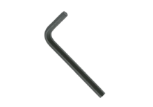
The Allen key, also known as a hex key or hex wrench, is a tool used to drive screws and bolts with hexagonal sockets. The Size 2 mm Allen key is designed for use with fasteners that have a 2 mm hexagonal socket. This size is commonly used in various precision and small-scale applications.
Key Features:
- Size: 2 mm (hexagonal socket size)
- Shape: Typically L-shaped or T-shaped
- Material: Often made from high-strength steel or chrome vanadium for durability
- Finish: Commonly coated with black oxide, chrome plating, or other protective finishes to resist corrosion
- Type: Available in different designs, such as short or long arm, and sometimes with a ball end for use at an angle
Technical Specifications:
- Hexagon Size: 2 mm
- Length: Varies by design, e.g., 40 mm to 100 mm for short arms, and longer for T-handle or L-handle versions
- Material: Steel, chrome vanadium, or other hardened materials
- Finish: Black oxide, chrome-plated, or other protective coatings
Applications:
- Precision Work: Ideal for tasks involving small screws and bolts, such as in electronics, small machinery, and model assembly.
- Model Building: Commonly used in assembling and repairing model kits and hobby projects.
- Bicycles: Useful for adjustments on bicycle components that require a small hex size.
- Electronics: Essential for assembling and servicing electronic devices with small hex screws.
- Furniture Assembly: Often used for small, precision parts in flat-pack furniture.
Datasheet:
Allen keys typically do not have detailed datasheets, but specifications can be obtained from the tool manufacturer or supplier.
|
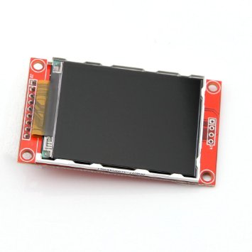
The 2.2-inch colored LCD is a compact display module designed to provide clear and vibrant visual output in a small form factor. This LCD module is ideal for various embedded applications where space is limited but a color display is required. It is commonly used in consumer electronics, handheld devices, and development projects.
Key Features:
- 2.2-inch TFT LCD display
- High-resolution color display for clear and vibrant visuals
- Wide viewing angle for better visibility from different perspectives
- Supports multiple color formats (RGB)
- Easy integration with microcontrollers and development boards
- Low power consumption for efficient operation
- Durable and compact design
Technical Specifications:
- Display Type: TFT LCD
- Screen Size: 2.2 inches
- Resolution: 240 x 320 pixels
- Color Depth: 65K colors (16-bit RGB)
- Interface: SPI, parallel (depends on model)
- Operating Voltage: 3.3V to 5V
- Backlight: LED
- Viewing Angle: 160° horizontal/vertical (varies by model)
- Dimensions: Varies by manufacturer (common size: 50mm x 60mm x 6mm)
- Weight: Varies by manufacturer (typically around 25g)
Applications:
- Portable electronic devices
- Handheld gadgets and consumer electronics
- Industrial control displays
- Educational projects and prototyping
- Home automation systems
Usage:
- Connect the LCD module to your microcontroller or development board using the appropriate interface (SPI, parallel).
- Power the module with a compatible power source (3.3V to 5V).
- Install and configure the necessary display libraries and drivers for your development environment.
- Use the provided functions to initialize the display and send data for visualization.
- Customize the display output according to your project requirements.
Caution:
- Handle the LCD module with care to avoid damage to the screen or connectors.
- Ensure correct wiring and voltage levels to prevent electrical damage.
- Follow the manufacturer’s guidelines for installation and operation to avoid damage and ensure proper functionality.
Datasheet:
For detailed technical specifications, refer to the 2.2-Inch Colored LCD Datasheet.
|
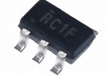
The LMV321IDBVR is a low power operational amplifier designed for general-purpose applications where low voltage, low power consumption, and small package size are critical.
Key Features:
- Supply Voltage: Typically operates from 2.7V to 5.5V.
- Low Quiescent Current: Helps in conserving power, suitable for battery-operated devices.
- Low Offset Voltage: Provides accurate amplification of small signals.
- Single Supply Operation: Suitable for applications with single power supply voltage.
- Rail-to-Rail Output: Capable of driving signals close to both supply rails.
- Small Package: Available in SOT-23-5 package, suitable for space-constrained applications.
Technical Specifications:
- Number of Channels: Single operational amplifier.
- Bandwidth: Typically ranges up to several MHz.
- Slew Rate: Provides fast response to input signals.
- Input Offset Voltage: Low input offset voltage for precision applications.
- Temperature Range: Typically operates from -40°C to +125°C.
- Applications: Ideal for battery-powered devices, sensor interfaces, signal conditioning, and portable electronics.
Datasheet:
For detailed technical information, refer to the LMV321IDBVR Datasheet.
|
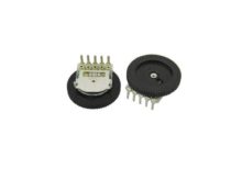
The 10k Single Gear Potentiometer is an adjustable resistor with a resistance range of 0 to 10 kΩ. It features a single gear mechanism for manual adjustment of resistance. This type of potentiometer is commonly used in various electronic circuits to control voltage, adjust signal levels, and fine-tune parameters.
Key Features:
- Resistance: 10 kΩ
- Type: Single gear (single-turn) potentiometer
- Adjustment Mechanism: Manual adjustment using a rotary knob
- Mounting Type: Typically through-hole or surface-mount
- Material: Usually made from conductive carbon or metal film
Technical Specifications:
- Resistance Range: 0 to 10 kΩ
- Tolerance: Typically ±10% or ±20% (depends on the model)
- Number of Turns: Single-turn (single gear)
- Maximum Power Rating: Usually up to 0.5W
- Temperature Coefficient: Varies by model, typically around ±100 ppm/°C
- Mounting Type: Through-hole or surface-mount (varies by design)
- Adjustment Type: Rotary knob or shaft
Applications:
- Volume Control: Used in audio equipment to adjust volume levels.
- Signal Adjustment: Ideal for fine-tuning signals in electronic circuits.
- Calibration: Useful for calibrating and setting parameters in various devices.
- Control Interfaces: Applied in user interfaces for controlling devices and systems.
- Prototyping: Commonly used in electronic prototypes and experimental setups.
Datasheet:
For detailed technical information, refer to the datasheet of the specific 10k single gear potentiometer model, as specifications can vary based on the manufacturer and design.
|
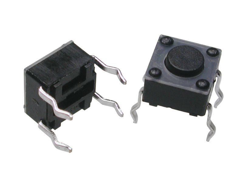
A Tact Switch, also known as a tactile switch, is a type of switch designed to provide a tactile feedback when pressed. These switches are commonly used in electronic devices for user input, such as in keyboards, remote controls, and various consumer electronics. Tact switches are known for their compact size, reliability, and ease of integration into circuits.
Key Features:
- Tactile Feedback: Provides a satisfying click feel when pressed.
- Compact Size: Small and suitable for space-constrained applications.
- Reliability: Durable and designed for a high number of actuation cycles.
- Variety of Sizes: Available in different sizes and heights to fit various designs.
- Easy Mounting: Can be mounted on PCBs with through-hole or surface-mount technology.
- Wide Application Range: Suitable for a variety of electronic devices and applications.
Technical Specifications:
- Contact Rating: Typically 50mA, 12V DC
- Contact Resistance: ≤ 100mΩ
- Insulation Resistance: ≥ 100MΩ at 100V DC
- Dielectric Strength: 250V AC for 1 minute
- Operating Force: Typically 160gf (varies by model)
- Travel: Typically 0.25mm to 0.5mm
- Operating Life: Typically 100,000 to 1,000,000 cycles
- Operating Temperature Range: -20°C to +70°C
Applications:
- Consumer Electronics: Used in remote controls, calculators, and gaming controllers.
- Computer Peripherals: Keyboards, mice, and other input devices.
- Home Appliances: Control panels for microwaves, washing machines, and other appliances.
- Automotive: Control buttons on car dashboards and steering wheels.
- Industrial Equipment: Control panels and user interfaces for machinery.
- DIY Projects: Suitable for custom electronic projects and prototypes.
Usage:
- Mounting: Solder the tact switch onto a PCB, ensuring correct alignment of the pins.
- Wiring: Connect the switch to your circuit, typically using pull-up or pull-down resistors.
- Testing: Verify the switch functionality by pressing it and checking the response in your circuit.
- Integration: Integrate the switch into your final product, ensuring it is accessible and functions as intended.
Caution:
- Debouncing: Implement debouncing in your software to ensure accurate readings.
- Proper Soldering: Avoid excessive heat during soldering to prevent damage to the switch.
- Environmental Conditions: Ensure the switch is used within its specified temperature and humidity range.
Datasheet:
For detailed technical specifications, refer to the Tact Switch Datasheet.
|
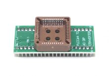
The PLC44 to DIP40 IC Socket Adapter is designed to convert a 44-pin PLCC (Plastic Leaded Chip Carrier) IC package into a 40-pin DIP (Dual Inline Package) socket configuration. This adapter enables the use of PLCC ICs in DIP socket-compatible PCBs and prototyping setups, simplifying integration and testing.
Key Features:
- Convenient Conversion: Adapts a 44-pin PLCC IC for use with a 40-pin DIP socket.
- High-Quality Construction: Built with durable materials to ensure reliable connections and longevity.
- Gold-Plated Contacts: Provides excellent conductivity and corrosion resistance.
- Compact Form Factor: Suitable for use with standard breadboards and PCB mountings.
- Easy Installation: Allows for quick and straightforward installation and removal of ICs.
Technical Specifications:
- Package Type: PLC44 to DIP40
- Pin Pitch (PLCC): 1.27mm
- Pin Pitch (DIP): 2.54mm
- Material: FR4 PCB, Gold-plated contacts
- Dimensions: Varies by model
- Weight: Lightweight design
- Temperature Range: -40°C to +85°C
- Mounting Type: Through-hole
Applications:
- Prototyping: Enables the use of PLCC ICs on DIP-compatible breadboards and prototype boards.
- Development: Facilitates the integration of PLCC devices into DIP-based circuit designs.
- Repair and Replacement: Useful for adapting PLCC ICs in existing DIP-based systems or repairs.
- Educational Use: Ideal for demonstrating the use and conversion of different IC package types.
|
The Push and Hold Switch is a type of momentary switch designed to activate a circuit only while it is being pressed. This switch maintains its contact state as long as the user continues to hold it down, and returns to its default position once released. It is commonly used in applications where continuous activation is needed for a function, such as in temporary control circuits, safety devices, and interactive electronics.
Key Features:
- Momentary action: activates only while held down
- Provides tactile feedback for user confirmation
- Available in various sizes and mounting styles
- Reliable and durable for repeated use
- Can be used for both AC and DC applications
- Simple installation with clear actuation feedback
Technical Specifications:
- Type: Momentary (normally open)
- Actuation Force: Varies by model (typically between 100g and 300g)
- Contact Rating: Typically 1A at 12V DC or 0.5A at 250V AC (check specific model)
- Contact Resistance: <50Ω
- Insulation Resistance: >100MΩ at 250V DC
- Dielectric Strength: 500V AC for 1 minute
- Operating Temperature Range: -20°C to +70°C
- Mounting Style: Panel mount, surface mount, or through-hole (varies by model)
Applications:
- Temporary control functions in electronic devices
- Safety switches in machinery
- Interactive user interfaces
- Alarm systems and emergency controls
- Testing and calibration equipment
Usage:
- Mount the Push and Hold Switch on the desired panel or enclosure using the appropriate mounting method.
- Connect the switch terminals to the control circuit, ensuring proper alignment and connection.
- Test the switch to verify that it activates the circuit only while held down and returns to its default state when released.
- Ensure the switch is securely mounted and properly insulated to avoid accidental activation or short circuits.
Caution:
- Avoid applying excessive force that might damage the switch or its mounting.
- Ensure correct voltage and current ratings for the specific application to prevent overheating or damage.
- Handle the switch carefully to avoid physical damage or degradation of the internal components.
Datasheet:
For detailed technical specifications, refer to the Push and Hold Switch Datasheet.
|
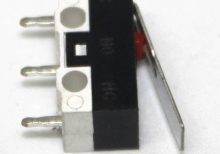
The 3-Pin Long Lever Micro Limit Switch is a compact, precision switch designed to detect the position of moving parts in various mechanical and electronic applications. It features a long lever arm that provides extended reach and precise actuation. This type of switch is commonly used in automation, robotics, and control systems to detect the limits or positions of moving components.
Key Features:
- Lever Type: Long lever arm for extended reach
- Pins: 3-pin configuration for easy connection
- Actuation Type: Mechanical, with a tactile click when actuated
- Compact Size: Designed for small spaces and easy integration
- Durability: Built to handle a high number of actuations
- Precision: Provides accurate position detection
Technical Specifications:
- Dimensions:
- Lever Length: Varies, typically around 40 mm to 60 mm
- Body Size: Approximately 15 mm x 10 mm x 10 mm
- Actuation Force: Typically around 200-300 g (varies by model)
- Contact Rating:
- Voltage: Up to 125V AC or 30V DC (typical)
- Current: 5A (typical)
- Contact Resistance: Typically 50 mΩ or less
- Insulation Resistance: Typically 100 MΩ or more
- Durability: Up to 1,000,000 cycles (varies by manufacturer)
- Operating Temperature: -10°C to +60°C
Applications:
- Automation: Used in automated systems to detect the end position or limits of moving parts.
- Robotics: Ideal for robots and automated machinery to ensure correct positioning.
- Control Systems: Employed in control panels and equipment to signal limit conditions.
- Consumer Electronics: Can be used in devices requiring precise position detection.
Datasheet:
For detailed technical information, refer to the 3-Pin Long Lever Micro Limit Switch Datasheet.
|
The 12V Mini Waterproof Pump is a compact, high-efficiency pump designed for a variety of applications requiring water movement or transfer. It is waterproof, allowing it to be used in submerged or wet environments. Its small size and robust performance make it ideal for use in aquariums, small fountains, cooling systems, and portable water systems.
Key Features:
- Compact and space-efficient
- Waterproof and suitable for submersible use
- High flow rate with low power consumption
- Durable construction with long service life
- Quiet operation
Technical Specifications:
- Operating Voltage: 12V DC
- Flow Rate: 180-250 liters per hour (L/h)
- Maximum Head (Lift): 1.5m to 2m
- Power Consumption: 4-6W
- Operating Temperature Range: 0°C to +60°C
- Dimensions: 60mm x 40mm x 40mm (length x width x height, approximate)
- Weight: 90g
- Inlet/Outlet Size: 6mm (barbed connectors)
- Material: Plastic body, rubber seals
Applications:
- Aquariums: Ideal for water circulation and filtration.
- Fountains: Suitable for small decorative water features and fountains.
- Portable Water Systems: Useful in camping, boating, and portable water transfer applications.
- Hydroponics: Employed in hydroponic systems for circulating nutrient solutions.
- Cooling Systems: Applied in small electronic cooling and machinery cooling systems.
Datasheet:
For detailed technical information, refer to the 12V Mini Waterproof Pump Datasheet provided by the manufacturer.
|
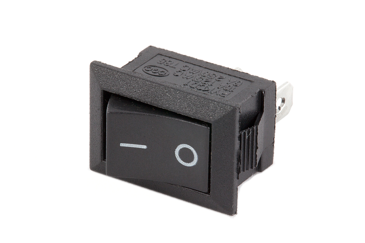
A switch is an electrical component used to make or break a connection in an electrical circuit. It allows the user to control the flow of electricity by toggling between an open (off) and closed (on) position. Switches are essential components in various applications, from household appliances to industrial machinery.
Key Features:
- Function: Controls the flow of electrical current
- Types: Available in various types, including toggle, push-button, rocker, slide, and rotary
- Design: Can be designed for single or multiple circuits
- Mounting Options: Options include panel-mount, surface-mount, and through-hole
Technical Specifications:
- Type: Varies by application (e.g., toggle, push-button, rocker, slide, rotary)
- Contact Rating: Typically specified in voltage and current ratings (e.g., 250V AC, 10A)
- Mechanical Life: Number of cycles the switch can handle before failure (e.g., 1,000,000 cycles)
- Electrical Life: Number of cycles the switch can handle under load (e.g., 100,000 cycles)
- Mounting Type: Can be panel-mount, surface-mount, or through-hole
- Actuation Force: Force required to operate the switch (e.g., 1-5N)
- Insulation Resistance: Resistance to electrical leakage (e.g., >100MΩ)
Applications:
- Household Appliances: Control of lights, fans, and other devices
- Industrial Equipment: Machinery and control panels
- Automotive: Control functions in vehicles
- Consumer Electronics: Power and function controls in gadgets
- Computers: Power buttons and user interface controls
Usage:
- Mounting: Install the switch according to its mounting type.
- Wiring: Connect the switch to the electrical circuit as per its contact ratings.
- Operation: Toggle, push, or slide the switch to control the flow of electricity.
Caution:
- Voltage and Current Ratings: Ensure the switch is rated for the voltage and current of your application to prevent overheating and failure.
- Proper Mounting: Securely mount the switch to avoid mechanical damage.
- Handling: Avoid applying excessive force or impact to prevent damage.
|
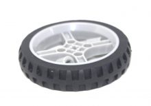
The 65mm Smart Car Tyre Narrow Wheel is designed for use in small robotics and smart car projects. These wheels provide excellent traction and durability, making them ideal for navigating various surfaces. Their narrow design allows for precise control and maneuverability, which is essential for robotics applications.
Key Features:
- Size: 65mm diameter, narrow width for precise control
- Durable Material: Made from high-quality rubber for enhanced durability and grip
- Easy Installation: Compatible with standard smart car and robot axles
- Smooth Performance: Ensures stable and smooth movement on various surfaces
- Lightweight: Lightweight construction for efficient energy use in small robotic projects
Technical Specifications:
- Diameter: 65mm
- Width: 8mm
- Material: High-quality rubber with plastic hub
- Axle Hole Diameter: 3mm
- Weight: 15g per wheel
- Color: Black
Applications:
- Smart Car Projects: Ideal for DIY smart car kits and educational robotics
- Robotics Competitions: Suitable for robotics competitions requiring precise control
- Line Following Robots: Enhances the performance of line-following robots
- Obstacle Avoidance Robots: Provides reliable movement for obstacle avoidance tasks
- Prototyping: Useful in various prototyping and small-scale robotics projects
|
The Reset Button/Switch is designed to restore a device or system to its initial state by interrupting power or resetting internal circuits when pressed. It is commonly used in electronic devices, computers, and industrial machinery to quickly restart or clear errors without requiring a full shutdown. The button is typically a momentary switch that returns to its default position once released.
Key Features:
- Momentary action: activates only while pressed
- Provides a reliable method for resetting devices or systems
- Available in various sizes, mounting styles, and actuation forces
- Clear tactile feedback to confirm activation
- Often includes a visual indicator (e.g., red color) for easy identification
- Suitable for both AC and DC applications
Technical Specifications:
- Type: Momentary (normally open or normally closed)
- Actuation Force: Varies by model (typically between 100g and 300g)
- Contact Rating: Typically 1A at 12V DC or 0.5A at 250V AC (check specific model)
- Contact Resistance: <50Ω
- Insulation Resistance: >100MΩ at 250V DC
- Dielectric Strength: 500V AC for 1 minute
- Operating Temperature Range: -20°C to +70°C
- Mounting Style: Panel mount, surface mount, or through-hole (varies by model)
Applications:
- Computer systems (e.g., to reset a computer or microcontroller)
- Electronic devices (e.g., to clear errors or restart operations)
- Industrial control panels (e.g., to reset machinery or processes)
- Consumer electronics (e.g., appliances, gadgets)
- Automotive applications (e.g., to reset onboard systems)
Usage:
- Mount the Reset Button/Switch on the desired panel or enclosure using the appropriate mounting method.
- Connect the switch terminals to the reset circuitry or control system.
- Test the button to ensure it properly resets the device or system when pressed and released.
- Ensure the switch is securely mounted and easily accessible for users.
Caution:
- Ensure the button is properly rated for the voltage and current of the application to avoid damage.
- Handle with care to avoid physical damage to the switch or its contacts.
- Verify correct wiring and connections to prevent malfunction or short circuits.
Datasheet:
For detailed technical specifications, refer to the Reset Button/Switch Datasheet.
|
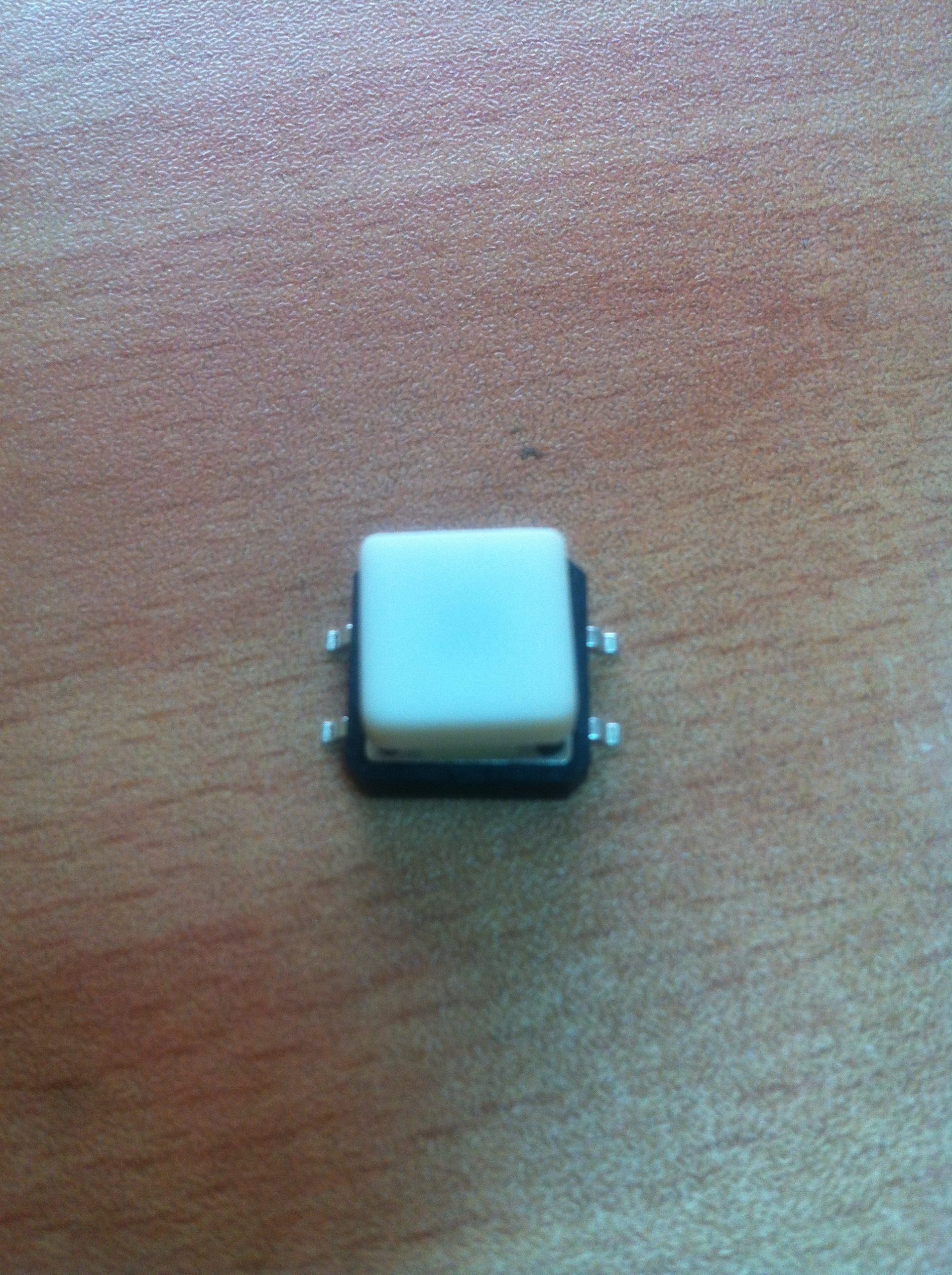
The SMD (Surface-Mount Device) tact switch with cap is a compact, reliable switch used in various electronic devices and applications. The switch is mounted directly onto a printed circuit board (PCB) and is designed to be activated by pressing the cap. The cap provides a user-friendly interface and helps in guiding the pressing action.
Key Features:
- Type: SMD Tactile Switch
- With Cap: Includes a cap for easy pressing and improved tactile feedback
- Mounting Type: Surface-mount for easy PCB integration
- Actuation Force: Typically designed for low actuation force
- Switch Function: Momentary contact (normally open; closes when pressed)
- Durability: Designed for many cycles of operation
Technical Specifications:
- Package Type: SMD (Surface-Mount Device)
- Cap Type: Plastic or rubber cap for tactile feedback
- Actuation Force: Typically ranges from 100g to 500g (varies by model)
- Contact Rating: Generally rated for 50mA to 100mA at 12V (varies by model)
- Contact Resistance: Typically 100Ω or less
- Insulation Resistance: Typically 100MΩ or more
- Life Cycle: Rated for up to 1,000,000 cycles
- Operating Temperature Range: -20°C to +85°C
Applications:
- Consumer Electronics: Used in devices like remote controls, calculators, and handheld devices
- Industrial Equipment: Integrated into control panels and user interfaces
- Automotive: Utilized in dashboards and control systems
- Medical Devices: Employed in compact medical equipment and interfaces
Usage:
- PCB Mounting: Solder the SMD tact switch to the designated pads on the PCB.
- Cap Placement: Ensure the cap is securely placed on the switch for proper operation and tactile feedback.
- Testing: Test the switch to ensure it functions correctly and provides the desired tactile response.
- Integration: Integrate the switch into the final assembly and connect it to the necessary circuits or components.
Caution:
- Handling: Handle with care to avoid damaging the switch or cap.
- Soldering: Follow proper soldering techniques to avoid overheating or damaging the switch.
- Compatibility: Ensure the switch is compatible with the design requirements and PCB layout.
Datasheet:
For detailed technical specifications and mounting guidelines, refer to the manufacturer’s datasheet for the specific SMD tact switch model.
|
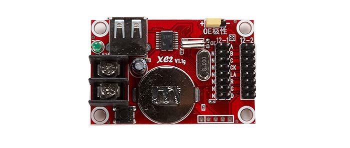
The XC2 is a versatile and high-performance integrated circuit (IC) designed for specific applications in electronic systems. While the specific functionality and details can vary depending on the exact model and manufacturer, the XC2 series typically includes features such as advanced processing capabilities, flexible I/O options, and support for a range of communication protocols. This series is used in various applications requiring efficient data handling, control, and signal processing.
Key Features:
- High-speed processing capabilities
- Flexible I/O options
- Support for multiple communication protocols
- Low power consumption
- Reliable performance in demanding environments
- Available in various package types
Technical Specifications:
- Package Type: Varies by model (e.g., TQFP, BGA)
- Operating Voltage: Typically 3.3V or 5V (depends on specific model)
- Clock Speed: Varies by model
- Memory: Varies by model (e.g., Flash, SRAM)
- I/O Pins: Varies by model
- Communication Interfaces: UART, SPI, I2C, etc. (depends on specific model)
- Operating Temperature Range: Varies by model
Applications:
- Embedded systems
- Industrial automation
- Consumer electronics
- Communication devices
- Automotive control systems
- Medical devices
Usage:
- Program the XC2 IC using the appropriate programming tools and software.
- Connect external peripherals and components to the IC’s I/O pins as required by your application.
- Configure the IC’s settings and features through software or hardware interfaces.
- Integrate the IC into your circuit and ensure proper functionality through testing.
Caution:
- Check the specific datasheet for detailed specifications and handling instructions for the XC2 model you are using.
- Ensure compatibility with your circuit’s voltage and current requirements.
- Handle with care to avoid damage from electrostatic discharge (ESD).
|
|
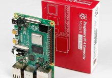
The Raspberry Pi 4 Model B is a versatile and powerful single-board computer, designed for a wide range of applications from DIY projects to professional development. The 1GB RAM version offers sufficient memory for basic tasks and lightweight applications, making it an ideal choice for various computing needs.
Key Features:
- Powerful Processor: Quad-core ARM Cortex-A72 CPU running at 1.5 GHz
- Memory: 1GB LPDDR4 RAM
- Connectivity: Gigabit Ethernet, 2.4GHz and 5GHz Wi-Fi, Bluetooth 5.0
- USB Ports: 2x USB 3.0, 2x USB 2.0
- Video Output: 2x Micro HDMI ports (up to 4K resolution)
- Storage: MicroSD card slot
- GPIO: 40-pin GPIO header for expansion and interfacing
Technical Specifications:
- Processor: Quad-core ARM Cortex-A72, 1.5 GHz
- Memory: 1GB LPDDR4
- Networking: Gigabit Ethernet, Wi-Fi 802.11ac, Bluetooth 5.0
- USB Ports: 2x USB 3.0, 2x USB 2.0
- Video Output: 2x Micro HDMI (supports up to 4K resolution)
- Audio: 3.5mm audio jack
- Storage: MicroSD card slot
- GPIO: 40-pin GPIO header
- Power Supply: 5V DC via USB-C
- Dimensions: 85.6 mm x 56.5 mm
Applications:
- Personal Computers
- Media Centers
- Educational Tools
- Home Automation
- IoT Projects
Usage:
- Connect the Raspberry Pi 4 to a monitor via Micro HDMI cables.
- Insert a microSD card with the desired operating system.
- Connect a USB keyboard and mouse.
- Power the board using a 5V USB-C power supply.
- Follow on-screen instructions to set up the operating system.
Caution:
- Use a compatible 5V USB-C power supply to avoid power issues.
- Handle the board with care to avoid damage to connectors and components.
Datasheet:
For more detailed technical information, refer to the Raspberry Pi 4 Model B Datasheet.
|
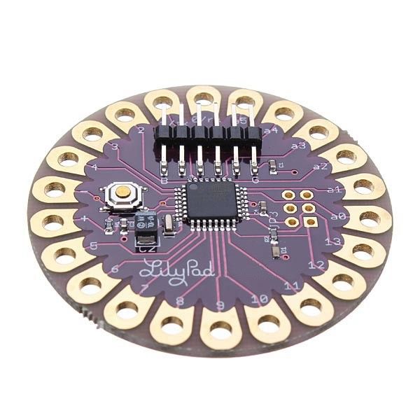
The Arduino LilyPad is a flexible and washable microcontroller board designed for e-textiles and wearable electronics. It is part of the Arduino platform and features a unique design that allows it to be integrated into fabric and clothing. The LilyPad is ideal for projects that require electronic components to be embedded in textiles, enabling creative and interactive wearable technology.
Key Features:
- Microcontroller: ATmega328P, similar to Arduino Uno
- Flexible Design: Can be sewn into fabric or clothing
- Washable: Water-resistant design for washable applications (note: always check the specific model’s washing instructions)
- Connectivity: Includes a range of I/O pins for connecting sensors, actuators, and other components
- Power Supply: Can be powered via USB or external battery pack
- Programming: Compatible with the Arduino IDE for easy programming
Technical Specifications:
- Dimensions:
- Weight: Approximately 10 g
- Operating Voltage: 2.7V to 5.5V DC
- Digital I/O Pins: 14 (of which 6 provide PWM output)
- Analog Input Pins: 6
- Flash Memory: 32 KB (ATmega328P) of which 0.5 KB used by bootloader
- SRAM: 2 KB (ATmega328P)
- EEPROM: 1 KB (ATmega328P)
- Clock Speed: 16 MHz
- Communication: UART, SPI, I2C
- Power Supply: Can be powered via USB or battery (battery not included)
- Connector Types: Sewable conductive thread or wire for connections
Applications:
- Wearable Technology: Ideal for creating interactive clothing and accessories.
- E-Textiles: Used in smart fabrics and textiles for embedded electronics.
- Education: Useful for teaching electronics and programming in a hands-on manner.
- DIY Projects: Perfect for hobbyists creating custom wearable gadgets.
- Interactive Art: Enables the creation of art installations that involve electronics and textiles.
Datasheet:
For detailed technical information, refer to the Arduino LilyPad Datasheet.
|
