|
Description |
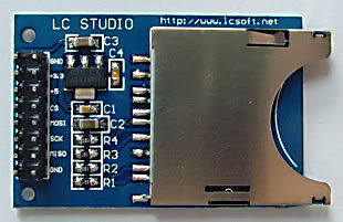
The SD Card Module is a compact and efficient solution for adding storage capabilities to your microcontroller or development board projects. It allows you to read from and write to SD cards, making it ideal for data logging, file storage, and other applications requiring large amounts of memory. The module supports various SD card formats and interfaces seamlessly with popular microcontrollers like Arduino, Raspberry Pi, and others.
Key Features:
- Storage: Supports SD, SDHC, and MicroSD (with adapter) cards
- Interface: SPI interface for easy integration
- Voltage Compatibility: Operates at 3.3V and 5V
- Onboard 3.3V Regulator: Ensures stable operation
- Card Detection: Built-in card detection switch
- Compact Design: Small footprint for easy incorporation into projects
- File System: Compatible with FAT16 and FAT32 file systems
Technical Specifications:
- Supported Cards: SD, SDHC, MicroSD (with adapter)
- Operating Voltage: 3.3V/5V
- Interface: SPI
- Current Consumption: < 100mA
- File System: FAT16, FAT32
- Dimensions: 42mm x 24mm x 12mm
Applications:
- Data Logging: Store sensor data and logs in embedded systems.
- File Storage: Save files for multimedia applications and projects.
- Firmware Updates: Load new firmware from the SD card for microcontrollers.
- DIY Projects: Perfect for hobbyists needing additional storage.
- Educational Projects: Commonly used in learning modules for data storage and retrieval.
Usage:
- Wiring: Connect the SD card module to your microcontroller using the SPI interface (CS, MOSI, MISO, SCK, VCC, GND).
- Power Supply: Ensure the module is powered with 3.3V or 5V, as required.
- Card Insertion: Insert a formatted SD card into the module.
- Programming: Use libraries (e.g., SD library for Arduino) to initialize the SD card and read/write data.
- Data Handling: Store or retrieve data files from the SD card as needed by your application.
Caution:
- Voltage Levels: Ensure proper voltage levels to avoid damaging the module.
- Handling SD Cards: Handle SD cards with care to prevent data loss or corruption.
Datasheet:
For detailed technical specifications, refer to the SD Card Module Datasheet.
|
The Arduino USB Host Shield enables the connection of USB devices to an Arduino board, expanding its functionality by allowing it to interface with USB peripherals. Based on the MAX3421E USB controller, this shield supports full-speed USB operation and is compliant with USB specification 2.0. It is ideal for projects that require interaction with USB devices such as keyboards, mice, or storage devices.
Key Features:
- Connects USB devices to Arduino boards
- Based on the MAX3421E USB controller (datasheet)
- Supports full-speed USB operation
- Compatible with a variety of USB peripherals
Technical Specifications:
- Operating Voltage: 5V
- USB Controller: MAX3421E
- Maximum Current: 500mA (when Arduino is powered by an external power supply)
- Maximum Current: 400mA (when Arduino is powered via USB)
Applications:
- Connecting USB devices (keyboards, mice) to Arduino
- USB data logging and communication
- Building USB-controlled projects
Usage:
- Mount the USB Host Shield on the Arduino board.
- Connect the USB device to the shield’s USB port.
- Use the Arduino USB Host library to interface with the USB device.
- Develop and upload the necessary Arduino sketch for device interaction.
Caution:
- Ensure that the Arduino power source is sufficient to provide the required current for connected USB devices.
- Verify compatibility of connected USB devices with the shield.
- Follow manufacturer guidelines for proper installation and use.
Datasheet:
For detailed technical specifications, refer to the MAX3421E Datasheet.
|
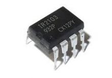
The IR2103PBF is a high voltage, high-speed power MOSFET and IGBT driver with independent high and low side referenced output channels. It is designed to drive high-side and low-side N-channel power MOSFETs or IGBTs in a half-bridge configuration. The device features a floating channel designed for bootstrap operation, allowing it to drive the high-side switch up to 600V.
Key Features:
- Gate drive supply range from 10V to 20V
- Floating channel can be used to drive an N-channel power MOSFET or IGBT in the high-side configuration up to 600V
- Gate drive outputs: 2A peak source, 2A peak sink
- Independent high-side and low-side channels
- Under-voltage lockout for both channels
- Logic input (IR2103) compatible with standard CMOS or LSTTL outputs
- Matched propagation delay for both channels
- Low side output in phase with input signal
- High side output out of phase with input signal
Technical Specifications:
- Supply Voltage (Vcc): 10V – 20V
- Floating Supply Voltage (Vb): up to 600V
- Logic Supply Voltage (Vss): -5V – 20V
- Output Source Current (Io+): 2A
- Output Sink Current (Io-): 2A
- Gate Drive Output Voltage (Vout): 10V – 20V
- Propagation Delay: 120ns (typical)
- Operating Temperature Range: -40°C to +125°C
- Package: PDIP-8
Applications:
- Motor drive applications
- Induction heating
- UPS systems
- DC-DC converters
- Switch-mode power supplies
Datasheet:
For detailed technical information, please refer to the IR2103PBF Datasheet.
|
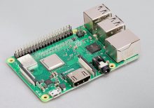
The Raspberry Pi 3B+ is a powerful, compact computer designed for a wide range of applications, from educational projects to complex industrial use. It features a quad-core ARM Cortex-A53 CPU, enhanced network capabilities, and various connectivity options, making it versatile and efficient for multiple tasks.
Key Features:
- High-Performance Processor: Quad-core ARM Cortex-A53, 1.4GHz
- Networking: Dual-band 2.4GHz and 5GHz IEEE 802.11.b/g/n/ac wireless LAN, Bluetooth 4.2, BLE, Gigabit Ethernet over USB 2.0 (maximum throughput 300 Mbps)
- Memory: 1GB LPDDR2 SDRAM
- USB Ports: 4x USB 2.0 ports
- Video Output: Full-size HDMI
- Audio Output: 4-pole stereo output and composite video port
- Storage: MicroSD card slot for loading operating system and data storage
- Power Supply: 5V/2.5A DC via micro USB connector
Technical Specifications:
- Processor: Broadcom BCM2837B0, Cortex-A53 (ARMv8) 64-bit SoC @ 1.4GHz
- Memory: 1GB LPDDR2 SDRAM
- Networking:
- 2.4GHz and 5GHz IEEE 802.11.b/g/n/ac wireless LAN
- Bluetooth 4.2, BLE
- Gigabit Ethernet over USB 2.0 (maximum throughput 300 Mbps)
- USB Ports: 4x USB 2.0
- Video Output: Full-size HDMI
- Audio Output: 4-pole stereo output and composite video port
- Storage: MicroSD
- Power Supply: 5V/2.5A DC via micro USB connector
Applications:
- Educational projects and learning platforms
- Home automation systems
- Media centers
- DIY electronics and prototyping
- Industrial control systems
Usage:
- Insert a microSD card with a pre-installed operating system into the microSD card slot.
- Connect the Raspberry Pi 3B+ to a display using the HDMI port.
- Connect a keyboard and mouse to the USB ports.
- Plug in the power supply to the micro USB connector.
- Follow the on-screen instructions to complete the setup process.
Caution:
- Use a compatible power supply to avoid damaging the board.
- Handle the board with care to prevent static discharge and damage to components.
- Avoid exposure to moisture and extreme temperatures.
Datasheet: For more detailed technical information, refer to the Raspberry Pi 3B+ Datasheet.
|


