|
Description |
A small size dotted Vero board, also known as a stripboard or prototyping board, is a type of circuit board that is used for prototyping and building electronic circuits. It features a grid of holes with copper pads that allow components to be easily soldered onto the board. The dotted pattern provides flexibility in layout, making it ideal for custom circuit designs and small electronic projects.
Key Features:
- Dotted pattern for versatile circuit layout
- High-quality FR4 material for durability
- Copper pads for easy soldering
- Small size for compact projects
- Compatible with through-hole components
- Suitable for prototyping and custom circuit building
Technical Specifications:
- Material: FR4 (fiberglass epoxy laminate)
- Size: Typically around 70mm x 90mm (varies by manufacturer)
- Hole Pitch: 2.54mm (standard 0.1 inch grid)
- Hole Diameter: 1.0mm (suitable for most through-hole components)
- Thickness: 1.6mm
- Copper Thickness: 35µm (1oz/ft²)
- Pattern: Dotted (individual copper pads)
- Number of Holes: Varies by board size (e.g., 25×35 grid for 70mm x 90mm board)
Applications:
- Prototyping electronic circuits
- Custom circuit design
- DIY electronics projects
- Educational and learning purposes
- Small-scale production of custom circuits
Usage:
- Design the Circuit:
- Plan the layout of your components and connections on the Vero board.
- Place the Components:
- Insert the components into the holes according to your circuit design.
- Solder the Components:
- Solder the component leads to the copper pads on the reverse side of the board.
- Create Connections:
- Use solder bridges or wire links to create electrical connections between the copper pads as needed.
- Test the Circuit:
- Verify the circuit functionality and make any necessary adjustments or corrections.
Caution:
- Ensure proper soldering techniques to avoid short circuits or poor connections.
- Handle the board carefully to avoid damaging the copper pads or FR4 material.
- Verify the component placement and connections before powering the circuit.
|
Description:
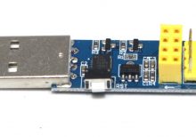
The ESP LINK V1.0 ESP8266-01 WiFi download module is a versatile device designed for programming and downloading firmware to ESP8266-01 modules. It simplifies the process of updating firmware and configuring settings for ESP8266-based projects.
Key Features:
- ESP8266-01 Compatibility: Specifically designed for use with ESP8266-01 modules.
- WiFi Connectivity: Provides a reliable connection for downloading and updating firmware.
- USB Interface: Connects to a computer via USB for easy programming and configuration.
- Support for Various Firmware: Compatible with a range of firmware for ESP8266-01 modules.
- Compact Design: Small footprint for easy integration into development setups.
- User-Friendly: Simplifies the process of flashing firmware and configuring ESP8266 modules.
Technical Specifications:
- Module: ESP LINK V1.0
- Compatible Chip: ESP8266-01
- Interface: USB
- Power Supply: 5V DC via USB
- Operating Temperature: Typically -40°C to +85°C
Applications:
- Firmware Programming: Ideal for flashing and updating firmware on ESP8266-01 modules.
- Development and Testing: Useful for developers working with ESP8266-based projects.
- Configuration: Facilitates the configuration of ESP8266 modules for various applications.
Datasheet:
For detailed technical information and specifications, please refer to the ESP LINK V1.0 ESP8266-01 WiFi Download Module Datasheet.
|
The ACS712 is a current sensor from Allegro Microsystems designed to measure current with a maximum rating of 30A. It provides an analog output voltage that is proportional to the current flowing through the sensor. The ACS712 is widely used in power monitoring, load current measurement, and over-current protection applications due to its high accuracy and ease of integration with microcontrollers and other electronic systems.
Key Features:
- Measures AC and DC current up to 30A
- Provides an analog output voltage proportional to the current
- High accuracy with low offset and temperature drift
- Integrated Hall effect sensor for non-invasive current measurement
- Small size and easy to integrate into various circuits
- On-chip signal conditioning and protection
Technical Specifications:
- Sensor Type: Hall Effect Current Sensor
- Current Range: ±30A (AC or DC)
- Output Voltage Range: Typically 0V to Vcc
- Sensitivity: 66mV/A (typical)
- Operating Voltage: 5V ±5%
- Zero Current Offset Voltage: Vcc/2 (typical)
- Temperature Range: -40°C to +85°C
- Current Measurement Accuracy: ±1.5% of full-scale current (typical)
- Package Type: SOP-8 or similar
Applications:
- Power monitoring and control
- Over-current protection systems
- Load current measurement in power supplies
- Motor current sensing
- Energy monitoring and management
Usage:
- Connect the ACS712 sensor to your microcontroller or development board, ensuring correct connection of the power supply (Vcc, GND) and the output voltage pin.
- Route the current-carrying conductor through the sensor to measure the current.
- Read the analog output voltage, which is proportional to the current, and process it according to your application needs.
- Calibrate the sensor if necessary to ensure accurate current measurement.
Caution:
- Ensure the current flowing through the sensor does not exceed the maximum rating (30A) to avoid damage.
- Properly insulate and protect the sensor and connections to prevent short circuits and ensure safe operation.
- Verify the power supply voltage and connections to avoid incorrect readings or sensor damage.
Datasheet:
For detailed technical specifications, refer to the ACS712 Datasheet.
|
The USBISP USBASP AVR Programmer is a versatile and compact device designed for programming AVR microcontrollers via a USB interface. It is commonly used in electronics development and prototyping for uploading firmware and software to AVR-based microcontroller boards. The programmer is compatible with a wide range of AVR microcontrollers and supports various programming modes and protocols.
Key Features:
- USB interface for easy connection to a computer
- Supports a wide range of AVR microcontrollers
- Compatible with popular programming software such as AVRDUDE
- Provides reliable and fast programming
- Compact and portable design
- Firmware upgradeable for added functionality
Technical Specifications:
- Interface: USB 2.0
- Supported Microcontrollers: ATtiny series, ATmega series, and other AVR microcontrollers
- Programming Voltage: 5V (can be powered via USB or external supply)
- Programming Modes: ISP (In-System Programming), HVSP (High-Voltage Serial Programming)
- Operating Temperature Range: 0°C to 70°C
- Dimensions: Approximately 50mm x 30mm x 10mm (may vary slightly by manufacturer)
- Weight: Approximately 20g
Applications:
- Firmware Uploading: Ideal for uploading firmware and software to AVR microcontrollers.
- Prototyping: Used in electronics development and prototyping for AVR-based projects.
- Development: Facilitates development and debugging of AVR microcontroller-based applications.
- Educational: Suitable for educational purposes and learning about microcontroller programming.
Usage:
- Connect the USBISP USBASP programmer to your computer via the USB port.
- Attach the programmer to the target AVR microcontroller using the appropriate ISP connector.
- Open compatible programming software (e.g., AVRDUDE) on your computer.
- Configure the software settings for your specific microcontroller and programming requirements.
- Upload the firmware or software to the microcontroller and verify the programming status.
Caution:
- Ensure proper connection to avoid damage to the microcontroller or programmer.
- Use the correct programming voltage and settings to prevent malfunction.
- Handle the programmer with care to avoid physical damage.
Datasheet:
For detailed technical specifications, refer to the USBISP USBASP AVR Programmer Datasheet.
|
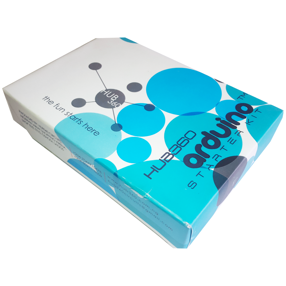
The Hub360 Arduino Starter Kit is a comprehensive package designed for beginners and enthusiasts looking to dive into the world of electronics and programming. This kit includes Arduino Uno, which is a microcontroller board based on the ATmega328P. The kit provides a variety of components and modules to help users learn and experiment with different electronic projects and concepts.
Key Features:
- Includes Arduino Uno board
- Comprehensive set of components and modules for various projects
- Ideal for beginners and hobbyists
- Detailed tutorial and project guide included
- USB interface for easy programming and power
- Compatible with Arduino IDE and various libraries
Technical Specifications:
- Microcontroller: ATmega328P
- Operating Voltage: 5V
- Input Voltage (recommended): 7-12V
- Digital I/O Pins: 14 (6 PWM outputs)
- Analog Input Pins: 6
- DC Current per I/O Pin: 20mA
- Flash Memory: 32KB (ATmega328P) of which 0.5KB used by bootloader
- SRAM: 2KB (ATmega328P)
- EEPROM: 1KB (ATmega328P)
- Clock Speed: 16 MHz
Kit Contents:
- ARDUINO BOARD 1
- ARDUINO USB CABLE 1
- ARDUINO BATTERY CONNECTOR 1
- 400 HOLE BREADBOARD 1
- LED (RED, YELLOW , GREEN, WHITE) 20
- RGB LED 1
- JUMPER WIRE(M-M, M-F, F-F) 120
- PHOTORESISTOR (LDR) 3
- MALE HEADERS 40
- ULTRASONIC SENSOR 1
- FLAME SENSOR 1
- TEMP./HUMIDITY SENSOR 1
- TILT SENSOR 1
- LASER SENSOR 1
- PIR MOTION SENSOR 1
- RESISTORS(220K, 1K, 10K,100K) 40
- 7 SEGMENT DISPLAY 1
- SG90 SERVO 1
- REMOTE CONTROL 1
- BUZZER 1
- 2N2222 2
- TSOP 1838 1
- RF TRANSMITTER 1
- RF RECEIVER 1
- TACT SWITCH 5
- 16*2 LCD DISPLAY
Applications:
- Learning basic electronics and programming
- Building interactive projects and prototypes
- Developing skills in microcontroller-based design
- Experimenting with sensors and actuators
- Creating DIY electronic devices
Usage:
- Setup:
- Connect the Arduino Uno board to your computer using the USB cable.
- Install the Arduino IDE and configure it to recognize the board.
- Programming:
- Write or upload sample code (sketches) to the Arduino board using the Arduino IDE.
- Utilize the provided components and modules to build and test different circuits.
- Experimentation:
- Follow the detailed tutorials and project guide to create various projects.
- Modify and expand on the sample projects to enhance learning and creativity.
Caution:
- Handle the components carefully to avoid damage.
- Ensure proper connections and polarity to prevent short circuits or component failure.
- Verify the code and circuit connections before powering the board.
Datasheet:
For detailed technical specifications of the Arduino Uno, refer to the Arduino Uno Datasheet.
|
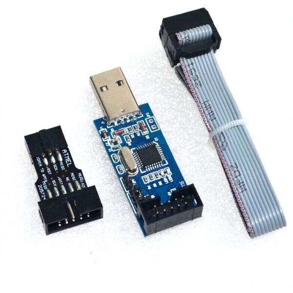
The USBISP USBASP AVR Programmer with a 10-pin to 6-pin Adapter is a versatile tool designed for programming AVR microcontrollers through a USB connection. This programmer is equipped with a 10-pin ISP (In-System Programming) connector and includes a 10-pin to 6-pin adapter to support various microcontroller configurations. It is ideal for electronics development, firmware updating, and prototyping with AVR-based microcontroller systems.
Key Features:
- USB interface for convenient connection to a computer
- Supports a broad range of AVR microcontrollers
- Includes a 10-pin to 6-pin adapter for versatile programming options
- Compatible with popular programming software like AVRDUDE
- Reliable and efficient programming with support for various programming modes
- Compact and portable design with an integrated USB cable
Technical Specifications:
- Interface: USB 2.0
- Supported Microcontrollers: ATtiny series, ATmega series, and other AVR microcontrollers
- Programming Voltage: 5V (can be powered via USB or external supply)
- Programming Modes: ISP (In-System Programming), HVSP (High-Voltage Serial Programming)
- Adapter: 10-pin to 6-pin adapter included
- Operating Temperature Range: 0°C to 70°C
- Dimensions (Programmer): Approximately 50mm x 30mm x 10mm (may vary slightly by manufacturer)
- Dimensions (Adapter): Approximately 25mm x 15mm x 5mm
- Weight: Approximately 30g (including adapter)
Applications:
- Firmware Uploading: Ideal for uploading firmware and software to AVR microcontrollers.
- Prototyping: Facilitates electronics development and prototyping with AVR-based systems.
- Development: Useful for developing and debugging AVR microcontroller applications.
- Educational: Suitable for educational use in learning about microcontroller programming and electronics.
Usage:
- Connect the USBISP USBASP programmer to your computer using the USB interface.
- Attach the 10-pin to 6-pin adapter to the programmer and then connect it to the target AVR microcontroller.
- Open compatible programming software (e.g., AVRDUDE) on your computer.
- Configure the software settings according to your specific microcontroller and programming needs.
- Upload the firmware or software to the microcontroller and monitor the programming status.
Caution:
- Ensure proper connections to prevent damage to the microcontroller or programmer.
- Use the correct voltage settings and programming parameters to avoid malfunction.
- Handle the programmer and adapter carefully to avoid physical damage.
|
The Allen key, also known as a hex key or hex wrench, is a small hand tool used to drive screws and bolts with hexagonal sockets. The Size 4 mm Allen key is designed to fit fasteners with a 4 mm hexagonal socket. This tool is commonly used in various mechanical, electrical, and DIY applications.
Key Features:
- Size: 4 mm (hexagonal socket size)
- Shape: L-shaped or T-shaped
- Material: Typically made from steel or chrome vanadium for durability and strength
- Finish: Often coated with black oxide or chrome plating for corrosion resistance
- Type: Can come in various designs such as short or long arm, ball-end, or standard
Technical Specifications:
- Hexagon Size: 4 mm
- Length: Varies depending on design (e.g., 60 mm to 150 mm for short arm, longer for T-handle or L-handle)
- Material: Steel, chrome vanadium, or other hardened materials
- Finish: Black oxide, chrome-plated, or other protective coatings
Applications:
- Mechanical Work: Used in automotive repair, machinery assembly, and other mechanical tasks.
- Furniture Assembly: Commonly used for assembling flat-pack furniture.
- Bicycles: Used for adjusting and tightening components on bicycles.
- Electronics: Helpful in assembling and repairing electronic devices with hex screws.
- DIY Projects: Essential for various home improvement and hobbyist tasks.
Datasheet:
Typically, Allen keys do not have detailed datasheets, but specifications can be obtained from this datasheet.
|
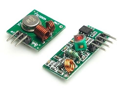
RF (Radio Frequency) Transmitters and Receivers are essential components for wireless communication systems. They are used to transmit and receive radio signals over a distance, making them ideal for remote control, data transmission, and wireless sensor networks. These modules are compact, efficient, and easy to integrate into various electronic projects, providing a reliable solution for wireless communication.
Key Features:
- Wireless Communication: Enables data transmission without physical connections.
- Compact Design: Small size suitable for integration in various projects.
- High Frequency: Operates 433 MHz for clear and stable communication.
- Low Power Consumption: Efficient operation for battery-powered applications.
- Easy Integration: Simple interfacing with microcontrollers and other digital devices.
- Long Range: Capable of transmitting signals over significant distances, depending on the environment and power output.
Technical Specifications:
- Frequency: 433 MHz
- Operating Voltage: 3V to 12V (varies by model)
- Data Rate: Up to 10 kbps (varies by model)
- Range: Up to 100 meters (open space, line of sight)
- Modulation: ASK (Amplitude Shift Keying) / OOK (On-Off Keying)
- Transmitter Power: Typically 10mW (varies by model)
- Receiver Sensitivity: Typically -105 dBm (varies by model)
Applications:
- Remote Controls: Used in remote control systems for various appliances and devices.
- Wireless Data Transmission: Transfer data between microcontrollers without physical connections.
- Home Automation: Control lights, doors, and other home systems wirelessly.
- Wireless Sensor Networks: Collect and transmit sensor data over a wireless network.
- Robotics: Implement wireless communication between robots and control systems.
- Security Systems: Use in alarm systems for transmitting signals from sensors to central units.
Usage:
- Wiring: Connect the transmitter and receiver modules to your microcontroller or control circuit.
- Programming: Write code to send and receive data wirelessly using available libraries for platforms like Arduino.
- Testing: Test the communication range and reliability in your specific environment.
- Integration: Integrate the modules into your final project, ensuring a stable power supply and secure connections.
Caution:
- Interference: Avoid placing near other electronic devices that may cause interference.
- Antenna: Use appropriate antennas to maximize range and signal strength.
- Power Supply: Ensure the modules are supplied with the correct voltage to avoid damage.
- Legal Compliance: Adhere to local regulations regarding RF transmissions and frequencies.
Datasheet:
For detailed technical specifications, refer to the RF Transmitter and Receiver Datasheet.
|
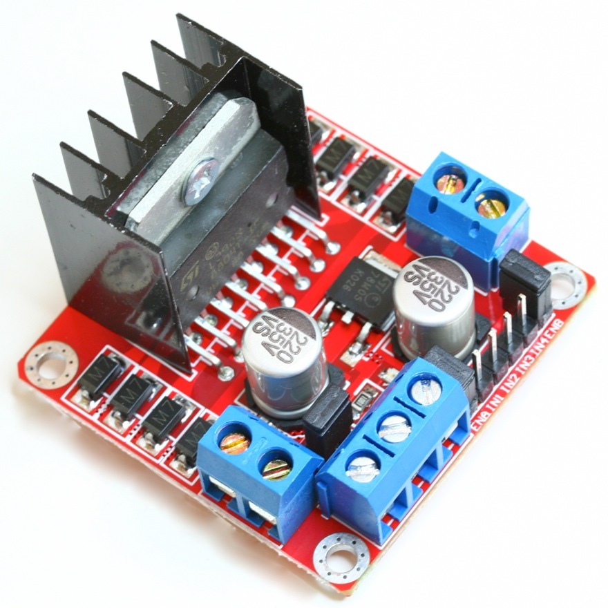
The L298N Dual H Bridge DC Stepper Motor Driver is a robust and versatile module used for controlling DC and stepper motors in various electronic projects. This driver module can control the speed and direction of two DC motors or a single stepper motor, making it ideal for robotics, automation, and other motor control applications. It features an onboard 5V regulator and can handle high currents, ensuring reliable operation in demanding environments.
Key Features:
- Motor Control: Dual H Bridge for controlling two DC motors or one stepper motor
- Voltage Range: Supports motor voltage from 5V to 35V
- Current Handling: Each bridge can handle up to 2A
- Onboard 5V Regulator: Provides 5V output for powering external circuits
- Control Pins: Enable and direction control for each motor
- Protection: Built-in thermal shutdown and overcurrent protection
- Compact Design: Easy to integrate into various projects
Technical Specifications:
- Motor Voltage: 5V to 35V
- Current Handling: 2A per bridge (peak 3A)
- Logic Voltage: 5V
- Control Inputs: 4 (IN1, IN2, IN3, IN4) for direction control
- Enable Pins: 2 (EN1, EN2) for enabling the motors
- Output Voltage: 5V (when using onboard regulator)
- Dimensions: 43mm x 43mm x 27mm
Applications:
- Robotics: Control of DC motors and stepper motors in robots.
- Automation: Use in automated systems for precise motor control.
- DIY Projects: Ideal for hobbyists and makers building motorized projects.
- Industrial Control: Suitable for controlling motors in industrial equipment.
- Educational Kits: Commonly used in learning modules for motor control.
Usage:
- Power Supply: Connect the motor power supply to the VCC and GND terminals, ensuring it is within the specified voltage range.
- Motor Connection: Connect the DC motors or stepper motor to the output terminals (OUT1, OUT2, OUT3, OUT4).
- Control Inputs: Use the control pins (IN1, IN2, IN3, IN4) to set the direction of the motors. The enable pins (EN1, EN2) can be used to enable or disable the motors.
- Logic Power: If using the onboard 5V regulator, connect the 5V and GND pins to your microcontroller or control circuit.
- Programming: Write code to control the motor speed and direction using PWM signals and logic inputs.
Caution:
- Heat Dissipation: The module can get hot during operation. Use a heat sink or cooling fan if necessary.
- Voltage and Current Limits: Do not exceed the specified voltage and current ratings to prevent damage.
Datasheet:
For detailed technical specifications, refer to the L298N Dual H Bridge DC Stepper Motor Driver Datasheet.
|
The AS608 Optical Fingerprint Module is a compact and efficient fingerprint recognition device designed for integration into security systems. It uses optical fingerprint sensing technology to capture and store fingerprint data, providing high accuracy and reliability in biometric authentication. The module is suitable for various applications, including access control, time attendance systems, and personal identification.
Key Features:
- High-precision optical fingerprint sensor
- Fast and accurate fingerprint recognition
- Supports fingerprint storage and matching
- Easy to integrate with microcontrollers and development boards
- Low power consumption
- Built-in algorithm for fingerprint processing
- UART interface for communication
Technical Specifications:
- Supply Voltage: 3.6V to 6V DC
- Operating Current: <120mA
- Fingerprint Capacity: 162 templates
- Verification Time: <1 second
- False Acceptance Rate (FAR): <0.001%
- False Rejection Rate (FRR): <0.1%
- Interface: UART (TTL logic level)
- Communication Speed: 9600 baud (default, adjustable)
- Working Temperature: -20°C to 50°C
- Dimensions: 32mm x 32mm x 10mm
- Weight: 20g
Applications:
- Access control systems
- Time attendance systems
- Personal identification devices
- Biometric authentication systems
- Safe and locker systems
- IoT security applications
Usage:
- Connect the module to a microcontroller or development board using the UART interface.
- Supply the appropriate voltage to power the module.
- Use the provided library or code examples to enroll and verify fingerprints.
- Integrate the fingerprint matching results into your security system.
Caution:
- Avoid exposing the sensor to direct sunlight or intense light.
- Keep the sensor clean for optimal performance.
- Handle the module with care to prevent damage to the optical sensor.
Datasheet:
For detailed technical specifications, refer to the AS608 Optical Fingerprint Module Datasheet.
|
The PICkit 2 is a popular in-circuit debugger and programmer developed by Microchip Technology for programming PIC microcontrollers. It is used for both development and production purposes, providing reliable and efficient programming capabilities. The ZIF (Zero Insertion Force) Adapter is an accessory that facilitates the easy insertion and removal of PIC microcontrollers during programming, making it ideal for development and testing phases.
Key Features:
- In-circuit debugger and programmer for PIC microcontrollers
- Supports a wide range of PIC microcontrollers
- Includes a ZIF Adapter for easy microcontroller handling
- Provides both programming and debugging capabilities
- User-friendly software interface with MPLAB IDE integration
- USB interface for connection to the development PC
- Reliable programming with error checking and verification
Technical Specifications:
- Device Supported: PIC microcontrollers
- Programming Interface: In-circuit (ICSP) and ZIF adapter
- ZIF Adapter Type: 40-pin or as specified (varies by model)
- Connection Interface: USB
- Operating Voltage: Typically 5V (from USB or external supply)
- Programming Speed: High-speed programming capability
- Software: MPLAB IDE or compatible programming software
- Operating Temperature Range: Typically 0°C to +70°C (varies by model)
Applications:
- Microcontroller development and testing
- Prototype programming and debugging
- Production programming for small to medium runs
- Educational projects and labs
- Embedded systems design
Usage:
- Connect the PICkit 2 to your PC via the USB interface and install the necessary software (MPLAB IDE or compatible).
- Attach the PIC microcontroller to the ZIF adapter, ensuring proper alignment and secure placement.
- Connect the ZIF adapter to the PICkit 2 programmer.
- Use the software to load the firmware or code into the microcontroller, configure debugging settings, and start programming.
- Verify the programming and debug the microcontroller as needed.
Caution:
- Ensure the correct microcontroller type and settings are selected in the software to avoid programming errors.
- Handle the ZIF adapter and microcontroller carefully to avoid physical damage or misalignment.
- Verify power supply and connections before starting the programming process to prevent damage to the programmer or microcontroller.
Datasheet:
For detailed technical specifications, refer to the PICkit 2 Datasheet and the ZIF Adapter Datasheet.
|
The EZP2019 is a high-speed SPI FLASH programmer designed for reading, writing, and erasing SPI flash memory chips. It supports a wide range of flash memory types and provides a reliable and efficient solution for programming tasks in electronics development and repair.
Key Features:
- High-Speed Programming: Fast read, write, and erase operations for SPI flash memory.
- Wide Compatibility: Supports a variety of SPI flash memory chips from different manufacturers.
- USB Interface: Connects to a computer via USB for easy operation and power supply.
- User-Friendly Software: Intuitive software interface for managing programming tasks.
- Compact Design: Portable and lightweight, making it easy to use in different environments.
- Versatile Use: Suitable for development, testing, and repair of electronic devices.
Technical Specifications:
- Supported Flash Memory: Wide range of SPI flash memory chips (e.g., 25 series, 24 series)
- Communication Interface: USB 2.0
- Power Supply: USB-powered
- Operating System Compatibility: Windows XP/7/8/10 (software support)
- Programming Voltage: Typically 1.8V to 5.0V (adjustable depending on chip requirements)
- Dimensions: Compact form factor for ease of use and portability
Applications:
- Firmware Development: Writing and updating firmware on SPI flash memory chips.
- Device Repair: Reprogramming flash memory in devices such as routers, modems, and other electronics.
- Prototyping: Used in the development and testing of new electronic products.
- Hobbyist Projects: Ideal for electronics enthusiasts working on custom projects involving SPI flash memory.
- Educational Use: Teaching tool for understanding flash memory programming and electronics development.
Datasheet:
For detailed technical information, refer to the EZP2019 High-Speed SPI FLASH Programmer datasheet.
|
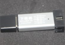
The ST-LINK V2 is a powerful in-circuit debugger and programmer for STM8 and STM32 microcontrollers. It provides an essential tool for developers working with STM8 and STM32 families of microcontrollers, offering support for debugging, programming, and development tasks.
Key Features:
- In-Circuit Debugger and Programmer: Supports both STM8 and STM32 microcontrollers for development and debugging.
- USB Interface: Connects to your computer via USB for easy setup and communication.
- High-Speed Communication: Provides fast programming and debugging with efficient data transfer.
- Compatible Software: Works with popular development environments such as STM32CubeIDE and KEIL uVision.
- Support for Multiple Devices: Compatible with a wide range of STM8 and STM32 microcontrollers.
Technical Specifications:
- Microcontroller Support: STM8 and STM32 families
- Interface: USB 2.0
- Debugging Features: Includes support for SWD (Serial Wire Debug) and JTAG debugging interfaces.
- Programming Features: Supports programming via SWD and JTAG.
- Power Supply: Powered via USB connection
- Operating System Compatibility: Windows, Linux (with additional drivers), macOS (with additional drivers)
- Dimensions: Compact design for easy integration into development setups
Applications:
- Microcontroller Development: Essential tool for developing and debugging applications using STM8 and STM32 microcontrollers.
- Embedded Systems: Used in embedded system design and development for programming and testing.
- Prototyping: Ideal for prototyping and validating designs with STM microcontrollers.
- Educational Purposes: Useful for educational and training purposes in microcontroller programming and debugging.
Datasheet:
For detailed technical specifications, refer to the ST-LINK V2 Datasheet.
|
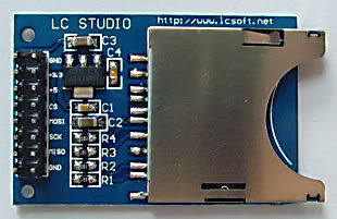
The SD Card Module is a compact and efficient solution for adding storage capabilities to your microcontroller or development board projects. It allows you to read from and write to SD cards, making it ideal for data logging, file storage, and other applications requiring large amounts of memory. The module supports various SD card formats and interfaces seamlessly with popular microcontrollers like Arduino, Raspberry Pi, and others.
Key Features:
- Storage: Supports SD, SDHC, and MicroSD (with adapter) cards
- Interface: SPI interface for easy integration
- Voltage Compatibility: Operates at 3.3V and 5V
- Onboard 3.3V Regulator: Ensures stable operation
- Card Detection: Built-in card detection switch
- Compact Design: Small footprint for easy incorporation into projects
- File System: Compatible with FAT16 and FAT32 file systems
Technical Specifications:
- Supported Cards: SD, SDHC, MicroSD (with adapter)
- Operating Voltage: 3.3V/5V
- Interface: SPI
- Current Consumption: < 100mA
- File System: FAT16, FAT32
- Dimensions: 42mm x 24mm x 12mm
Applications:
- Data Logging: Store sensor data and logs in embedded systems.
- File Storage: Save files for multimedia applications and projects.
- Firmware Updates: Load new firmware from the SD card for microcontrollers.
- DIY Projects: Perfect for hobbyists needing additional storage.
- Educational Projects: Commonly used in learning modules for data storage and retrieval.
Usage:
- Wiring: Connect the SD card module to your microcontroller using the SPI interface (CS, MOSI, MISO, SCK, VCC, GND).
- Power Supply: Ensure the module is powered with 3.3V or 5V, as required.
- Card Insertion: Insert a formatted SD card into the module.
- Programming: Use libraries (e.g., SD library for Arduino) to initialize the SD card and read/write data.
- Data Handling: Store or retrieve data files from the SD card as needed by your application.
Caution:
- Voltage Levels: Ensure proper voltage levels to avoid damaging the module.
- Handling SD Cards: Handle SD cards with care to prevent data loss or corruption.
Datasheet:
For detailed technical specifications, refer to the SD Card Module Datasheet.
|
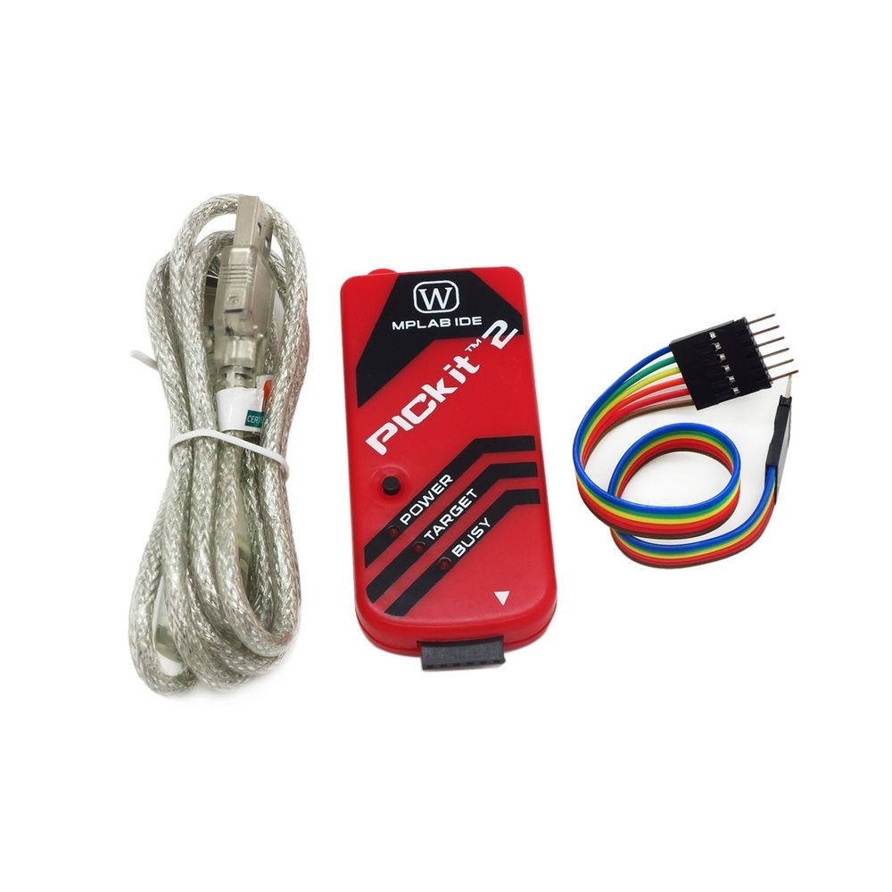
The PICkit 2 is a low-cost in-circuit debugger and programmer developed by Microchip Technology for programming and debugging PIC microcontrollers. It provides an easy and efficient way to develop, program, and test microcontroller-based projects. The PICkit 2 supports a wide range of PIC microcontrollers and offers a user-friendly interface for seamless integration with the MPLAB IDE.
Key Features:
- Supports a wide range of PIC microcontrollers
- In-circuit programming and debugging capabilities
- USB interface for connection to the development PC
- User-friendly interface with MPLAB IDE integration
- Low-cost and portable design
- Can be used as a programmer, debugger, and logic tool
- Built-in over-voltage/short-circuit protection
Technical Specifications:
- Supported Devices: Wide range of PIC microcontrollers
- Interface: USB 2.0
- Programming Voltage: 2.0V to 5.5V
- Operating Voltage: 5V (from USB)
- Current Consumption: Typically 20mA to 25mA
- Dimensions: Approximately 75mm x 25mm x 11mm (varies slightly by manufacturer)
- Operating Temperature Range: 0°C to +70°C
Applications:
- Microcontroller development and debugging
- Programming and testing of embedded systems
- Educational and learning projects
- Small-scale production programming
- Prototyping and hobbyist projects
Usage:
- Connect the PICkit 2 to your PC via the USB interface and install the necessary software (MPLAB IDE or compatible).
- Connect the PIC microcontroller to the PICkit 2 using the ICSP (In-Circuit Serial Programming) interface.
- Use the MPLAB IDE to load the firmware or code into the microcontroller, configure debugging settings, and start programming.
- Verify the programming and debug the microcontroller as needed using the PICkit 2.
Caution:
- Ensure the correct microcontroller type and settings are selected in the software to avoid programming errors.
- Handle the PICkit 2 and microcontroller carefully to avoid physical damage.
- Verify power supply and connections before starting the programming process to prevent damage to the programmer or microcontroller.
Datasheet:
For detailed technical specifications, refer to the PICkit 2 User Guide.
|
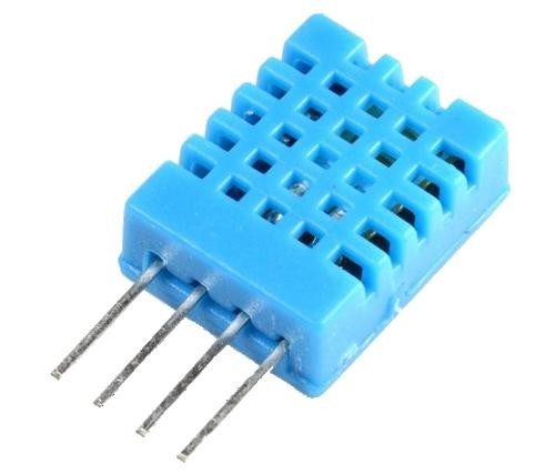
The DHT11 is a basic, ultra-low-cost digital temperature and humidity sensor. It uses a capacitive humidity sensor and a thermistor to measure the surrounding air and outputs a digital signal on the data pin. It’s simple to use but requires careful timing to grab data. It’s perfect for DIY projects, weather stations, and other applications where accurate and reliable temperature and humidity readings are needed.
Key Features:
- Temperature Range: 0-50°C with ±2°C accuracy
- Humidity Range: 20-80% RH with ±5% RH accuracy
- Low Power Consumption: Efficient for battery-operated applications
- Single Wire Digital Interface: Easy to interface with microcontrollers
- Pre-calibrated: No need for additional calibration
- Compact Size: Suitable for compact projects and devices
Technical Specifications:
- Temperature Range: 0-50°C (32-122°F)
- Humidity Range: 20-80% RH
- Temperature Accuracy: ±2°C
- Humidity Accuracy: ±5% RH
- Operating Voltage: 3.3V to 5.5V
- Max Current: 2.5mA
- Output: Digital signal via 1-wire protocol
- Dimensions: 15.5mm x 12mm x 5.5mm
Applications:
- Weather Stations: Monitor and log temperature and humidity levels.
- Home Automation: Control HVAC systems based on environmental conditions.
- Greenhouses: Maintain optimal growing conditions for plants.
- DIY Projects: Perfect for hobbyists building custom sensors and gadgets.
- Data Loggers: Record environmental data over time for analysis.
- Educational Projects: Teach students about sensors and data acquisition.
Usage:
- Wiring: Connect the VCC pin to 3.3V or 5V, GND to ground, and the DATA pin to a digital input on your microcontroller.
- Library Integration: Use libraries available for platforms like Arduino or Raspberry Pi to simplify reading data from the sensor.
- Coding: Write code to initialize the sensor and read temperature and humidity data.
- Data Processing: Process and use the sensor data in your application as needed, such as displaying it on an LCD or sending it to a web server.
Caution:
- Power Supply: Ensure the sensor is supplied with the correct voltage to avoid damage.
- Environmental Conditions: Keep the sensor in a dust-free, non-condensing environment for accurate readings.
- Wiring Length: Minimize the length of wiring between the sensor and the microcontroller to maintain signal integrity.
Datasheet:
For detailed technical specifications, refer to the DHT11 Datasheet.
|
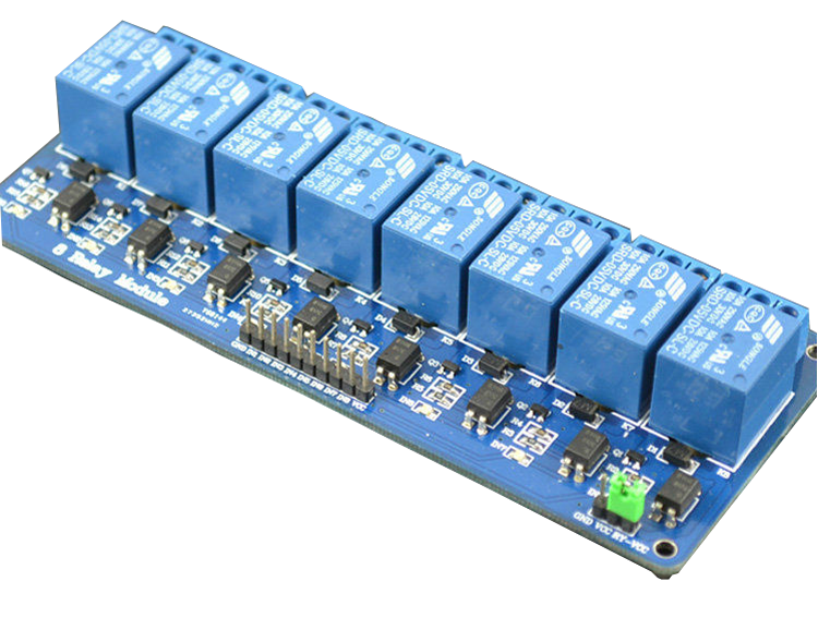
The 8 Channel Relay Module is a versatile and reliable module designed to control multiple high-power devices using a microcontroller or development board. Each relay can switch devices up to 10A at 250V AC or 30V DC, making it suitable for home automation, industrial control, and other applications requiring multiple relay operations. The module provides isolation and protection, ensuring safe and efficient control of electrical loads.
Key Features:
- Channels: 8 relays for controlling multiple devices
- Relay Capacity: Each relay can handle up to 10A at 250V AC or 30V DC
- Control Voltage: Compatible with 5V control signals
- Optocoupler Isolation: Provides isolation between the control signal and the relay, enhancing safety
- LED Indicators: Each relay has an LED indicator for visual status confirmation
- Common, Normally Open (NO), Normally Closed (NC) Contacts: Flexible wiring options for various applications
Technical Specifications:
- Number of Relays: 8
- Relay Type: SPDT (Single Pole Double Throw)
- Control Voltage: 5V DC
- Relay Voltage: 250V AC, 30V DC
- Relay Current: 10A
- Isolation: Optocoupler isolation
- Dimensions: 138mm x 56mm x 19mm
Applications:
- Home Automation: Control lights, fans, and other appliances remotely.
- Industrial Automation: Manage industrial equipment and machinery.
- DIY Projects: Ideal for hobbyists and makers requiring multiple relay controls.
- Security Systems: Control locks, alarms, and other security devices.
- Robotics: Operate various actuators and motors in robotics projects.
Usage:
- Wiring: Connect the relay module to your microcontroller or development board, ensuring correct connections for VCC, GND, and control pins.
- Power Supply: Provide a 5V power supply to the module.
- Control Signals: Use the control pins to activate or deactivate the relays.
- Connecting Loads: Connect the devices to be controlled to the relay terminals (COM, NO, NC) as per your requirement.
- Programming: Write code to control the relays based on your application’s logic.
Caution:
- High Voltage Handling: Be cautious when working with high voltages. Ensure proper insulation and safety measures.
- Proper Wiring: Verify all connections before powering the module to avoid short circuits or damage.
Datasheet:
For detailed technical specifications, refer to the 8 Channel Relay Module Datasheet.
|
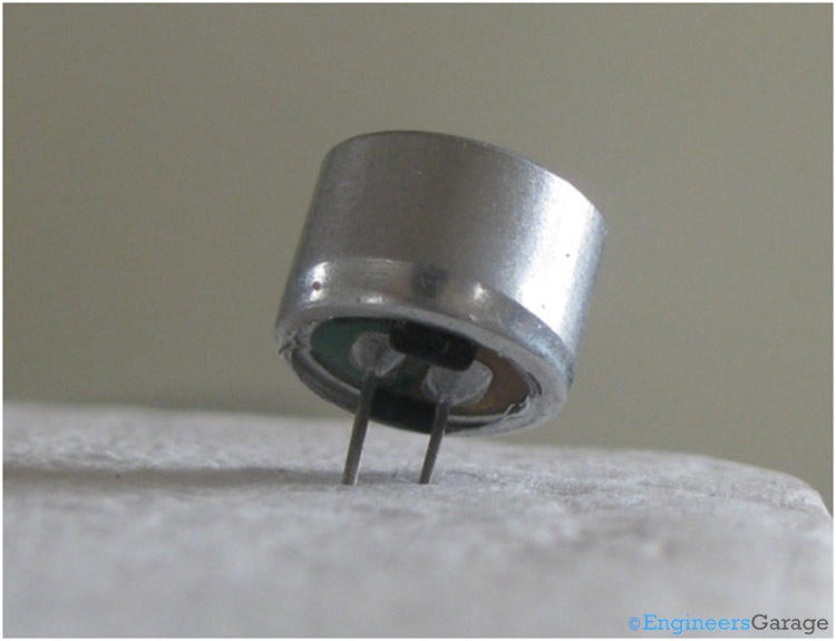
The Condenser Mic 4.5×2.2mm is a small-sized, high-sensitivity electret microphone. It is designed for a wide range of audio applications, including voice recording, telecommunication devices, and various consumer electronics. Its compact size and high sensitivity make it ideal for embedding in small devices.
Key Features:
- High sensitivity and low noise
- Small and compact size
- Wide frequency response
- Low power consumption
- Omnidirectional pickup pattern
- Easy to integrate into electronic circuits
Technical Specifications:
- Type: Electret condenser microphone
- Dimensions: 4.5mm (diameter) x 2.2mm (height)
- Sensitivity: -42dB ±3dB (0dB = 1V/Pa at 1kHz)
- Frequency Response: 20Hz to 16kHz
- Impedance: ≤ 2.2kΩ
- Operating Voltage: 1.5V to 10V DC
- Current Consumption: ≤ 0.5mA
- Signal-to-Noise Ratio: ≥ 60dB
- Directivity: Omnidirectional
- Operating Temperature Range: -20°C to +70°C
Applications:
- Voice recording devices
- Telecommunication equipment
- Hearing aids
- Portable audio recorders
- Consumer electronics
- Smart home devices
- Speech recognition systems
Usage:
- Connection:
- Connect the microphone’s output pin to the input of an amplifier or preamp circuit.
- Connect the power supply (1.5V to 10V DC) to the microphone.
- Ensure the ground connection is properly made to avoid noise interference.
- Integration:
- Place the microphone in a suitable location to capture sound effectively.
- Embed the microphone in devices ensuring the sound entry is not obstructed.
- Circuit Design:
- Use appropriate capacitors and resistors as per the microphone’s requirements.
- Design the circuit to provide a stable power supply and proper impedance matching.
Caution:
- Handle the microphone with care to avoid physical damage.
- Protect the microphone from exposure to moisture and extreme temperatures.
- Avoid applying excessive voltage to prevent damage to the microphone.
Datasheet:
For detailed technical specifications, refer to the Condenser Microphone Datasheet.
|
The PICkit 3 with ZIF Adapter is a programmer and debugger tool designed for use with Microchip’s PIC microcontrollers and dsPIC Digital Signal Controllers (DSCs). The PICkit 3 offers an easy and reliable way to program and debug PIC microcontrollers directly from the MPLAB IDE software. The included ZIF (Zero Insertion Force) adapter enhances the usability by providing a convenient and secure way to insert and remove microcontroller chips without damaging the pins, making it ideal for frequent programming and development tasks.
Key Features:
- Supports a wide range of PIC microcontrollers and dsPIC DSCs
- Direct connection to the MPLAB IDE software for programming and debugging
- USB connectivity for easy interface with a computer
- Real-time execution and debugging capabilities
- Integrated ZIF adapter for easy chip insertion and removal
- Compact and portable design
Technical Specifications:
- Programmer Type: In-Circuit Debugger (ICD) and Programmer
- Connectivity: USB 2.0 interface
- Supported Devices: Wide range of PIC microcontrollers and dsPIC DSCs
- Programming Voltage: 2.0V to 5.5V
- Debugging Features: Real-time execution, breakpoints, single-step, and variable inspection
- ZIF Adapter: 28-pin socket for easy insertion and removal of chips
- Dimensions: Typically 95mm x 62mm x 25mm (programmer), 80mm x 30mm x 20mm (ZIF adapter)
Applications:
- Development and prototyping with PIC microcontrollers
- Educational purposes and learning about microcontroller programming
- Firmware debugging and testing
- Programming PIC microcontrollers for embedded systems and projects
Usage:
- Connect the PICkit 3 to your computer via the USB cable.
- Install the necessary drivers and MPLAB IDE software from Microchip’s website.
- Insert the PIC microcontroller into the ZIF adapter, ensuring correct orientation.
- Connect the ZIF adapter to the PICkit 3 programmer.
- Open the MPLAB IDE software and configure the programmer settings.
- Program and debug your PIC microcontroller using the MPLAB IDE interface.
Caution:
- Ensure correct orientation of the microcontroller in the ZIF adapter to avoid damaging the pins.
- Follow the recommended voltage levels and programming guidelines provided by Microchip.
- Handle the PICkit 3 and ZIF adapter carefully to prevent static discharge and physical damage.
Datasheet:
For detailed technical specifications, refer to the PICkit 3 with ZIF Adapter Datasheet.
|
The PIR (Passive Infrared) Motion Sensor is a reliable and efficient sensor used to detect motion by measuring changes in infrared radiation levels emitted by surrounding objects. It is widely used in security systems, automatic lighting controls, and other applications requiring motion detection. The sensor is designed to detect human movement and can trigger alarms, lights, or other systems in response to detected motion.
Key Features:
- Type: Passive Infrared (PIR) motion sensor
- Detection Range: Up to 7 meters
- Detection Angle: 120 degrees
- Output: Digital high/low signal
- Operating Voltage: 5V to 20V
- Adjustable Sensitivity: Allows customization of detection range
- Adjustable Time Delay: Configurable delay before resetting
- Compact Design: Small and easy to integrate into various systems
Technical Specifications:
- Operating Voltage: 5V to 20V
- Current Consumption: < 60µA
- Output Type: Digital (high/low)
- Detection Range: Up to 7 meters
- Detection Angle: 120 degrees
- Trigger Time: Adjustable from 5 seconds to 5 minutes
- Operating Temperature Range: -20°C to +50°C
- Dimensions: 32mm x 24mm
Applications:
- Security Systems: Use in burglar alarms and surveillance systems.
- Automatic Lighting: Control lights in homes, offices, and public spaces.
- Energy Saving: Automate lighting and devices to save energy.
- Consumer Electronics: Motion-activated gadgets and appliances.
- Industrial Automation: Detect movement in industrial processes and machinery.
Usage:
- Installation: Mount the PIR sensor at the desired location, ensuring a clear line of sight for detection.
- Power Supply: Connect the sensor to a power source within the operating voltage range.
- Output Connection: Connect the output pin to the desired control circuit or microcontroller.
- Adjustment: Use the sensitivity and time delay adjustments to fine-tune the sensor’s performance.
Caution:
- Environmental Factors: Avoid placing the sensor near heat sources or in direct sunlight to prevent false triggering.
- Proper Wiring: Ensure correct wiring to avoid damage to the sensor and connected devices.
Datasheet:
For detailed technical specifications, refer to the PIR Motion Sensor Datasheet.
|
