|
Description |
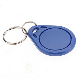
The 125KHZ RFID Key Chain is a compact and durable radio-frequency identification (RFID) device used for access control and identification applications. It operates at a frequency of 125kHz and is compatible with standard RFID readers. The key chain format makes it convenient to carry and use for various applications such as security systems, attendance tracking, and asset management.
Key Features:
- Operates at 125kHz frequency
- Durable and compact key chain design
- Compatible with standard RFID readers
- Unique identification number (UID) for each key chain
- Waterproof and shock-resistant
- Long read range (up to 10 cm depending on the reader)
- No battery required (passive RFID technology)
Technical Specifications:
- Operating Frequency: 125kHz
- Material: ABS plastic
- Dimensions: Approximately 40mm x 32mm x 4mm
- Weight: Approximately 6g
- Read Range: Up to 10 cm (depending on the reader and environment)
- Data Storage: 64-bit read-only unique identifier (UID)
- Operating Temperature Range: -25°C to +85°C
- Color: Typically blue, but may vary by manufacturer
- Waterproof: Yes
Applications:
- Access control systems
- Time and attendance tracking
- Membership management
- Asset tracking
- Secure entry systems
- Contactless payment systems
Usage:
- Integration:
- Enroll the RFID key chain in the desired RFID system by registering its unique identifier (UID) with the system’s database.
- Operation:
- Present the key chain to an RFID reader within the read range (up to 10 cm).
- The reader will capture the UID and communicate it to the control system for processing.
- Security:
- Use the key chain for secure access to restricted areas or for tracking attendance.
- Pair the key chain with a compatible RFID reader and control system for seamless operation.
Caution:
- Avoid exposing the key chain to extreme temperatures or harsh chemicals.
- Do not bend or apply excessive force to the key chain to prevent damage.
- Keep the key chain away from strong magnetic fields to ensure proper operation.
Datasheet:
For detailed technical specifications, refer to the manufacturer’s datasheet for your specific 125kHz RFID key chain model.
|
|
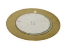
The Piezoelectric Transducer 27mm is a compact and efficient device used for converting electrical signals into mechanical vibrations or sound waves. It is commonly used in buzzers, alarms, and ultrasonic applications due to its ability to generate precise and high-frequency sounds. The transducer is highly reliable, lightweight, and suitable for various electronic projects and devices.
Key Features:
- High Sensitivity: Efficiently converts electrical energy into mechanical vibrations.
- Compact Size: 27mm diameter, suitable for space-constrained applications.
- Wide Frequency Range: Capable of generating a broad range of frequencies.
- Low Power Consumption: Operates efficiently with minimal power.
- Durable Construction: Designed for long-lasting performance.
- Easy Integration: Simple to integrate into various circuits and devices.
Technical Specifications:
- Diameter: 27mm
- Resonant Frequency: Typically around 4 kHz (varies by model)
- Capacitance: Typically 2000 pF at 1 kHz (varies by model)
- Operating Voltage: 3V to 30V (varies by model)
- Sound Pressure Level: Typically 85 dB at 10 cm and 5V (varies by model)
- Operating Temperature Range: -20°C to +60°C
- Material: Metal and ceramic
Applications:
- Buzzers and Alarms: Used in buzzers, alarms, and warning systems.
- Ultrasonic Cleaners: Integrated into ultrasonic cleaning devices.
- Medical Devices: Utilized in medical equipment for ultrasonic applications.
- Sonar Systems: Employed in sonar systems for underwater detection.
- Musical Instruments: Used in electronic musical instruments for sound generation.
- DIY Projects: Suitable for hobbyist and educational electronic projects.
Usage:
- Wiring: Connect the transducer to the appropriate points in your circuit, typically using driver circuits to control the input signal.
- Power Supply: Ensure the transducer is supplied with the correct voltage to prevent damage.
- Mounting: Secure the transducer in place within your device, ensuring it has sufficient space to vibrate freely.
- Testing: Test the transducer by applying the input signal and verifying the sound output or vibration.
Caution:
- Handling: Handle with care to avoid damage to the ceramic element.
- Voltage: Ensure correct voltage levels to avoid overloading the transducer.
- Environmental Conditions: Use within the specified temperature range to maintain performance.
Datasheet:
For detailed technical specifications, refer to the Piezoelectric Transducer 27mm Datasheet.
|
The RC522 RFID Module Kit is a complete solution for adding RFID functionality to your projects. The module operates at 13.56MHz and uses the MFRC522 IC for communication with RFID cards and tags. It is designed for easy integration with microcontroller platforms like Arduino, making it ideal for access control, attendance systems, and other identification applications.
Key Features:
- Operates at 13.56MHz frequency
- Compatible with ISO/IEC 14443 Type A cards
- Supports MIFARE1 S50, MIFARE1 S70, MIFARE Ultralight, MIFARE Pro, and MIFARE DESFire cards
- SPI, I2C, and UART communication interfaces
- Low power consumption
- High data transfer rate (up to 10 Mbit/s)
- Compact design and easy to use
- Comes with RFID cards and key fobs
Technical Specifications:
- Operating Frequency: 13.56MHz
- IC Chip: MFRC522
- Communication Interfaces: SPI, I2C, UART
- Power Supply Voltage: 3.3V
- Current Consumption: 13-26mA
- Read Range: Up to 5 cm (depending on the antenna size and tag type)
- Dimensions: 40mm x 60mm x 5mm
Kit Components:
- RC522 RFID Module
- 1 x MIFARE 1K S50 RFID Card
- 1 x RFID Key Fob
- Header pins for connection
- Jumper wires for easy interfacing
Applications:
- Access control systems
- Time and attendance tracking
- Contactless payment systems
- Inventory management
- Asset tracking
- DIY electronics projects
Usage:
- Wiring:
- Connect the RC522 RFID module to your microcontroller platform using SPI, I2C, or UART interfaces. For Arduino, the typical SPI connections are:
- VCC to 3.3V
- GND to GND
- RST to Pin 9
- IRQ (not used)
- MISO to Pin 12
- MOSI to Pin 11
- SCK to Pin 13
- SDA (SS) to Pin 10
- Programming:
- Install the necessary libraries (e.g., MFRC522 library for Arduino).
- Use example code to initialize the module and read RFID tags or cards.
- Testing:
-
- Present an RFID card or key fob to the module and observe the UID output on the serial monitor.
Caution:
- Ensure proper handling to avoid damage from electrostatic discharge (ESD).
- Verify power supply requirements to prevent damage to the module.
- Keep the module away from strong electromagnetic fields to ensure reliable operation.
Datasheet:
For detailed technical specifications, refer to the MFRC522 Datasheet.
|
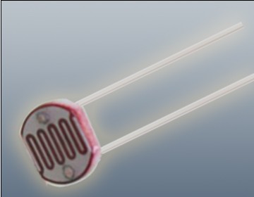
The Photoresistor LDR (Light Dependent Resistor) is a variable resistor whose resistance changes with the light intensity that falls upon it. It is widely used in light sensing applications and projects where detecting light levels is essential. LDRs are cost-effective, easy to use, and suitable for various electronic projects, including light meters, street lights, and other light-sensitive devices.
Key Features:
- Light Sensitivity: Resistance decreases with increasing light intensity
- Simple Interface: Easy to integrate with microcontrollers and analog circuits
- Low Cost: Economical solution for light detection
- Wide Range of Light Detection: Can detect various light levels from low to high intensity
- Compact Size: Fits easily into small projects
Technical Specifications:
- Resistance in Darkness: Typically 1MΩ (depending on specific model)
- Resistance in Bright Light: Typically 10-20kΩ (depending on specific model)
- Spectral Peak: Approximately 540nm (most sensitive to green light)
- Response Time: Rise time ~20ms, fall time ~30ms
- Operating Temperature Range: -30°C to +70°C
- Diameter: Typically 5mm to 10mm (depending on specific model)
Applications:
- Light Meters: Measure light intensity for photography and scientific applications.
- Street Lights: Automatic on/off control based on ambient light levels.
- Alarm Systems: Detect changes in light levels for security purposes.
- Consumer Electronics: Light-sensitive control in devices like clocks and displays.
- Educational Projects: Common component in learning modules for electronics.
Usage:
- Circuit Integration: Connect the LDR in a voltage divider circuit with a fixed resistor to create a variable voltage output based on light intensity.
- Microcontroller Interface: Read the voltage output from the LDR circuit using an analog input pin on a microcontroller.
- Programming: Write code to interpret the analog signal and perform actions based on light levels (e.g., turning on an LED when it gets dark).
- Testing: Calibrate the LDR circuit for the desired light sensitivity by adjusting the fixed resistor value.
Caution:
- Environment: Avoid exposure to extreme temperatures and humidity, which may affect the LDR’s performance.
- Handling: Handle with care to avoid damaging the sensitive surface of the LDR.
Datasheet:
For detailed technical specifications, refer to the Photoresistor LDR Datasheet.
|
The 125KHZ RFID Card is a contactless proximity card used for various identification and access control applications. It operates at a frequency of 125kHz and contains a unique identification number (UID) for each card. This card is durable and convenient, making it ideal for use in security systems, time and attendance tracking, and membership management.
Key Features:
- Operates at 125kHz frequency
- Durable PVC material
- Compatible with standard 125kHz RFID readers
- Unique identification number (UID) for each card
- Waterproof and tamper-resistant
- Long read range (up to 10 cm depending on the reader)
- No battery required (passive RFID technology)
Technical Specifications:
- Operating Frequency: 125kHz
- Material: PVC plastic
- Dimensions: 85.6mm x 54mm x 0.8mm (standard credit card size)
- Weight: Approximately 6g
- Read Range: Up to 10 cm (depending on the reader and environment)
- Data Storage: 64-bit read-only unique identifier (UID)
- Operating Temperature Range: -25°C to +85°C
- Color: Typically white, but may vary by manufacturer
- Waterproof: Yes
Applications:
- Access control systems
- Time and attendance tracking
- Membership management
- Asset tracking
- Secure entry systems
- Contactless payment systems
Usage:
- Integration:
- Enroll the RFID card in the desired RFID system by registering its unique identifier (UID) with the system’s database.
- Operation:
- Present the card to an RFID reader within the read range (up to 10 cm).
- The reader will capture the UID and communicate it to the control system for processing.
- Security:
- Use the card for secure access to restricted areas or for tracking attendance.
- Pair the card with a compatible RFID reader and control system for seamless operation.
Caution:
- Avoid exposing the card to extreme temperatures or harsh chemicals.
- Do not bend or apply excessive force to the card to prevent damage.
- Keep the card away from strong magnetic fields to ensure proper operation.
Datasheet:
For detailed technical specifications, refer to the manufacturer’s datasheet for your specific 125kHz RFID card model.
|
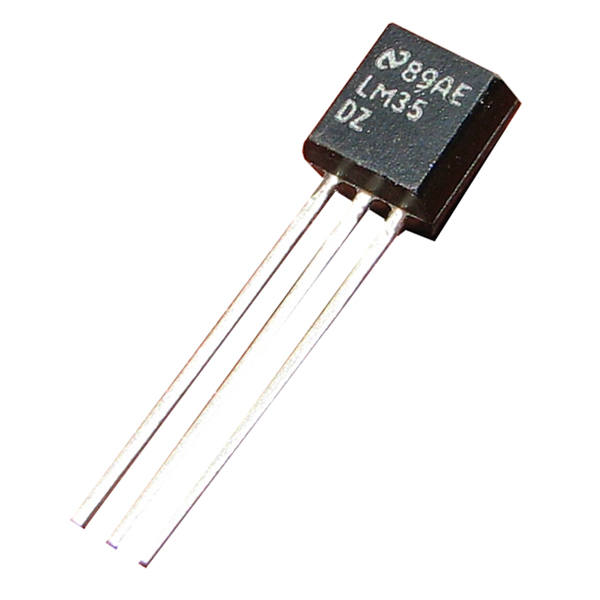
The LM35 is a precision temperature sensor with an analog output proportional to the temperature in degrees Celsius. This sensor offers high accuracy and linearity, making it ideal for a wide range of temperature measurement applications in both commercial and industrial environments. The LM35 does not require any external calibration or trimming, simplifying its use in embedded systems and temperature monitoring solutions.
Key Features:
- Type: Analog temperature sensor
- Accuracy: ±0.5°C at room temperature
- Range: -55°C to +150°C
- Linear Output: 10mV/°C
- Low Self-Heating: Less than 0.1°C in still air
- Wide Operating Voltage: 4V to 30V
- Low Impedance Output: Can drive up to 1mA load
- Calibration: Factory calibrated in Celsius
Technical Specifications:
- Output Voltage: 10mV per °C
- Operating Voltage: 4V to 30V
- Temperature Range: -55°C to +150°C
- Accuracy: ±0.5°C at 25°C
- Self-Heating: 0.08°C in still air
- Response Time: 1.5 seconds (typical)
- Output Impedance: Low impedance output (less than 1 ohm)
- Package Type: TO-92, SO-8, TO-220
Applications:
- Temperature Measurement: Suitable for HVAC systems, environmental monitoring, and home appliances.
- Thermal Protection: Can be used for thermal shutdown and temperature control in electronic devices.
- Industrial Equipment: Monitoring temperature in industrial machinery and processes.
- Consumer Electronics: Used in gadgets, computers, and other electronic products for temperature sensing.
- Automotive: Temperature monitoring in automotive systems and engines.
Usage:
- Circuit Integration: Connect the LM35 sensor to a microcontroller or analog-to-digital converter (ADC) to read temperature data.
- Power Supply: Provide a stable voltage within the operating range (4V to 30V).
- Temperature Reading: Measure the output voltage, which corresponds to the temperature (e.g., 250mV equals 25°C).
Caution:
- Proper Wiring: Ensure correct wiring to avoid damage to the sensor.
- Environment: Protect the sensor from extreme conditions beyond its specified range.
Datasheet:
For detailed technical specifications, refer to the LM35 Temperature Sensor Datasheet.
|
The Allen key, also known as a hex key or hex wrench, is a tool used to drive screws and bolts with hexagonal sockets. The Size 2.5 mm Allen key is designed specifically for fasteners with a 2.5 mm hexagonal socket. This small-sized Allen key is commonly used in precision applications where smaller fasteners are involved.
Key Features:
- Size: 2.5 mm (hexagonal socket size)
- Shape: Typically L-shaped or T-shaped
- Material: Generally made from high-strength steel or chrome vanadium for durability
- Finish: Often coated with black oxide, chrome plating, or other protective finishes
- Type: Available in various designs, such as short or long arm, and sometimes with a ball end for angled access
Technical Specifications:
- Hexagon Size: 2.5 mm
- Length: Varies by design, e.g., 50 mm to 100 mm for short arms, longer for T-handle or L-handle versions
- Material: Steel, chrome vanadium, or other hardened materials
- Finish: Black oxide, chrome-plated, or other corrosion-resistant coatings
Applications:
- Precision Work: Ideal for small, delicate tasks such as electronics assembly or small machinery.
- Model Building: Commonly used in hobbies and model building where small screws are used.
- Bicycles: Useful for adjustments on bicycle components that require a smaller hex size.
- Furniture Assembly: Often used in assembling small parts of flat-pack furniture.
- Electronics: Essential for assembling and servicing electronic devices with tiny hex screws.
Datasheet:
Allen keys typically do not have detailed datasheets, but specifications can be found from tool manufacturers or suppliers.
|
The PLC44 to DIP40 IC Socket Adapter is designed to convert a 44-pin PLCC (Plastic Leaded Chip Carrier) IC package into a 40-pin DIP (Dual Inline Package) socket configuration. This adapter enables the use of PLCC ICs in DIP socket-compatible PCBs and prototyping setups, simplifying integration and testing.
Key Features:
- Convenient Conversion: Adapts a 44-pin PLCC IC for use with a 40-pin DIP socket.
- High-Quality Construction: Built with durable materials to ensure reliable connections and longevity.
- Gold-Plated Contacts: Provides excellent conductivity and corrosion resistance.
- Compact Form Factor: Suitable for use with standard breadboards and PCB mountings.
- Easy Installation: Allows for quick and straightforward installation and removal of ICs.
Technical Specifications:
- Package Type: PLC44 to DIP40
- Pin Pitch (PLCC): 1.27mm
- Pin Pitch (DIP): 2.54mm
- Material: FR4 PCB, Gold-plated contacts
- Dimensions: Varies by model
- Weight: Lightweight design
- Temperature Range: -40°C to +85°C
- Mounting Type: Through-hole
Applications:
- Prototyping: Enables the use of PLCC ICs on DIP-compatible breadboards and prototype boards.
- Development: Facilitates the integration of PLCC devices into DIP-based circuit designs.
- Repair and Replacement: Useful for adapting PLCC ICs in existing DIP-based systems or repairs.
- Educational Use: Ideal for demonstrating the use and conversion of different IC package types.
|
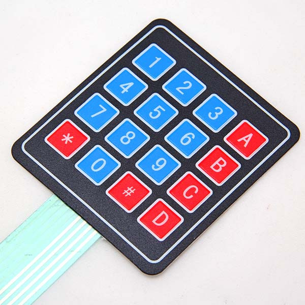
The 4×4 Matrix Keypad is a user-friendly input device consisting of 16 keys arranged in a 4×4 matrix. It is widely used in embedded systems, microcontroller projects, and DIY electronics for user input. Each key press is detected by scanning the matrix, allowing for efficient and reliable data entry. The keypad is compact, durable, and easy to integrate into various projects.
Key Features:
- Key Configuration: 4 rows and 4 columns, totaling 16 keys
- Interface: Matrix scanning
- Key Labels: Numeric and function keys (0-9, A-D, *, #)
- Compact Design: Suitable for handheld devices and small projects
- Durable: Made from high-quality materials for long-lasting use
- Flexible: Can be connected to any microcontroller or development board
- Low Power Consumption: Efficient operation with minimal power usage
Technical Specifications:
- Number of Keys: 16 (4×4 matrix)
- Operating Voltage: 3.3V to 5V
- Current Consumption: < 10mA
- Contact Resistance: ≤ 200 ohms
- Insulation Resistance: ≥ 100M ohms (at 250V DC)
- Operating Temperature Range: -20°C to +60°C
- Keypad Dimensions: 69mm x 69mm x 1.8mm
- Connection Type: 8-pin header
Applications:
- Embedded Systems: User input for microcontroller-based projects.
- DIY Electronics: Ideal for hobbyists and makers creating custom projects.
- Access Control: Use in security systems for code entry.
- Consumer Electronics: Keypad input for appliances and gadgets.
- Educational Projects: Commonly used in educational kits and learning modules.
Usage:
- Wiring: Connect the 8-pin header to the microcontroller or development board, ensuring correct row and column connections.
- Programming: Use libraries (e.g., Keypad library for Arduino) to read key presses and handle input.
- Integration: Incorporate the keypad into your project for reliable user input.
- Testing: Verify the functionality by pressing keys and checking the output.
Caution:
- Proper Connection: Ensure the keypad is connected correctly to avoid malfunction.
- Voltage Levels: Operate within the specified voltage range to prevent damage.
Datasheet:
For detailed technical specifications, refer to the 4×4 Matrix Keypad Datasheet.
|
The Tilt Sensor (Blue) is a versatile sensor designed to detect the angle of inclination or tilt in various applications. It uses a mercury switch or a ball-and-cup mechanism to detect changes in orientation. This sensor is commonly used in electronics projects, robotics, and systems where tilt detection is crucial for proper functioning or safety.
Key Features:
- Detection Mechanism: Mercury switch or ball-and-cup mechanism
- Output Type: Digital (Normally open or closed switch)
- Operating Voltage: 3V to 12V DC
- Sensitivity: Detects tilt at various angles (typically ±45°)
- Response Time: Instantaneous response to tilt changes
- Indicator: Blue color for easy identification
- Durability: Reliable and robust for various applications
Technical Specifications:
- Dimensions:
- Sensor Diameter: 25 mm
- Height: 10 mm
- Weight: Approximately 10 g
- Operating Voltage: 3V to 12V DC
- Output Type: Digital (On/Off switch)
- Tilt Angle: ±45° (varies by model)
- Response Time: Immediate (depends on tilt angle)
- Material: Plastic housing with internal tilt mechanism
- Cable Length: 15 cm (typically, varies by supplier)
Applications:
- Robotics: Detects the tilt of a robot to trigger actions or adjust orientation.
- Safety Systems: Used in devices to detect accidental tilting or tipping.
- Consumer Electronics: Helps in features that adjust based on the device’s tilt.
- Automotive: Used in vehicles for tilt detection and stability control.
- Games and Toys: Provides tilt-sensitive controls in gaming or interactive toys.
Datasheet:
For detailed technical information, refer to the Tilt Sensor (Blue) Datasheet.
|
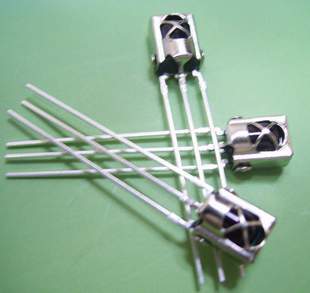
The TSOP 1838 is a compact IR (Infrared) receiver module designed for use in remote control systems. It can detect modulated IR signals at 38 kHz, making it ideal for applications such as remote control reception, IR data transmission, and IR-based communication systems. The TSOP 1838 provides high sensitivity and reliable performance in a small package.
Key Features:
- Pin diode and preamplifier in one package
- Modulated IR signal detection at 38 kHz
- High sensitivity and excellent noise immunity
- Low power consumption
- TTL and CMOS compatible output
- Internal filter for PCM frequency
- Improved shielding against electrical field disturbance
- Suitable for continuous and burst data transmission
Technical Specifications:
- Carrier Frequency: 38 kHz
- Supply Voltage: 2.7V to 5.5V
- Supply Current: 0.4 mA (typical)
- Peak Wavelength: 940 nm
- Reception Range: Up to 45 meters (with proper IR transmitter)
- Viewing Angle: ±45 degrees
- High-Level Output Voltage: ≥ Vcc – 0.2V
- Low-Level Output Voltage: ≤ 0.2V
- Output Pulse Width: Typically 400 µs
- Operating Temperature Range: -25°C to +85°C
- Package Type: 3-pin epoxy package
Applications:
- IR remote control systems
- Consumer electronics (TVs, VCRs, DVDs, audio equipment)
- Home automation
- IR data communication
- Infrared object detection
- Robotics
Usage:
- Connection:
- Connect the Vcc pin to a power supply (2.7V to 5.5V).
- Connect the GND pin to ground.
- Connect the OUT pin to the input of a microcontroller or other logic-level input device.
- Operation:
- When an IR signal at 38 kHz is received, the OUT pin goes low.
- When no IR signal is received, the OUT pin stays high.
- Use the output signal to control devices or process the data using a microcontroller.
- Interfacing:
- Interface the TSOP 1838 with a microcontroller to decode the received IR signals.
- Implement software to process the decoded IR signals for controlling various devices.
Caution:
- Ensure the IR receiver is not exposed to direct sunlight or strong ambient light sources, as this may affect its performance.
- Handle the module with care to avoid damage from electrostatic discharge (ESD).
Datasheet:
For detailed technical specifications, refer to the TSOP 1838 Datasheet.
|
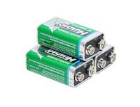
The 9V battery is a compact, rectangular-shaped battery commonly used in various electronic devices and household applications. Known for its reliability and long shelf life, the 9V battery provides a steady voltage output, making it ideal for devices that require a stable power source. It is widely used in smoke detectors, multimeters, transistor radios, and other portable electronic devices.
Key Features:
- Type: 9V battery
- Voltage: 9 volts
- Capacity: Varies by manufacturer (typically between 500mAh to 1200mAh)
- Shelf Life: Up to 5 years
- Size: Standard 9V (rectangular with snap connectors)
- Reliable Performance: Consistent and stable power output
- Leak-resistant: Designed to prevent leakage and protect devices
Technical Specifications:
- Voltage: 9V
- Capacity: Typically between 500mAh to 1200mAh
- Dimensions: 48.5mm x 26.5mm x 17.5mm
- Weight: Approximately 45g
- Terminal Type: Snap connector
- Chemistry: Available in Alkaline, Lithium, or Rechargeable NiMH
- Operating Temperature Range: -20°C to +54°C
Applications:
- Smoke Detectors: Reliable power source for safety devices.
- Multimeters: Provides consistent voltage for accurate measurements.
- Transistor Radios: Powers portable radios for extended periods.
- Portable Electronic Devices: Suitable for various battery-operated devices.
- Toys: Used in electronic toys and gadgets.
Usage:
- Installation: Insert the 9V battery into the device, ensuring correct polarity alignment.
- Replacement: Replace the battery when the device indicates low power or performance drops.
- Storage: Store batteries in a cool, dry place to maximize shelf life.
Caution:
- Proper Disposal: Follow local regulations for battery disposal.
- Avoid Short-circuiting: Do not connect terminals directly, as it may cause overheating or leakage.
- Do Not Recharge: Non-rechargeable 9V batteries should not be recharged.
Datasheet:
For detailed technical specifications, refer to the 9V Battery Datasheet.
|
A tilt sensor is a device used to detect the orientation or inclination of an object. It is typically used in various applications where it is necessary to detect changes in position or to determine if an object has tilted beyond a certain angle. Tilt sensors are widely used in robotics, automotive systems, security systems, and electronic devices for motion detection and orientation sensing.
Key Features:
- Detects changes in orientation or tilt
- Simple and reliable design
- Provides digital output signal
- Low power consumption
- Compact and easy to integrate
- Suitable for a wide range of applications
Technical Specifications:
- Type: Tilt Sensor
- Operating Voltage: Typically 3.3V to 5V (varies by model)
- Output Type: Digital (HIGH/LOW)
- Tilt Angle Range: Typically 15° to 45° (varies by model)
- Current Consumption: Typically less than 1mA
- Dimensions: Varies by product (commonly around 10mm x 5mm x 5mm)
- Operating Temperature Range: -40°C to +85°C
Applications:
- Robotics and automation
- Automotive safety systems
- Security and alarm systems
- Consumer electronics
- Motion detection and orientation sensing
- Industrial equipment
Usage:
- Connect the tilt sensor to your microcontroller or development board, ensuring proper connection of the power supply (VCC, GND) and the output pin.
- Use the digital output signal to detect tilt: the sensor typically outputs a HIGH signal when in the default position and a LOW signal when tilted beyond the specified angle.
- Implement code to monitor the sensor output and trigger appropriate actions or alarms when a tilt is detected.
- Mount the sensor on the object or surface where tilt detection is required, ensuring it is securely positioned.
Caution:
- Ensure proper orientation and mounting of the sensor for accurate tilt detection.
- Avoid exposing the sensor to excessive vibrations or shocks, which may affect its performance.
- Handle the sensor carefully to avoid damage to the internal components.
Datasheet:
For detailed technical specifications, refer to the specific product datasheet provided by the manufacturer.
|
A line tracking sensor is an infrared-based module used for detecting and following lines or paths on surfaces. It is commonly employed in robotics and automated systems to navigate predefined routes or tracks.
Key Features:
- Sensor Type: Infrared (IR) sensor module.
- Detection Method: Typically uses infrared light emitted by LEDs and reflected off the surface.
- Detection Capability: Can detect lines of contrasting colors (typically black on white or vice versa).
- Output: Digital signals indicating line detection (e.g., high or low) or analog signals proportional to the position on the line.
- Operating Voltage: Usually operates at 5V DC.
- Adjustability: Often adjustable sensitivity to fine-tune detection based on line width and surface reflectivity.
- Integration: Compact and designed for easy integration into robotic systems or line-following vehicles.
- Mounting: Typically includes mounting holes or brackets for easy installation.
Technical Specifications:
- Dimensions: Compact size suitable for various robotic applications.
- Operating Range: Suitable for indoor and controlled outdoor environments.
- Response Time: Fast response to changes in line position.
- Operating Temperature: Typically -10°C to +50°C.
Applications:
- Automated guided vehicles (AGVs)
- Line-following robots
- Industrial automation
- Educational robotics projects
Datasheet: For detailed technical information, refer to the Line Tracking Sensor datasheet.
|
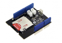
The SD Card Shield is a versatile and essential accessory for adding SD card storage to your Arduino projects. It allows you to read and write data to standard SD cards, enabling data logging, file storage, and other applications that require external storage. The shield is easy to integrate and compatible with various Arduino boards, making it ideal for expanding the capabilities of your projects.
Key Features:
- Standard SD card, SDHC card, and TF card compatible
- UART Grove & I2C connection compatible
- Fully supported SD Library
- Minimal number of SPI port
- Truly stackable design
Technical Specifications:
- Voltage: 3.5V (min), 5.0V (typical), 5.5V (max)
- Current: 0.159mA (min), 100mA (typical), 200mA (max)
- Supported Card Types: SD card (≤32GB), Micro SD card (≤32GB), SDHC card (≤32GB)
- Dimensions: 68.7 x 53.5 x 19.0 mm
- Net Weight: 14.8 g
Applications:
- Data logging
- File storage and retrieval
- Storing configuration files
- Expanding memory for Arduino projects
Usage:
- Installation: Attach the SD Card Shield to your Arduino board.
- Card Insertion: Insert the SD card into the shield’s slot.
- Library Inclusion: Include the SD library in your Arduino IDE.
- Code Development: Write and upload your Arduino code to read/write data to the SD card.
- Data Management: Use the SD card for storing and retrieving data as needed.
Caution:
- Ensure proper insertion of the SD card to avoid damage.
- Format the SD card correctly before use.
- Avoid removing the SD card while data is being written or read.
Datasheet: For more detailed technical information, refer to the SD Card Shield Datasheet.
|
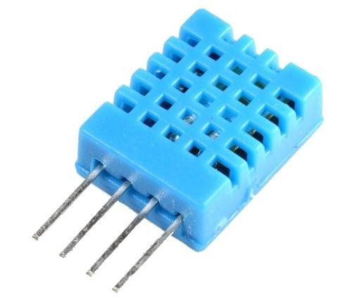
The DHT11 is a basic, ultra-low-cost digital temperature and humidity sensor. It uses a capacitive humidity sensor and a thermistor to measure the surrounding air and outputs a digital signal on the data pin. It’s simple to use but requires careful timing to grab data. It’s perfect for DIY projects, weather stations, and other applications where accurate and reliable temperature and humidity readings are needed.
Key Features:
- Temperature Range: 0-50°C with ±2°C accuracy
- Humidity Range: 20-80% RH with ±5% RH accuracy
- Low Power Consumption: Efficient for battery-operated applications
- Single Wire Digital Interface: Easy to interface with microcontrollers
- Pre-calibrated: No need for additional calibration
- Compact Size: Suitable for compact projects and devices
Technical Specifications:
- Temperature Range: 0-50°C (32-122°F)
- Humidity Range: 20-80% RH
- Temperature Accuracy: ±2°C
- Humidity Accuracy: ±5% RH
- Operating Voltage: 3.3V to 5.5V
- Max Current: 2.5mA
- Output: Digital signal via 1-wire protocol
- Dimensions: 15.5mm x 12mm x 5.5mm
Applications:
- Weather Stations: Monitor and log temperature and humidity levels.
- Home Automation: Control HVAC systems based on environmental conditions.
- Greenhouses: Maintain optimal growing conditions for plants.
- DIY Projects: Perfect for hobbyists building custom sensors and gadgets.
- Data Loggers: Record environmental data over time for analysis.
- Educational Projects: Teach students about sensors and data acquisition.
Usage:
- Wiring: Connect the VCC pin to 3.3V or 5V, GND to ground, and the DATA pin to a digital input on your microcontroller.
- Library Integration: Use libraries available for platforms like Arduino or Raspberry Pi to simplify reading data from the sensor.
- Coding: Write code to initialize the sensor and read temperature and humidity data.
- Data Processing: Process and use the sensor data in your application as needed, such as displaying it on an LCD or sending it to a web server.
Caution:
- Power Supply: Ensure the sensor is supplied with the correct voltage to avoid damage.
- Environmental Conditions: Keep the sensor in a dust-free, non-condensing environment for accurate readings.
- Wiring Length: Minimize the length of wiring between the sensor and the microcontroller to maintain signal integrity.
Datasheet:
For detailed technical specifications, refer to the DHT11 Datasheet.
|
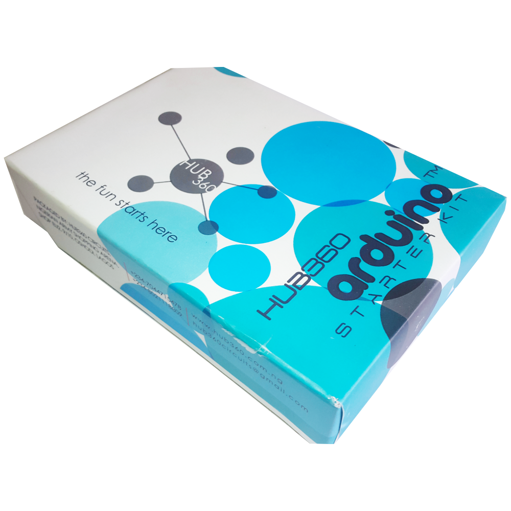
The Hub360 Arduino Starter Kit is a comprehensive package designed for beginners and enthusiasts looking to dive into the world of electronics and programming. This kit includes Arduino Uno, which is a microcontroller board based on the ATmega328P. The kit provides a variety of components and modules to help users learn and experiment with different electronic projects and concepts.
Key Features:
- Includes Arduino Uno board
- Comprehensive set of components and modules for various projects
- Ideal for beginners and hobbyists
- Detailed tutorial and project guide included
- USB interface for easy programming and power
- Compatible with Arduino IDE and various libraries
Technical Specifications:
- Microcontroller: ATmega328P
- Operating Voltage: 5V
- Input Voltage (recommended): 7-12V
- Digital I/O Pins: 14 (6 PWM outputs)
- Analog Input Pins: 6
- DC Current per I/O Pin: 20mA
- Flash Memory: 32KB (ATmega328P) of which 0.5KB used by bootloader
- SRAM: 2KB (ATmega328P)
- EEPROM: 1KB (ATmega328P)
- Clock Speed: 16 MHz
Kit Contents:
- ARDUINO BOARD 1
- ARDUINO USB CABLE 1
- ARDUINO BATTERY CONNECTOR 1
- 400 HOLE BREADBOARD 1
- LED (RED, YELLOW , GREEN, WHITE) 20
- RGB LED 1
- JUMPER WIRE(M-M, M-F, F-F) 120
- PHOTORESISTOR (LDR) 3
- MALE HEADERS 40
- ULTRASONIC SENSOR 1
- FLAME SENSOR 1
- TEMP./HUMIDITY SENSOR 1
- TILT SENSOR 1
- LASER SENSOR 1
- PIR MOTION SENSOR 1
- RESISTORS(220K, 1K, 10K,100K) 40
- 7 SEGMENT DISPLAY 1
- SG90 SERVO 1
- REMOTE CONTROL 1
- BUZZER 1
- 2N2222 2
- TSOP 1838 1
- RF TRANSMITTER 1
- RF RECEIVER 1
- TACT SWITCH 5
- 16*2 LCD DISPLAY
Applications:
- Learning basic electronics and programming
- Building interactive projects and prototypes
- Developing skills in microcontroller-based design
- Experimenting with sensors and actuators
- Creating DIY electronic devices
Usage:
- Setup:
- Connect the Arduino Uno board to your computer using the USB cable.
- Install the Arduino IDE and configure it to recognize the board.
- Programming:
- Write or upload sample code (sketches) to the Arduino board using the Arduino IDE.
- Utilize the provided components and modules to build and test different circuits.
- Experimentation:
- Follow the detailed tutorials and project guide to create various projects.
- Modify and expand on the sample projects to enhance learning and creativity.
Caution:
- Handle the components carefully to avoid damage.
- Ensure proper connections and polarity to prevent short circuits or component failure.
- Verify the code and circuit connections before powering the board.
Datasheet:
For detailed technical specifications of the Arduino Uno, refer to the Arduino Uno Datasheet.
|
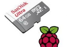
The Raspberry Pi SD Card 64GB is a high-capacity microSD card designed to provide ample storage for your Raspberry Pi projects. This microSD card offers a significant amount of space for operating systems, applications, data, and multimedia files, ensuring smooth and efficient performance. It is ideal for more complex and storage-intensive projects using any Raspberry Pi model with a microSD card slot.
Key Features:
- 64GB storage capacity
- Pre-loaded with the Raspberry Pi operating system (optional)
- High-speed data transfer rates
- Reliable and durable design
- Compatible with all Raspberry Pi models with a microSD card slot
- Ideal for projects requiring substantial storage space
- Easy to set up and use
Technical Specifications:
- Capacity: 64GB
- Format: MicroSDXC
- Speed Class: Class 10, UHS-I or UHS-II (varies by model)
- Read Speed: Up to 100MB/s (varies by model)
- Write Speed: Up to 90MB/s (varies by model)
- Operating Voltage: 2.7V to 3.6V
- Operating Temperature: -25°C to +85°C
- Storage Temperature: -40°C to +85°C
- Dimensions: Standard microSD card size
Applications:
- Raspberry Pi OS and application storage
- Data logging and storage
- Multimedia projects
- IoT applications
- Education and development projects
- Complex software development and testing
Datasheet:
For detailed technical information, please refer to the MicroSD Card Datasheet.
|
The Photoelectric Metal Sensor LJ12A34 is an industrial-grade proximity sensor designed to detect metal objects within a specified range. This sensor uses photoelectric technology to detect the presence of metallic items without making physical contact, making it ideal for applications where non-contact detection is essential. It is widely used in automation, manufacturing, robotics, and various industrial applications.
Key Features:
- Detection Method: Photoelectric proximity detection
- Sensing Distance: Up to 4mm for metallic objects
- Output Type: NPN normally open (NO)
- Operating Voltage: 6-36V DC
- Response Time: Fast response time for real-time detection
- Indicator: Built-in LED indicator for detection status
- Durability: Robust construction for industrial environments
- Installation: Easy mounting with threaded barrel design
Technical Specifications:
- Dimensions:
- Sensor Diameter: 12 mm
- Length: 60 mm
- Weight: Approximately 30 g
- Sensing Distance: 4 mm (for iron)
- Output Current: 300 mA max
- Operating Temperature: -25°C to +70°C
- Humidity: 35% to 95% RH
- Response Frequency: 1 kHz
- Material: Metal housing with plastic sensing face
- Cable Length: 1.2 meters
Applications:
- Automation: Used in automated systems to detect the presence of metal parts.
- Manufacturing: Ideal for production lines to ensure the correct placement of metal components.
- Robotics: Used in robots for object detection and avoidance.
- Safety Systems: Integrated into safety systems to detect the presence or absence of metal objects.
- Quality Control: Helps in quality control processes by detecting metal parts during manufacturing.
Datasheet:
For detailed technical information, refer to the Photoelectric Metal Sensor LJ12A34 Datasheet.
|
The Allen key, also known as a hex key or hex wrench, is a small hand tool used to drive screws and bolts with hexagonal sockets. The Size 4 mm Allen key is designed to fit fasteners with a 4 mm hexagonal socket. This tool is commonly used in various mechanical, electrical, and DIY applications.
Key Features:
- Size: 4 mm (hexagonal socket size)
- Shape: L-shaped or T-shaped
- Material: Typically made from steel or chrome vanadium for durability and strength
- Finish: Often coated with black oxide or chrome plating for corrosion resistance
- Type: Can come in various designs such as short or long arm, ball-end, or standard
Technical Specifications:
- Hexagon Size: 4 mm
- Length: Varies depending on design (e.g., 60 mm to 150 mm for short arm, longer for T-handle or L-handle)
- Material: Steel, chrome vanadium, or other hardened materials
- Finish: Black oxide, chrome-plated, or other protective coatings
Applications:
- Mechanical Work: Used in automotive repair, machinery assembly, and other mechanical tasks.
- Furniture Assembly: Commonly used for assembling flat-pack furniture.
- Bicycles: Used for adjusting and tightening components on bicycles.
- Electronics: Helpful in assembling and repairing electronic devices with hex screws.
- DIY Projects: Essential for various home improvement and hobbyist tasks.
Datasheet:
Typically, Allen keys do not have detailed datasheets, but specifications can be obtained from this datasheet.
|
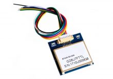
The VK2828 G28U7FTTL is a high-performance GPS module designed for aviation and other high-precision applications. It features a wide range of operational frequencies and is capable of delivering accurate positional data for navigation and tracking purposes. The module is ideal for integration into systems requiring reliable and precise GPS information.
Key Features:
- High Update Rate: Capable of updating position data from 1Hz to 10Hz, allowing for smooth and accurate tracking
- Sensitivity: Designed for use in aviation, providing robust performance in various environmental conditions
- Compatibility: Supports standard GPS protocols for easy integration into existing systems
- Compact Size: Suitable for integration into space-constrained applications
Technical Specifications:
- Type: GPS Module
- Model: VK2828 G28U7FTTL
- Update Rate: 1Hz to 10Hz
- Frequency Range: Supports standard GPS frequencies
- Sensitivity: High sensitivity for accurate positioning
- Protocol: NMEA-0183
- Operating Voltage: Typically 3.3V to 5V DC
- Power Consumption: Low power consumption for battery-operated applications
- Dimensions: Varies by model, generally compact for easy integration
- Antenna: May include an external or integrated antenna depending on the model
Applications:
- Aviation: Navigation and tracking for aircraft
- Marine: Boat and ship navigation
- Automotive: Advanced driver-assistance systems (ADAS)
- Outdoor Activities: Hiking and sports tracking
- Industrial: Asset tracking and fleet management
Usage:
- Powering the Module: Connect the GPS module to a suitable power source within the specified voltage range.
- Connecting the Antenna: Ensure the antenna is properly connected and positioned for optimal signal reception.
- Data Integration: Use the NMEA protocol to receive GPS data, including latitude, longitude, altitude, and time.
- Integration: Connect the GPS module to your system or application for real-time tracking and navigation.
Caution:
- Signal Reception: Ensure the module has a clear view of the sky for optimal GPS signal reception.
- Voltage: Verify the operating voltage to avoid damage to the module.
- Antenna Placement: Position the antenna to minimize interference and maximize signal strength.
Datasheet:
For detailed technical specifications, refer to the VK2828 G28U7FTTL Datasheet .
|
The LiPo Battery 7.4V 2400mAh is a rechargeable lithium polymer battery commonly used in high-performance applications such as drones, RC vehicles, and other electronics. Its high capacity and stable voltage make it suitable for applications requiring reliable and extended power supply. This battery offers a balance between size, weight, and power output.
Key Features:
- Voltage: 7.4V (nominal)
- Capacity: 2400mAh
- Chemistry: Lithium Polymer (LiPo)
- Discharge Rate: Typically high discharge rates available (e.g., 20C to 30C)
- Charge Rate: Safe charging rate, typically 1C (2400mA)
- Compact Design: Lightweight and compact for easy integration
- Protection Circuit: Often includes built-in protection to prevent overcharging and over-discharging (varies by manufacturer)
Technical Specifications:
- Dimensions:
- Length: 100 mm (typical)
- Width: 35 mm (typical)
- Height: 15 mm (typical)
- Weight: Approximately 150 g
- Nominal Voltage: 7.4V
- Capacity: 2400mAh
- Discharge Rate:
- Continuous: Typically 20C to 30C (e.g., 48A to 72A)
- Peak: Higher rates available depending on model
- Charge Rate: 1C (2400mA) or as specified by manufacturer
- Connector Type: JST or XT60 (varies by model)
- Battery Type: Lithium Polymer (LiPo)
- Protection Circuit: Built-in protection (varies by model)
Applications:
- Drones: Provides power for multirotor drones and other UAVs.
- RC Vehicles: Suitable for remote-controlled cars, boats, and planes.
- Electronics Projects: Ideal for DIY electronics and prototyping projects requiring reliable power.
- High-Power Devices: Used in devices requiring high discharge rates and extended battery life.
Datasheet:
For detailed technical information, refer to the LiPo Battery 7.4V 2400mAh Datasheet.
|
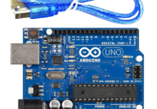
The Arduino Uno R3 is a popular microcontroller board based on the ATmega328P. It is designed for easy integration into a wide range of applications, from hobby projects to professional prototyping. The board features a comprehensive set of I/O pins, communication interfaces, and power options, making it ideal for learning, experimentation, and development of embedded systems.
Key Features:
- Microcontroller: ATmega328P
- 14 Digital I/O Pins (6 PWM outputs)
- 6 Analog Input Pins
- Clock Speed: 16 MHz
- USB connection for programming and power
- 32KB Flash Memory (0.5KB used by bootloader)
- 2KB SRAM and 1KB EEPROM
- Built-in Power LED
- Supports SPI, I2C, and UART communication
Technical Specifications:
- Microcontroller: ATmega328P
- Operating Voltage: 5V
- Input Voltage (recommended): 7-12V
- Input Voltage (limits): 6-20V
- Digital I/O Pins: 14 (of which 6 provide PWM output)
- Analog Input Pins: 6
- DC Current per I/O Pin: 20 mA
- DC Current for 3.3V Pin: 50 mA
- Flash Memory: 32 KB (ATmega328P) of which 0.5 KB used by bootloader
- SRAM: 2 KB (ATmega328P)
- EEPROM: 1 KB (ATmega328P)
- Clock Speed: 16 MHz
- USB Connector: Type B
- Dimensions: 68.6 mm x 53.4 mm
- Weight: 25 g
Applications:
- Embedded system prototyping
- DIY electronics projects
- Educational tools for learning programming and electronics
- Robotics
- IoT (Internet of Things) devices
- Automation and control systems
Usage:
- Programming:
- Connect the Arduino Uno R3 to your computer using a USB cable.
- Open the Arduino IDE and select the board and correct COM port.
- Write your program (sketch) and upload it to the board.
- Powering:
- The board can be powered via the USB connection or with an external power supply (7-12V recommended).
- External power can be supplied through the power jack or via the Vin pin.
- Interfacing:
- Use the digital and analog I/O pins to connect sensors, actuators, and other components.
- Utilize communication interfaces like SPI, I2C, and UART for connecting to other devices and modules.
Caution:
- Avoid exceeding the maximum current ratings to prevent damage to the board.
- Ensure proper handling to avoid static discharge which can damage the microcontroller.
- Use a proper power supply to avoid over-voltage damage.
Datasheet:
For detailed technical specifications, refer to the Arduino Uno R3 Datasheet.
|
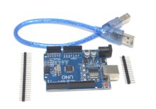
- The Arduino UNO R3 SMD is a popular and versatile microcontroller board based on the ATmega328P microcontroller. The SMD (Surface-Mount Device) version features the ATmega328P microcontroller in an SMD package, offering the same functionality as the traditional UNO R3 but with a more compact design. It is widely used for a variety of projects, from simple experiments to complex prototypes.
Key Features:
- Microcontroller: ATmega328P in SMD package
- Operating Voltage: 5V
- Input Voltage (recommended): 7-12V
- Digital I/O Pins: 14 (of which 6 provide PWM output)
- Analog Input Pins: 6
- Flash Memory: 32 KB (ATmega328P) of which 0.5 KB used by bootloader
- SRAM: 2 KB (ATmega328P)
- EEPROM: 1 KB (ATmega328P)
- Clock Speed: 16 MHz
- USB Connection: Standard USB-B for programming and communication
- Power Jack: 2.1mm center-positive barrel jack
- ICSP Header: For in-circuit programming
- Reset Button: For easy reset of the microcontroller
Technical Specifications:
- Microcontroller: ATmega328P
- Operating Voltage: 5V
- Input Voltage (limits): 6-20V
- Digital I/O Pins: 14 (6 PWM)
- PWM Digital I/O Pins: 6
- Analog Input Pins: 6
- DC Current per I/O Pin: 20 mA
- DC Current for 3.3V Pin: 50 mA
- Flash Memory: 32 KB (ATmega328P) of which 0.5 KB used by bootloader
- SRAM: 2 KB (ATmega328P)
- EEPROM: 1 KB (ATmega328P)
- Clock Speed: 16 MHz
- Length: 68.6 mm
- Width: 53.4 mm
- Weight: 25 g
Applications:
- Educational Projects: Ideal for beginners and students learning electronics and programming.
- Prototyping: Widely used for developing and testing new electronic devices and systems.
- Robotics: Can be used as a controller for various robotics projects.
- Home Automation: Suitable for creating smart home devices and automation systems.
- DIY Projects: Perfect for hobbyists and makers building custom gadgets and interactive installations.
Datasheet:
For detailed technical specifications, refer to the Arduino UNO R3 SMD Datasheet.
|
A set of male-female jumper wires includes multiple wires, each with a male connector on one end and a female connector on the other. These wires are commonly used in electronic prototyping and development to establish connections between components, breadboards, and circuit boards. The set typically comes in a variety of lengths and colors, making it versatile and easy to manage for various project needs.
Key Features:
- Connectors: Male connector on one end and female connector on the other
- Wire Type: Flexible, insulated wire for easy routing and manipulation
- Length Options: Set often includes wires of various lengths to suit different applications
- Color-Coded: Available in multiple colors for easy identification and organization
- Durability: High-quality materials for reliable and repeated use
- Compatibility: Fits standard 2.54mm (0.1 inch) pitch headers and connectors
Technical Specifications:
- Connector Type: Male-to-female
- Wire Gauge: Typically 28 AWG
- Insulation Material: PVC or similar flexible plastic
- Pitch: 2.54mm (0.1 inch)
- Length Options: Common lengths in the set may include 10cm, 20cm, 30cm, etc.
- Operating Temperature: Typically -40°C to +80°C
- Current Rating: Usually up to 1A
Applications:
- Prototyping: Ideal for creating and modifying circuits on breadboards and development boards.
- Educational Projects: Used for teaching and learning electronics and programming.
- DIY Electronics: Perfect for hobbyists working on various electronics projects and experiments.
- Temporary Connections: Useful for making temporary connections during the development and testing phases.
- Interfacing Modules: Facilitates connections between male pin headers and female sockets on different electronic modules and components.
|
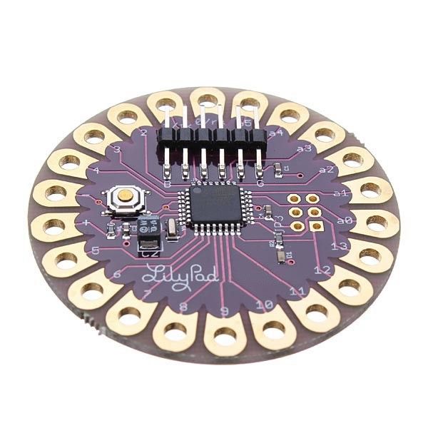
The Arduino LilyPad is a flexible and washable microcontroller board designed for e-textiles and wearable electronics. It is part of the Arduino platform and features a unique design that allows it to be integrated into fabric and clothing. The LilyPad is ideal for projects that require electronic components to be embedded in textiles, enabling creative and interactive wearable technology.
Key Features:
- Microcontroller: ATmega328P, similar to Arduino Uno
- Flexible Design: Can be sewn into fabric or clothing
- Washable: Water-resistant design for washable applications (note: always check the specific model’s washing instructions)
- Connectivity: Includes a range of I/O pins for connecting sensors, actuators, and other components
- Power Supply: Can be powered via USB or external battery pack
- Programming: Compatible with the Arduino IDE for easy programming
Technical Specifications:
- Dimensions:
- Weight: Approximately 10 g
- Operating Voltage: 2.7V to 5.5V DC
- Digital I/O Pins: 14 (of which 6 provide PWM output)
- Analog Input Pins: 6
- Flash Memory: 32 KB (ATmega328P) of which 0.5 KB used by bootloader
- SRAM: 2 KB (ATmega328P)
- EEPROM: 1 KB (ATmega328P)
- Clock Speed: 16 MHz
- Communication: UART, SPI, I2C
- Power Supply: Can be powered via USB or battery (battery not included)
- Connector Types: Sewable conductive thread or wire for connections
Applications:
- Wearable Technology: Ideal for creating interactive clothing and accessories.
- E-Textiles: Used in smart fabrics and textiles for embedded electronics.
- Education: Useful for teaching electronics and programming in a hands-on manner.
- DIY Projects: Perfect for hobbyists creating custom wearable gadgets.
- Interactive Art: Enables the creation of art installations that involve electronics and textiles.
Datasheet:
For detailed technical information, refer to the Arduino LilyPad Datasheet.
|
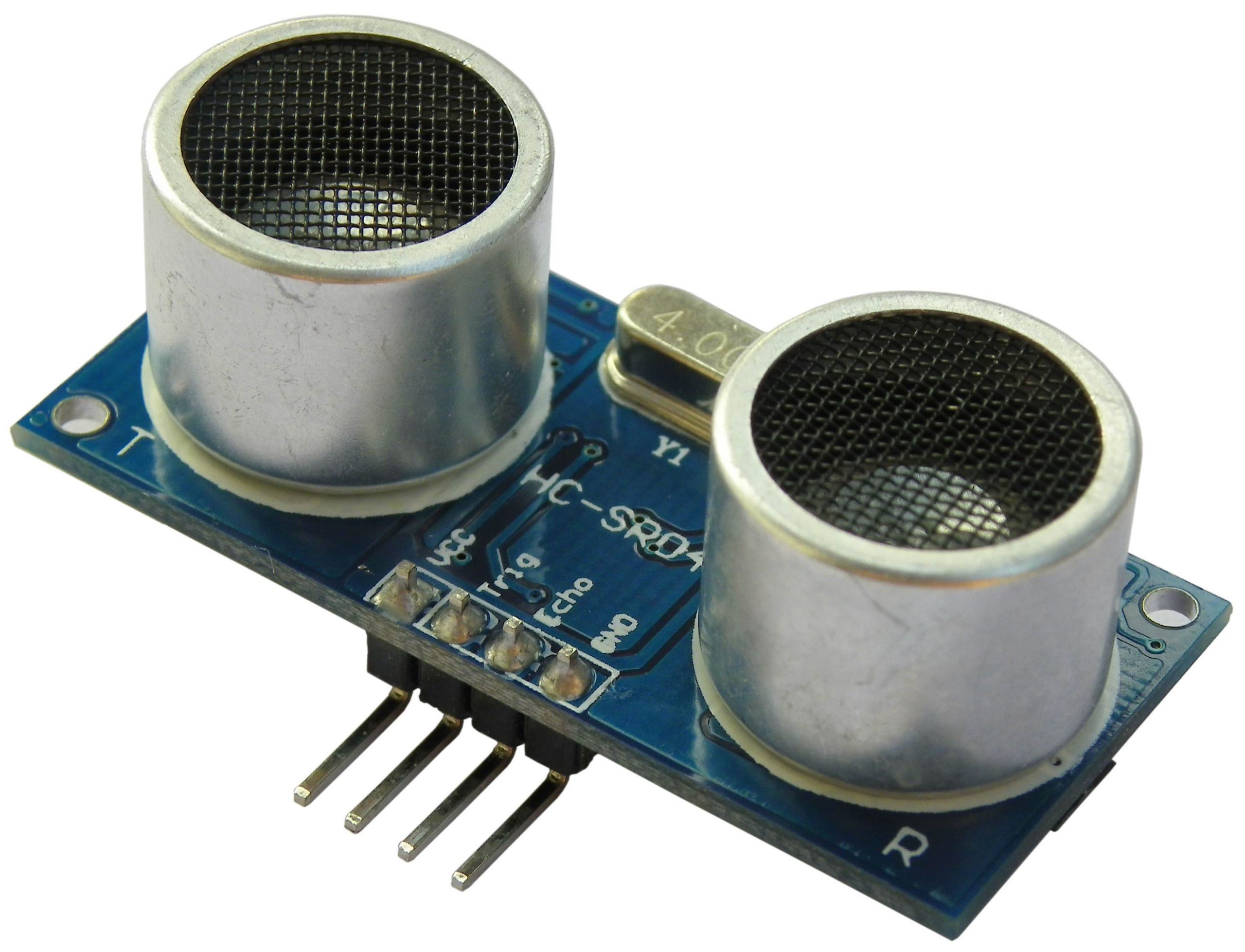
The HC-SR04 is an affordable and easy-to-use ultrasonic distance sensor. It measures the distance to an object by using sonar technology and provides accurate distance measurements from 2 cm to 400 cm. The sensor is widely used in robotics, obstacle avoidance systems, and various DIY electronics projects.
Key Features:
- Ultrasonic ranging module
- High precision and stable performance
- Simple pulse-in/pulse-out communication
- Measurement range: 2 cm to 400 cm
- Accurate to ±3 mm
- Low power consumption
- Easy integration with microcontrollers (Arduino, Raspberry Pi, etc.)
Technical Specifications:
- Operating Voltage: 5V DC
- Quiescent Current: < 2 mA
- Working Current: 15 mA
- Measurement Range: 2 cm to 400 cm
- Resolution: 1 cm
- Measuring Angle: 15 degrees
- Trigger Input Pulse Width: 10 µs
- Echo Pulse Width: Proportional to distance
- Dimensions: 45mm x 20mm x 15mm
Applications:
- Obstacle avoidance systems
- Distance measuring
- Object detection
- Autonomous navigation for robots
- Liquid level measurement
- Proximity sensing
Usage:
- Connection:
- Connect the VCC pin to a 5V power supply.
- Connect the GND pin to ground.
- Connect the Trig (Trigger) pin to a digital output pin on the microcontroller.
- Connect the Echo pin to a digital input pin on the microcontroller.
- Operation:
- To initiate a measurement, send a 10 µs high pulse to the Trig pin.
- The sensor will emit an 8-cycle burst of ultrasound at 40 kHz and set the Echo pin high.
- Measure the duration for which the Echo pin remains high to calculate the distance to the object (distance = duration * 0.034 / 2).
- Programming:
- Write a program on the microcontroller to send the trigger pulse, read the echo pulse duration, and calculate the distance.
- Many microcontroller platforms, such as Arduino, have libraries available to simplify interfacing with the HC-SR04.
Caution:
- Avoid using the sensor in environments with excessive noise or strong ultrasonic interference.
- Handle the sensor with care to avoid damage to the ultrasonic transducers.
- Ensure proper connections to avoid incorrect readings or damage to the sensor.
Datasheet:
For detailed technical specifications, refer to the HC-SR04 Datasheet.
|
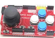
The Joystick Shield V1 is an expansion board designed for Arduino and other compatible microcontroller platforms. It features a joystick, buttons, and connectors that enable easy interfacing for a variety of applications, including gaming, robotics, and interactive projects. The shield provides an intuitive and user-friendly interface for controlling movements and actions in your projects.
Key Features:
- Analog Joystick: Two-axis joystick for precise control of movement.
- Push Buttons: Includes multiple push buttons for additional input options.
- Shield Design: Easily stackable on top of Arduino boards, maintaining a compact form factor.
- Plug and Play: Simple to connect and start using with minimal setup required.
- Versatile Applications: Suitable for gaming controllers, robotic controls, and interactive systems.
Technical Specifications:
- Joystick: 2-axis (X and Y) analog joystick with a push-button function
- Buttons: 5 push buttons (up, down, left, right, select)
- Interface: Connects to Arduino through the standard shield interface
- Operating Voltage: 5V (supplied by the Arduino board)
- Dimensions: Compatible with standard Arduino board dimensions
Applications:
- Gaming Controllers: Create custom gaming controllers for various platforms.
- Robotics: Use the joystick and buttons to control robotic movements and actions.
- Interactive Projects: Develop interactive installations and projects that require user input.
- Prototyping: Ideal for quickly testing and prototyping control interfaces.
Datasheet:
For detailed technical specifications, refer to the Joystick Shield V1 Datasheet.
|
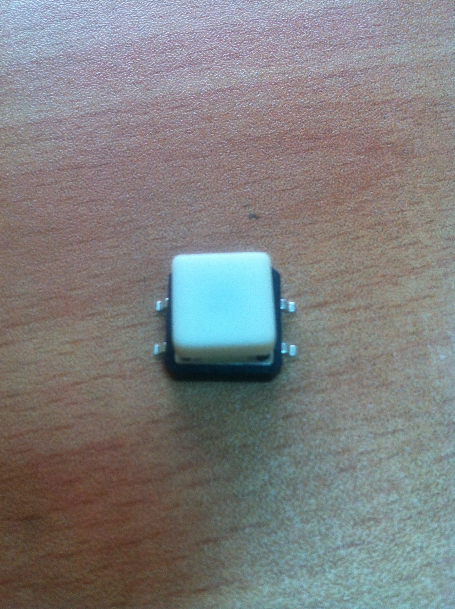
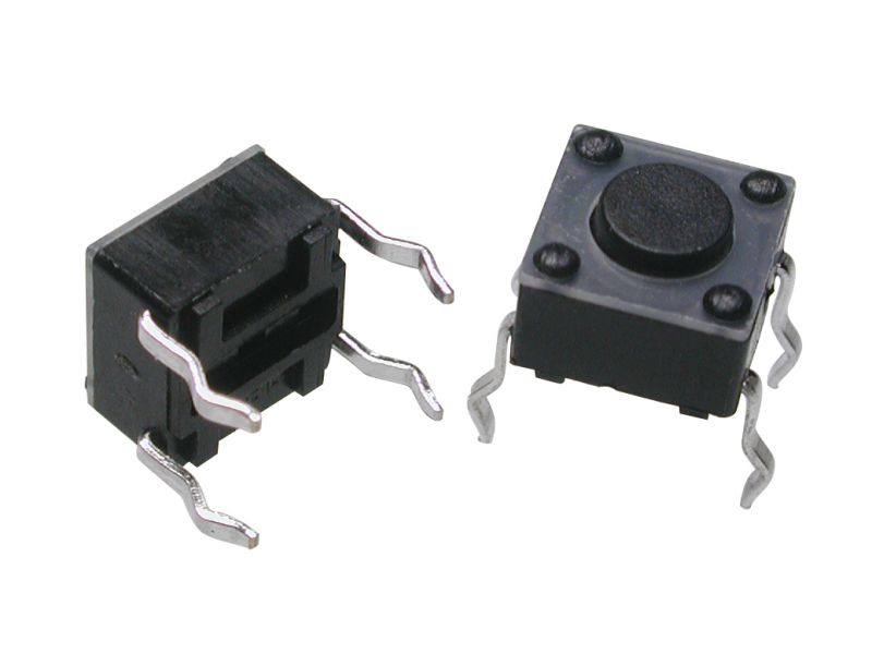
The SMD (Surface-Mount Device) tact switch with cap is a compact, reliable switch used in various electronic devices and applications. The switch is mounted directly onto a printed circuit board (PCB) and is designed to be activated by pressing the cap. The cap provides a user-friendly interface and helps in guiding the pressing action.
Key Features:
- Type: SMD Tactile Switch
- With Cap: Includes a cap for easy pressing and improved tactile feedback
- Mounting Type: Surface-mount for easy PCB integration
- Actuation Force: Typically designed for low actuation force
- Switch Function: Momentary contact (normally open; closes when pressed)
- Durability: Designed for many cycles of operation
Technical Specifications:
- Package Type: SMD (Surface-Mount Device)
- Cap Type: Plastic or rubber cap for tactile feedback
- Actuation Force: Typically ranges from 100g to 500g (varies by model)
- Contact Rating: Generally rated for 50mA to 100mA at 12V (varies by model)
- Contact Resistance: Typically 100Ω or less
- Insulation Resistance: Typically 100MΩ or more
- Life Cycle: Rated for up to 1,000,000 cycles
- Operating Temperature Range: -20°C to +85°C
Applications:
- Consumer Electronics: Used in devices like remote controls, calculators, and handheld devices
- Industrial Equipment: Integrated into control panels and user interfaces
- Automotive: Utilized in dashboards and control systems
- Medical Devices: Employed in compact medical equipment and interfaces
Usage:
- PCB Mounting: Solder the SMD tact switch to the designated pads on the PCB.
- Cap Placement: Ensure the cap is securely placed on the switch for proper operation and tactile feedback.
- Testing: Test the switch to ensure it functions correctly and provides the desired tactile response.
- Integration: Integrate the switch into the final assembly and connect it to the necessary circuits or components.
Caution:
- Handling: Handle with care to avoid damaging the switch or cap.
- Soldering: Follow proper soldering techniques to avoid overheating or damaging the switch.
- Compatibility: Ensure the switch is compatible with the design requirements and PCB layout.
Datasheet:
For detailed technical specifications and mounting guidelines, refer to the manufacturer’s datasheet for the specific SMD tact switch model.
|
The Wemos D1 WiFi UNO is a microcontroller development board that combines the features of the popular Arduino UNO with built-in WiFi capabilities, thanks to the integration of the ESP8266 module. It is designed for IoT (Internet of Things) applications, enabling easy connection to WiFi networks and interaction with cloud services or other devices over the internet.
Key Features:
- Compatible with Arduino IDE for ease of development
- Built-in WiFi connectivity via ESP8266 module
- Microcontroller based on the ESP8266 chip
- USB interface for programming and power
- 11 digital I/O pins, including 1 PWM output
- 1 analog input
- Onboard LED and reset button
- Compact design suitable for various applications
Technical Specifications:
- Microcontroller: ESP8266
- Operating Voltage: 3.3V DC
- WiFi Connectivity: 802.11 b/g/n
- Digital I/O Pins: 11
- PWM Outputs: 1
- Analog Input: 1 (0-1V range)
- Flash Memory: 4 MB (typically)
- Clock Speed: 80 MHz or 160 MHz
- Package Type: Standard Arduino UNO layout
- Dimensions: Approximately 68mm x 53mm
Applications:
- Internet of Things (IoT) projects
- Home automation systems
- Wireless data logging
- Remote sensor monitoring
- Smart home devices
- Educational projects in electronics and programming
Usage:
- Connect the Wemos D1 WiFi UNO to your computer via the USB interface.
- Install the necessary drivers and Arduino IDE with the ESP8266 board support package.
- Write and upload your code using the Arduino IDE, leveraging the WiFi capabilities to connect to networks or web services.
- Use the digital I/O pins, analog input, and onboard LED in your projects according to your needs.
- Monitor and debug your project using serial output or other communication methods.
Caution:
- Ensure proper USB connection and avoid overvoltage to prevent damage.
- Follow the WiFi module’s usage guidelines for optimal performance and connectivity.
- Handle with care to avoid damage to the onboard components.
Datasheet:
For detailed technical specifications, refer to the Wemos D1 WiFi UNO Datasheet.
|
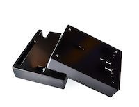
The ABS Arduino Uno Casing is a robust and durable enclosure designed to protect the Arduino Uno microcontroller board. Made from high-quality ABS plastic, this casing provides a secure and attractive housing for your projects, shielding the Arduino board from dust, moisture, and physical damage. The design includes pre-cut openings for all the necessary ports and connectors, ensuring easy access to the board’s features while keeping it protected.
Key Features:
- Made from high-quality ABS plastic for durability and strength
- Pre-cut openings for USB, power, and I/O ports
- Secure snap-fit design for easy assembly and disassembly
- Provides protection from dust, moisture, and physical damage
- Transparent or opaque options available
- Lightweight and compact design
Technical Specifications:
- Material: ABS Plastic
- Compatibility: Arduino Uno R3
- Dimensions: Approximately 79mm x 60mm x 21mm
- Weight: Approximately 25g
- Color Options: Transparent, Black, White, Blue (varies by supplier)
- Mounting: Snap-fit design with screw holes for additional security
Applications:
- Housing for Arduino Uno projects
- Educational and prototyping applications
- DIY electronics projects
- Protecting Arduino Uno in harsh environments
- Displaying and showcasing Arduino-based projects
Usage:
- Place the Arduino Uno board into the bottom half of the ABS casing, ensuring that the ports align with the pre-cut openings.
- Snap the top half of the casing onto the bottom half, ensuring a secure fit.
- Optionally, use screws to further secure the two halves if provided.
- Connect the necessary cables and peripherals through the openings, and proceed with your project as usual.
Caution:
- Ensure that all connections are properly aligned and secure before use.
- Avoid exposure to extreme temperatures or harsh chemicals that could damage the ABS material.
- Handle with care to prevent cracking or damaging the plastic casing.
Datasheet:
For detailed technical specifications, refer to the ABS Arduino Uno Casing Datasheet.
|
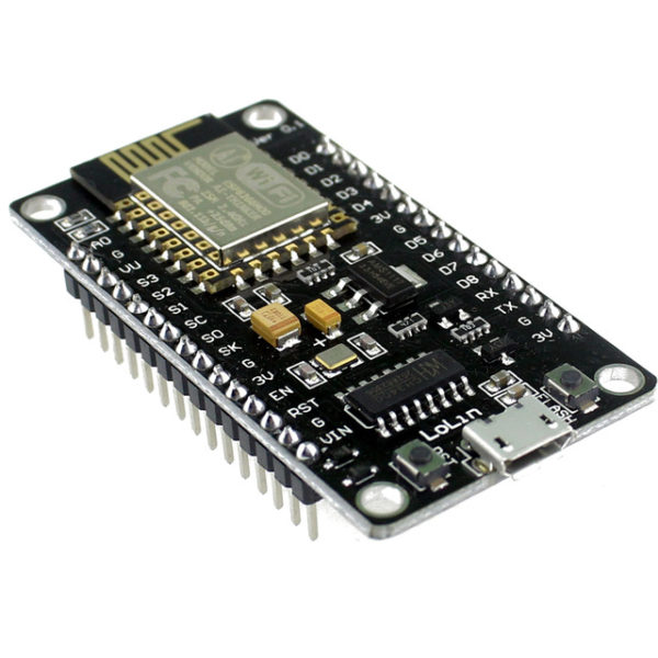
The ESP8266 NodeMcu LUA WiFi Development Board is an open-source IoT platform. It integrates the ESP8266 WiFi module, which allows for easy development of WiFi-based applications. The board includes the Lua scripting language for programming, enabling quick and efficient development. This development board is highly suitable for beginners and professionals looking to build IoT projects due to its simplicity, low cost, and robust capabilities.
Key Features:
- WiFi Module: Integrated ESP8266 with full TCP/IP stack and microcontroller capability
- Programming Language: Lua scripting language support
- GPIO: Multiple GPIO pins available for connecting sensors and actuators
- USB Interface: On-board USB to serial interface for easy programming
- Memory: 4MB Flash Memory
- Power Supply: Can be powered via micro USB or external power supply
- Built-in Antenna: On-board WiFi antenna for wireless connectivity
- Compact Size: Small form factor for easy integration into projects
Technical Specifications:
- Dimensions: 48 mm x 26 mm
- Weight: Approximately 10 g
- Operating Voltage: 3.3V
- Digital I/O Pins: 11
- Analog Input Pins: 1 (max input 3.2V)
- Clock Speed: 80 MHz
- Flash Memory: 4MB
- USB to UART: CP2102 or CH340G
- Power Consumption:
- Deep Sleep: <10 μA
- Light Sleep: <1 mA
- Modem Sleep: ~15 mA
- Active Mode: ~70 mA
- WiFi Standards: 802.11 b/g/n
- Connector Types: Micro USB, GPIO headers
Applications:
- IoT Projects: Ideal for developing Internet of Things applications with WiFi connectivity.
- Home Automation: Control and monitor home appliances and systems remotely.
- Prototyping: Rapid development and testing of WiFi-enabled prototypes.
- Wireless Sensor Networks: Creating networks of sensors with real-time data collection and communication.
- Smart Devices: Integrating WiFi capabilities into various smart devices and gadgets.
Datasheet:
For detailed technical information, refer to the ESP8266 NodeMcu LUA WiFi Development Board Datasheet.
|
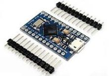
The Arduino Pro Micro is a compact and versatile microcontroller board based on the ATmega32U4 microchip. It is part of the Arduino family and designed for projects where space is limited. The Pro Micro board features built-in USB capabilities, allowing it to emulate a keyboard, mouse, or other USB devices, making it suitable for a wide range of applications including custom input devices and embedded systems.
Key Features:
- Microcontroller: ATmega32U4
- Operating Voltage: 5V
- Input Voltage (recommended): 7-12V
- Digital I/O Pins: 18
- Analog Input Pins: 9
- Flash Memory: 32 KB (ATmega32U4), of which 4 KB used by bootloader
- SRAM: 2.5 KB
- EEPROM: 1 KB
- Clock Speed: 16 MHz
- USB: Built-in USB functionality for direct connection to computers and emulation of USB devices
Technical Specifications:
- Dimensions: 33 mm x 18 mm
- Weight: Approximately 8 g
- Communication: UART, SPI, I2C, USB
- On-board LEDs: TX, RX, Power, and one user-defined LED
- Power:
- DC Current per I/O Pin: 40 mA
- DC Current for 3.3V Pin: 50 mA
- Connectors:
- USB Micro-B for programming and power
- 6-pin header for serial communication
- Pins for additional communication interfaces and power
Applications:
- Custom Input Devices: Can be used to create custom keyboards, mice, and other input devices.
- Embedded Systems: Suitable for small-scale embedded projects where USB connectivity is required.
- Prototyping: Ideal for rapid prototyping and development due to its compact size and USB capability.
- IoT Projects: Can be integrated into Internet of Things (IoT) devices for various control and monitoring applications.
- Wearables: Perfect for wearable electronics and projects requiring a small form factor.
Datasheet:
For detailed technical information, refer to the Arduino Pro Micro Datasheet.
|
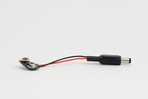
The Arduino 9V Battery Connector is a convenient accessory for powering Arduino boards and other compatible devices. It allows you to connect a standard 9V battery to the Arduino’s power jack, providing a portable power solution for your projects. This connector is essential for mobile and battery-operated applications, offering an easy and reliable way to supply power to your electronics.
Key Features:
- Compatible with standard 9V batteries
- Easy to connect and use
- Provides a secure and stable power connection
- Compact and portable design
- Durable construction for long-lasting use
- Standard DC barrel plug compatible with Arduino boards
Technical Specifications:
- Connector Type: DC barrel plug (center-positive)
- Barrel Plug Dimensions: Outer diameter 5.5mm, inner diameter 2.1mm
- Battery Connector Type: Snap-on connector for 9V battery
- Cable Length: Approximately 15 cm
- Material: Plastic and metal connectors with insulated wire
- Color: Typically black with red and black wires
Applications:
- Portable Arduino projects
- Battery-operated electronics
- Prototyping and testing
- Educational kits
- DIY electronics
Usage:
- Connection:
- Snap the 9V battery connector onto the terminals of a standard 9V battery.
- Insert the DC barrel plug into the power jack of your Arduino board or compatible device.
- Powering:
- Ensure the polarity of the connections is correct (center-positive) to avoid damage to the board.
- The Arduino will draw power from the 9V battery through the connector.
- Monitoring:
- Monitor the battery voltage periodically to ensure it remains within the acceptable range for your Arduino board (typically 7-12V).
Caution:
- Ensure the connector is securely attached to the battery terminals to prevent intermittent connections.
- Avoid short-circuiting the battery terminals.
- Do not expose the connector to moisture or extreme temperatures.
- Remove the battery from the connector when not in use to prevent battery drain.
Datasheet:
Refer to the manufacturer’s guidelines or specifications for further details.
|
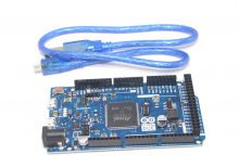
Description: The Arduino Due R3 is a powerful 32-bit microcontroller board based on the ARM Cortex-M3 processor. It offers enhanced performance and greater capabilities compared to earlier Arduino boards, making it ideal for complex projects that require advanced computing power and high-speed processing. The board features a large number of digital and analog I/O pins, along with built-in peripherals and communication interfaces, providing flexibility for a wide range of applications.
Key Features:
- Based on the 32-bit ARM Cortex-M3 processor
- 54 digital I/O pins, 12 analog inputs, and 4 UARTs
- 84 MHz clock speed for high-speed operation
- 512 KB Flash memory and 96 KB SRAM
- USB OTG (On-The-Go) and Native USB support
- Compatible with the Arduino IDE for easy programming
Technical Specifications:
- Microcontroller: Atmel SAM3X8E (ARM Cortex-M3)
- Operating Voltage: 3.3V
- Input Voltage: 7V to 12V
- Digital I/O Pins: 54
- Analog Inputs: 12
- Flash Memory: 512 KB
- SRAM: 96 KB
- Clock Speed: 84 MHz
- USB Interfaces: USB OTG, Native USB
- Dimensions: 101.6 mm x 53.3 mm
Applications:
- Advanced robotics
- Complex sensor integration
- High-speed data processing
- Industrial control systems
- DIY electronics projects requiring high processing power
Datasheet: For detailed technical information, refer to the Arduino Due R3 32-bit ARM Board Datasheet.
|
The Arduino Uno R4 WiFi is an advanced version of the popular Arduino Uno microcontroller board. It is based on the ATmega328P and includes integrated WiFi capabilities, making it ideal for IoT projects and wireless communication applications. The Uno R4 WiFi retains the ease of use and versatility of the original Uno, while adding wireless connectivity and enhanced performance.
Key Features:
- Microcontroller: ATmega328P
- Operating Voltage: 5V
- Input Voltage (recommended): 7-12V
- Input Voltage (limit): 6-20V
- Digital I/O Pins: 14 (of which 6 provide PWM output)
- Analog Input Pins: 6
- Flash Memory: 32 KB (ATmega328P) of which 0.5 KB used by bootloader
- SRAM: 2 KB (ATmega328P)
- EEPROM: 1 KB (ATmega328P)
- Clock Speed: 16 MHz
- WiFi: Integrated WiFi module for wireless connectivity
- USB Connection: For programming and power
Technical Specifications:
- Dimensions: 68.6 mm x 53.4 mm
- Weight: 25 g
- Communication: UART, SPI, I2C, WiFi
- On-board LEDs: TX, RX, Power, and Pin 13
- Power:
- DC Current per I/O Pin: 20 mA
- DC Current for 3.3V Pin: 50 mA
- Connectors:
- USB-B for programming and power
- Barrel jack for external power supply
- ICSP header for in-circuit programming
- 6-pin header for additional communication interfaces
- WiFi Specifications:
- Frequency: 2.4 GHz
- Protocols: IEEE 802.11 b/g/n
- Security: WEP, WPA, WPA2
Applications:
- Education: Ideal for teaching and learning electronics, programming, and IoT.
- Prototyping: Suitable for developing and testing new electronic projects with wireless connectivity.
- DIY Projects: Perfect for hobbyists creating custom gadgets, robots, and interactive installations with WiFi capabilities.
- IoT Projects: Can be used to build Internet of Things (IoT) applications by connecting sensors and actuators to the internet.
- Embedded Systems: Useful for designing and implementing embedded systems with wireless communication.
Datasheet:
For detailed technical information, refer to the Arduino Uno R4 WiFi Datasheet.
Manufacturer: Arduino
|
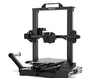
The Creality CR-6SE is a high-precision 3D printer designed for users seeking reliable, professional-quality prints. Known for its ease of use and innovative features, the CR-6SE offers an enhanced printing experience with a focus on accuracy, stability, and user convenience. Ideal for hobbyists, educators, and professionals, this 3D printer delivers excellent performance for a variety of projects, from prototypes to complex models.
Key Features:
- High Precision Printing: Delivers detailed and accurate prints with a layer resolution of 0.1 mm.
- Auto-Leveling System: Features an advanced leveling-free system for hassle-free setup.
- Silent Operation: Equipped with a silent motherboard and TMC2209 drivers for quiet printing.
- Sturdy Construction: Built with a robust aluminum frame for stability and durability.
- Modular Design: Easy to assemble and maintain with a modular design.
- Resume Printing Function: Capable of resuming printing after power outages or interruptions.
- Touch Screen Interface: 4.3-inch color touch screen for an intuitive user interface.
- Dual Z-Axis: Provides improved accuracy and stability for the Z-axis movement.
Technical Specifications:
- Build Volume: 235 x 235 x 250 mm
- Layer Resolution: 0.1 mm
- Printing Speed: Up to 100 mm/s
- Nozzle Diameter: Standard 0.4 mm (interchangeable)
- Filament Compatibility: PLA, ABS, TPU, PETG, and other 1.75 mm filaments
- Extruder Type: Single Bowden extruder
- Print Bed: Carborundum glass platform for better adhesion and easy removal of prints
- Connectivity: USB, SD card
- Operating Temperature: Nozzle: Up to 260°C, Bed: Up to 110°C
- Power Supply: Meanwell 24V 350W
Applications:
- Prototyping: Ideal for creating accurate and detailed prototypes.
- Education: Useful for educational purposes in schools and universities.
- Art and Design: Perfect for artists and designers creating intricate models.
- DIY Projects: Suitable for hobbyists and makers working on custom projects.
- Manufacturing: Can be used for small-scale manufacturing and production of parts.
Usage:
- Assembly: Follow the provided instructions to assemble the 3D printer.
- Leveling: Use the auto-leveling system to ensure the print bed is properly leveled.
- Loading Filament: Load the desired filament into the extruder.
- Printing: Upload the 3D model via USB or SD card and start the print job using the touch screen interface.
- Post-Processing: Remove the finished print from the bed and perform any necessary post-processing.
Caution:
- Safety: Always operate the printer in a well-ventilated area.
- Temperature: Handle heated components with care to avoid burns.
- Maintenance: Regularly clean and maintain the printer for optimal performance.
Datasheet:
For detailed technical specifications, refer to the Creality CR-6SE Datasheet.
|
A Tact Switch, also known as a tactile switch, is a type of switch designed to provide a tactile feedback when pressed. These switches are commonly used in electronic devices for user input, such as in keyboards, remote controls, and various consumer electronics. Tact switches are known for their compact size, reliability, and ease of integration into circuits.
Key Features:
- Tactile Feedback: Provides a satisfying click feel when pressed.
- Compact Size: Small and suitable for space-constrained applications.
- Reliability: Durable and designed for a high number of actuation cycles.
- Variety of Sizes: Available in different sizes and heights to fit various designs.
- Easy Mounting: Can be mounted on PCBs with through-hole or surface-mount technology.
- Wide Application Range: Suitable for a variety of electronic devices and applications.
Technical Specifications:
- Contact Rating: Typically 50mA, 12V DC
- Contact Resistance: ≤ 100mΩ
- Insulation Resistance: ≥ 100MΩ at 100V DC
- Dielectric Strength: 250V AC for 1 minute
- Operating Force: Typically 160gf (varies by model)
- Travel: Typically 0.25mm to 0.5mm
- Operating Life: Typically 100,000 to 1,000,000 cycles
- Operating Temperature Range: -20°C to +70°C
Applications:
- Consumer Electronics: Used in remote controls, calculators, and gaming controllers.
- Computer Peripherals: Keyboards, mice, and other input devices.
- Home Appliances: Control panels for microwaves, washing machines, and other appliances.
- Automotive: Control buttons on car dashboards and steering wheels.
- Industrial Equipment: Control panels and user interfaces for machinery.
- DIY Projects: Suitable for custom electronic projects and prototypes.
Usage:
- Mounting: Solder the tact switch onto a PCB, ensuring correct alignment of the pins.
- Wiring: Connect the switch to your circuit, typically using pull-up or pull-down resistors.
- Testing: Verify the switch functionality by pressing it and checking the response in your circuit.
- Integration: Integrate the switch into your final product, ensuring it is accessible and functions as intended.
Caution:
- Debouncing: Implement debouncing in your software to ensure accurate readings.
- Proper Soldering: Avoid excessive heat during soldering to prevent damage to the switch.
- Environmental Conditions: Ensure the switch is used within its specified temperature and humidity range.
Datasheet:
For detailed technical specifications, refer to the Tact Switch Datasheet.
|
The 9 in 1 multifunctional expansion shield is designed to provide a versatile and convenient interface for microcontroller boards, such as Arduino. It integrates multiple functionalities into a single shield, allowing users to easily expand the capabilities of their microcontroller projects with minimal wiring and setup.
Key Features:
- Versatility: Combines multiple functions into one shield, reducing the need for additional components.
- Ease of Use: Simplifies the process of adding multiple functionalities to your project.
- Compatibility: Designed to be compatible with popular microcontroller platforms, such as Arduino.
Integrated Functions:
- Relay Module: Control high voltage devices with a relay switch.
- Button Inputs: Multiple push buttons for user input.
- LED Indicators: Multiple LEDs for status indication and visual feedback.
- Temperature Sensor: Integrated sensor for temperature measurement.
- Light Sensor: Detect ambient light levels.
- Buzzer: Sound output for alarms or notifications.
- Potentiometer: Adjustable resistance for analog input.
- I2C Interface: Connect additional I2C devices.
- UART Interface: Serial communication with other devices.
Technical Specifications:
- Relay Module: Typically supports up to 10A at 250V AC or 30V DC
- LED Indicators: Standard LEDs for status indication
- Temperature Sensor: Integrated temperature sensor (e.g., LM35 or similar)
- Light Sensor: Photodiode or similar light-detecting component
- Buzzer: Small piezoelectric buzzer for sound output
- Potentiometer: Adjustable knob for varying resistance
- I2C Interface: Standard I2C pins for connecting external devices
- UART Interface: TX/RX pins for serial communication
Applications:
- Prototyping: Ideal for rapid prototyping of microcontroller projects.
- Education: Useful for teaching and learning about microcontroller interfaces and sensors.
- DIY Projects: Great for hobbyists building custom electronics projects.
- Home Automation: Suitable for creating smart home devices with multiple inputs and outputs.
- Robotics: Useful in robotics projects requiring multiple sensors and actuators.
Datasheet:
For detailed technical information, refer to the 9 in 1 Multifunctional Expansion Shield datasheet provided by the manufacturer.
|
The R13-507 is a 16mm non-locking reset switch, featuring a red button. It is designed for applications that require a momentary contact switch to reset a circuit or device. The switch is robust and durable, making it suitable for a wide range of electronic and electrical applications.
Key Features:
- Button Color: Red
- Mounting Hole Size: 16mm diameter
- Operation Type: Non-locking (momentary action)
- Contact Type: Normally open (NO)
- Material: High-quality plastic and metal construction
- Durability: Designed for high reliability and long operational life
- Easy Installation: Threaded body for secure mounting
Technical Specifications:
- Mounting Hole Size: 16mm
- Button Diameter: Approximately 10mm
- Switch Type: Momentary (non-locking)
- Contact Configuration: SPST (Single Pole Single Throw)
- Rated Voltage: Typically rated for low voltage applications (e.g., 12V DC)
- Rated Current: Varies by model, typically up to 2A
- Material: Plastic button with metal contacts
- Operating Temperature: Suitable for standard operating temperatures
Applications:
- Reset Switch: Commonly used as a reset switch in various electronic devices.
- Control Panels: Ideal for use in control panels where momentary contact is required.
- DIY Electronics: Suitable for DIY electronics projects and hobbyist applications.
- Industrial Equipment: Can be used in industrial equipment for momentary contact applications.
- Automotive: Suitable for automotive applications requiring a reset or momentary action switch.
|
