|
Description |
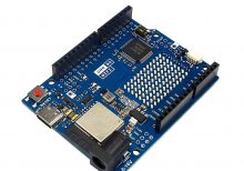
The Arduino Uno R4 WiFi is an advanced version of the popular Arduino Uno microcontroller board. It is based on the ATmega328P and includes integrated WiFi capabilities, making it ideal for IoT projects and wireless communication applications. The Uno R4 WiFi retains the ease of use and versatility of the original Uno, while adding wireless connectivity and enhanced performance.
Key Features:
- Microcontroller: ATmega328P
- Operating Voltage: 5V
- Input Voltage (recommended): 7-12V
- Input Voltage (limit): 6-20V
- Digital I/O Pins: 14 (of which 6 provide PWM output)
- Analog Input Pins: 6
- Flash Memory: 32 KB (ATmega328P) of which 0.5 KB used by bootloader
- SRAM: 2 KB (ATmega328P)
- EEPROM: 1 KB (ATmega328P)
- Clock Speed: 16 MHz
- WiFi: Integrated WiFi module for wireless connectivity
- USB Connection: For programming and power
Technical Specifications:
- Dimensions: 68.6 mm x 53.4 mm
- Weight: 25 g
- Communication: UART, SPI, I2C, WiFi
- On-board LEDs: TX, RX, Power, and Pin 13
- Power:
- DC Current per I/O Pin: 20 mA
- DC Current for 3.3V Pin: 50 mA
- Connectors:
- USB-B for programming and power
- Barrel jack for external power supply
- ICSP header for in-circuit programming
- 6-pin header for additional communication interfaces
- WiFi Specifications:
- Frequency: 2.4 GHz
- Protocols: IEEE 802.11 b/g/n
- Security: WEP, WPA, WPA2
Applications:
- Education: Ideal for teaching and learning electronics, programming, and IoT.
- Prototyping: Suitable for developing and testing new electronic projects with wireless connectivity.
- DIY Projects: Perfect for hobbyists creating custom gadgets, robots, and interactive installations with WiFi capabilities.
- IoT Projects: Can be used to build Internet of Things (IoT) applications by connecting sensors and actuators to the internet.
- Embedded Systems: Useful for designing and implementing embedded systems with wireless communication.
Datasheet:
For detailed technical information, refer to the Arduino Uno R4 WiFi Datasheet.
Manufacturer: Arduino
|
Description:
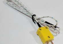
This thermocouple probe is designed for accurate temperature measurement in the range of -50°C to 400°C (-58°F to 752°F). It consists of a fine gauge wire made from two dissimilar metals (usually chromel and alumel for Type K thermocouples), which generate a voltage proportional to the temperature difference between the measurement junction and the reference junction. The probe is constructed with high-quality materials to ensure durability and reliability in various industrial, laboratory, and HVAC applications.
Key Features:
- Type: K thermocouple (common for general-purpose applications)
- Temperature Range: -50°C to 400°C (-58°F to 752°F)
- Probe Length: Standard lengths available, such as 1 meter (custom lengths may be available)
- Fast response time
- High accuracy and repeatability
- Suitable for harsh environments and high-temperature applications
- Flexible and easy to install
- Compatible with standard thermocouple connectors
Technical Specifications:
- Type: K thermocouple (other types available depending on application)
- Temperature Range: -50°C to 400°C (-58°F to 752°F)
- Accuracy: Typically ±1.5°C or ±0.4% (whichever is greater)
- Probe Diameter: Standard diameters available, typically 0.5 mm to 6 mm
- Response Time: Typically within a few seconds
- Sheath Material: Stainless steel, Inconel, or other suitable alloys
- Connection Type: Standard thermocouple connector, such as miniature thermocouple plugs or sockets
Applications:
- Industrial Temperature Monitoring
- HVAC (Heating, Ventilation, and Air Conditioning)
- Food Processing and Refrigeration
- Laboratory Testing and Calibration
- Process Control Systems
- Automotive and Aerospace
Datasheet:
For detailed technical information, refer to the datasheet
|
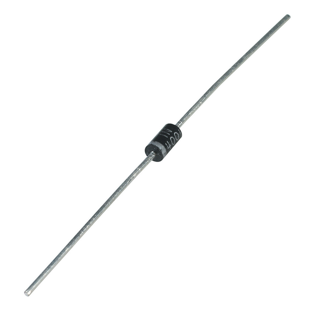
The 1N4001 is a general-purpose rectifier diode designed for a wide range of applications including power supplies, converters, and freewheeling diodes. This silicon diode is known for its reliability, low forward voltage drop, and high surge current capability. It is suitable for use in circuits requiring rectification, reverse polarity protection, and other general-purpose diode functions.
Key Features:
- Type: Silicon rectifier diode
- Forward Voltage Drop (Vf): Typically 1.1V at 1A
- Average Rectified Current (Io): 1A
- Peak Repetitive Reverse Voltage (Vrrm): 50V
- Surge Current (Ifsm): 30A
- Recovery Time: Standard recovery
- Package: DO-41
Technical Specifications:
- Maximum Repetitive Peak Reverse Voltage (Vrrm): 50V
- Maximum RMS Voltage (Vrms): 35V
- Maximum DC Blocking Voltage (Vdc): 50V
- Average Rectified Output Current (Io): 1A
- Non-Repetitive Peak Forward Surge Current (Ifsm): 30A
- Forward Voltage (Vf): 1.1V at 1A
- Reverse Current (Ir): 5µA at 50V
- Operating Temperature Range: -65°C to +150°C
Applications:
- Power supply rectification
- Freewheeling diode in motor applications
- Reverse polarity protection
- Converters and inverters
- General-purpose diode functions
Usage:
- Connect the anode (positive lead) to the positive side of the circuit.
- Connect the cathode (marked with a band) to the negative side of the circuit.
- Ensure the diode is correctly oriented to prevent reverse voltage damage.
- Integrate the diode into the circuit to achieve the desired rectification or protection function.
Caution:
- Verify the voltage and current ratings to ensure compatibility with your circuit.
- Avoid exceeding the maximum ratings to prevent damage to the diode.
- Ensure proper thermal management if operating near maximum current ratings.
Datasheet:
For detailed technical specifications, refer to the 1N4001 Diode Datasheet.
|
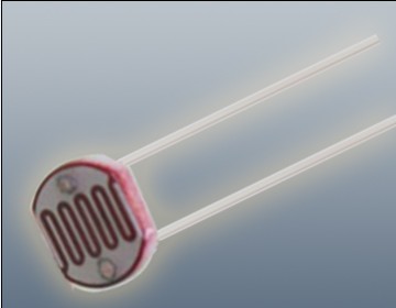
The Photoresistor LDR (Light Dependent Resistor) is a variable resistor whose resistance changes with the light intensity that falls upon it. It is widely used in light sensing applications and projects where detecting light levels is essential. LDRs are cost-effective, easy to use, and suitable for various electronic projects, including light meters, street lights, and other light-sensitive devices.
Key Features:
- Light Sensitivity: Resistance decreases with increasing light intensity
- Simple Interface: Easy to integrate with microcontrollers and analog circuits
- Low Cost: Economical solution for light detection
- Wide Range of Light Detection: Can detect various light levels from low to high intensity
- Compact Size: Fits easily into small projects
Technical Specifications:
- Resistance in Darkness: Typically 1MΩ (depending on specific model)
- Resistance in Bright Light: Typically 10-20kΩ (depending on specific model)
- Spectral Peak: Approximately 540nm (most sensitive to green light)
- Response Time: Rise time ~20ms, fall time ~30ms
- Operating Temperature Range: -30°C to +70°C
- Diameter: Typically 5mm to 10mm (depending on specific model)
Applications:
- Light Meters: Measure light intensity for photography and scientific applications.
- Street Lights: Automatic on/off control based on ambient light levels.
- Alarm Systems: Detect changes in light levels for security purposes.
- Consumer Electronics: Light-sensitive control in devices like clocks and displays.
- Educational Projects: Common component in learning modules for electronics.
Usage:
- Circuit Integration: Connect the LDR in a voltage divider circuit with a fixed resistor to create a variable voltage output based on light intensity.
- Microcontroller Interface: Read the voltage output from the LDR circuit using an analog input pin on a microcontroller.
- Programming: Write code to interpret the analog signal and perform actions based on light levels (e.g., turning on an LED when it gets dark).
- Testing: Calibrate the LDR circuit for the desired light sensitivity by adjusting the fixed resistor value.
Caution:
- Environment: Avoid exposure to extreme temperatures and humidity, which may affect the LDR’s performance.
- Handling: Handle with care to avoid damaging the sensitive surface of the LDR.
Datasheet:
For detailed technical specifications, refer to the Photoresistor LDR Datasheet.
|
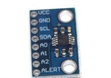
Description: The MCU-9808 MCP9808 High Precision I2C Temperature Sensor Module is a high-accuracy temperature sensor designed for precise temperature measurements in a variety of applications. Utilizing the MCP9808 sensor IC, this module offers high-resolution temperature readings via the I2C interface, making it suitable for integration into temperature monitoring systems and other temperature-sensitive applications.
Key Features:
- High precision temperature measurement with ±0.5°C accuracy
- I2C communication interface for easy integration with microcontrollers
- Wide temperature range: -40°C to +125°C
- Low power consumption for battery-operated systems
- Compact design for space-constrained applications
Technical Specifications:
- Sensor Type: MCP9808
- Temperature Range: -40°C to +125°C
- Accuracy: ±0.5°C (typical)
- Resolution: 0.0625°C
- Communication Interface: I2C
- Supply Voltage: 2.7V to 5.5V DC
- Operating Temperature Range: -40°C to +125°C
- Dimensions: 20 mm x 20 mm
Applications:
- Temperature monitoring systems
- Environmental sensors
- Battery and power management systems
- Industrial and laboratory equipment
- HVAC systems
Datasheet: For detailed technical information, refer to the MCP9808 Datasheet.
|
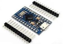
The Arduino Pro Micro is a compact and versatile microcontroller board based on the ATmega32U4 microchip. It is part of the Arduino family and designed for projects where space is limited. The Pro Micro board features built-in USB capabilities, allowing it to emulate a keyboard, mouse, or other USB devices, making it suitable for a wide range of applications including custom input devices and embedded systems.
Key Features:
- Microcontroller: ATmega32U4
- Operating Voltage: 5V
- Input Voltage (recommended): 7-12V
- Digital I/O Pins: 18
- Analog Input Pins: 9
- Flash Memory: 32 KB (ATmega32U4), of which 4 KB used by bootloader
- SRAM: 2.5 KB
- EEPROM: 1 KB
- Clock Speed: 16 MHz
- USB: Built-in USB functionality for direct connection to computers and emulation of USB devices
Technical Specifications:
- Dimensions: 33 mm x 18 mm
- Weight: Approximately 8 g
- Communication: UART, SPI, I2C, USB
- On-board LEDs: TX, RX, Power, and one user-defined LED
- Power:
- DC Current per I/O Pin: 40 mA
- DC Current for 3.3V Pin: 50 mA
- Connectors:
- USB Micro-B for programming and power
- 6-pin header for serial communication
- Pins for additional communication interfaces and power
Applications:
- Custom Input Devices: Can be used to create custom keyboards, mice, and other input devices.
- Embedded Systems: Suitable for small-scale embedded projects where USB connectivity is required.
- Prototyping: Ideal for rapid prototyping and development due to its compact size and USB capability.
- IoT Projects: Can be integrated into Internet of Things (IoT) devices for various control and monitoring applications.
- Wearables: Perfect for wearable electronics and projects requiring a small form factor.
Datasheet:
For detailed technical information, refer to the Arduino Pro Micro Datasheet.
|
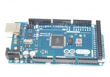
The Arduino Mega 2560 is a popular microcontroller board based on the ATmega2560 chip, offering a substantial increase in input/output (I/O) pins, memory, and functionality compared to other Arduino boards. It is designed for projects requiring a large number of I/O pins or more complex operations, making it suitable for advanced hobbyist and professional applications.
Key Features:
- ATmega2560 Microcontroller
- 256KB Flash memory for storing code
- 8KB SRAM for data storage
- 4KB EEPROM for non-volatile data storage
- 54 Digital I/O pins (15 with PWM output)
- 16 Analog input pins
- 4 Hardware serial ports (UARTs)
- 16 MHz Clock speed
- USB connection for programming and power
- Power jack for external power supply
- Built-in LED on pin 13
Technical Specifications:
- Microcontroller: ATmega2560
- Operating Voltage: 5V
- Input Voltage (recommended): 7-12V
- Input Voltage (limit): 6-20V
- Digital I/O Pins: 54 (15 with PWM)
- Analog Input Pins: 16
- Flash Memory: 256 KB (of which 8 KB used by bootloader)
- SRAM: 8 KB
- EEPROM: 4 KB
- Clock Speed: 16 MHz
- Dimensions: 101.6 mm x 53.3 mm (4 in x 2.1 in)
- Weight: Approximately 37 g (1.3 oz)
Applications:
- Robotics: Control motors, sensors, and other peripherals for robotic systems
- Home Automation: Interface with various sensors and actuators for smart home projects
- Data Logging: Collect and store data from multiple sensors for analysis
- Prototyping: Develop and test complex electronic circuits and systems
- Educational Projects: Use in educational environments to teach microcontroller programming and electronics
Usage:
- Connect the Arduino Mega 2560 to your computer via USB for programming.
- Use the Arduino IDE to write and upload code to the board.
- Interface with external hardware using the I/O pins for various applications.
- Power the board using either the USB connection or an external power supply.
Caution:
- Ensure the input voltage does not exceed the recommended range to avoid damaging the board.
- Verify connections to avoid incorrect wiring or short circuits.
- Handle with care to prevent damage to the board or its components.
Datasheet:
For detailed technical specifications, refer to the Arduino Mega 2560 Datasheet.
|
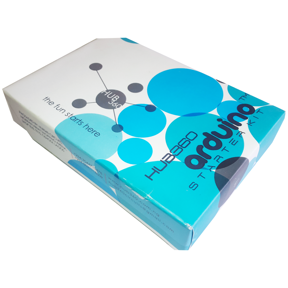
The Hub360 Arduino Starter Kit is a comprehensive package designed for beginners and enthusiasts looking to dive into the world of electronics and programming. This kit includes Arduino Uno, which is a microcontroller board based on the ATmega328P. The kit provides a variety of components and modules to help users learn and experiment with different electronic projects and concepts.
Key Features:
- Includes Arduino Uno board
- Comprehensive set of components and modules for various projects
- Ideal for beginners and hobbyists
- Detailed tutorial and project guide included
- USB interface for easy programming and power
- Compatible with Arduino IDE and various libraries
Technical Specifications:
- Microcontroller: ATmega328P
- Operating Voltage: 5V
- Input Voltage (recommended): 7-12V
- Digital I/O Pins: 14 (6 PWM outputs)
- Analog Input Pins: 6
- DC Current per I/O Pin: 20mA
- Flash Memory: 32KB (ATmega328P) of which 0.5KB used by bootloader
- SRAM: 2KB (ATmega328P)
- EEPROM: 1KB (ATmega328P)
- Clock Speed: 16 MHz
Kit Contents:
- ARDUINO BOARD 1
- ARDUINO USB CABLE 1
- ARDUINO BATTERY CONNECTOR 1
- 400 HOLE BREADBOARD 1
- LED (RED, YELLOW , GREEN, WHITE) 20
- RGB LED 1
- JUMPER WIRE(M-M, M-F, F-F) 120
- PHOTORESISTOR (LDR) 3
- MALE HEADERS 40
- ULTRASONIC SENSOR 1
- FLAME SENSOR 1
- TEMP./HUMIDITY SENSOR 1
- TILT SENSOR 1
- LASER SENSOR 1
- PIR MOTION SENSOR 1
- RESISTORS(220K, 1K, 10K,100K) 40
- 7 SEGMENT DISPLAY 1
- SG90 SERVO 1
- REMOTE CONTROL 1
- BUZZER 1
- 2N2222 2
- TSOP 1838 1
- RF TRANSMITTER 1
- RF RECEIVER 1
- TACT SWITCH 5
- 16*2 LCD DISPLAY
Applications:
- Learning basic electronics and programming
- Building interactive projects and prototypes
- Developing skills in microcontroller-based design
- Experimenting with sensors and actuators
- Creating DIY electronic devices
Usage:
- Setup:
- Connect the Arduino Uno board to your computer using the USB cable.
- Install the Arduino IDE and configure it to recognize the board.
- Programming:
- Write or upload sample code (sketches) to the Arduino board using the Arduino IDE.
- Utilize the provided components and modules to build and test different circuits.
- Experimentation:
- Follow the detailed tutorials and project guide to create various projects.
- Modify and expand on the sample projects to enhance learning and creativity.
Caution:
- Handle the components carefully to avoid damage.
- Ensure proper connections and polarity to prevent short circuits or component failure.
- Verify the code and circuit connections before powering the board.
Datasheet:
For detailed technical specifications of the Arduino Uno, refer to the Arduino Uno Datasheet.
|
