|
Description |
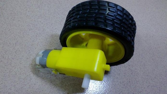
The Smart Car Wheel with Geared Motor is a high-quality component designed for building or upgrading smart car robotic projects. This wheel and motor combination offers reliable performance with excellent traction and torque, making it ideal for a variety of robotic applications. Whether you are a hobbyist, student, or professional, this component simplifies the construction of a robust and efficient robotic platform.
Key Features:
- Integrated Set: Includes one wheel and one geared motor.
- High Traction Wheel: Designed to provide optimal grip on various surfaces.
- Geared Motor: Delivers high torque and stable performance.
- Standard Compatibility: Fits most smart car and robotic chassis kits.
- Easy Installation: Simple to mount and connect to motor drivers.
- Durable Build: Made from high-quality materials for longevity and reliability.
Technical Specifications:
- Wheel Diameter: Typically 65mm to 70mm
- Wheel Width: Approximately 25mm
- Motor Voltage: 3V to 6V DC
- Motor Speed: Approximately 200 RPM at 6V
- Torque: Suitable for moderate loads in small to medium-sized robots
- Gear Ratio: Typically 1:48 (varies by model)
- Shaft Diameter: Standard 6mm D-shaft for secure attachment
Applications:
- Robotic Vehicles: Perfect for building smart cars and autonomous robots.
- DIY Projects: Enhance or create custom robotic projects.
- Educational Kits: Ideal for teaching robotics and electronics.
- Prototyping: Useful for developing and testing new robotic designs.
- Hobbyist Projects: Suitable for various robotics hobbies and competitions.
Usage:
- Mounting: Attach the wheel to the geared motor using the provided screws and nuts.
- Wiring: Connect the motor to your motor driver and control board (e.g., Arduino, Raspberry Pi).
- Power Supply: Ensure the motor receives the appropriate voltage and current for optimal performance.
- Programming: Write code to control the motor for desired movements and behaviors.
- Testing: Test the assembled wheel and motor on your smart car chassis to ensure smooth operation.
Caution:
- Proper Voltage: Use the recommended voltage to avoid damaging the motor.
- Secure Mounting: Ensure all components are securely attached to prevent disassembly during use.
- Safe Operation: Test in a safe environment to avoid damage to the robot and surroundings.
|
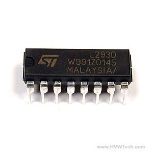
The L293 is a quadruple high-current half-H driver designed to provide bidirectional drive currents of up to 1A at voltages from 4.5V to 36V. It is ideal for driving inductive loads such as relays, solenoids, DC and stepping motors. The L293 IC is commonly used in robotics and embedded systems for motor control applications.
Key Features:
- Capable of driving two DC motors or one stepper motor
- Provides bidirectional drive currents up to 1A per channel
- Wide supply voltage range from 4.5V to 36V
- Separate input-logic supply
- Thermal shutdown protection
- High noise immunity
- Internal ESD protection
- Compatible with TTL and CMOS logic levels
Technical Specifications:
- Supply Voltage (VCC1 – Logic): 4.5V to 7V
- Supply Voltage (VCC2 – Motor): 4.5V to 36V
- Output Current: 1A per channel (continuous)
- Peak Output Current: 2A per channel (non-repetitive, t < 5ms)
- Input Voltage High: 2.3V (min)
- Input Voltage Low: 1.5V (max)
- Enable Voltage High: 2.3V (min)
- Enable Voltage Low: 1.5V (max)
- Power Dissipation: 5W (typical)
- Operating Temperature Range: 0°C to +70°C
- Package Type: 16-pin DIP (Dual In-line Package), SOIC (Small Outline Integrated Circuit), or TSSOP (Thin Shrink Small Outline Package)
Applications:
- Robotics
- Motor control for DC motors and stepper motors
- Relay drivers
- Solenoid drivers
- High current LED drivers
- Automotive applications
Usage:
- Connection:
- Connect VCC1 to the logic voltage (4.5V to 7V).
- Connect VCC2 to the motor voltage (4.5V to 36V).
- Connect the input pins (IN1, IN2, IN3, IN4) to the microcontroller or control logic.
- Connect the output pins (OUT1, OUT2, OUT3, OUT4) to the motor terminals.
- Enable the channels by connecting the enable pins (EN1, EN2) to the logic high or via PWM signals for speed control.
- Control:
- Use the input pins to set the direction of the motor rotation.
- Use PWM on the enable pins to control the speed of the motors.
- Protection:
- Ensure proper heat sinking or cooling as the IC can get hot under high loads.
- Use external diodes if necessary to protect against back EMF generated by motors.
Caution:
- Ensure the total current does not exceed the maximum ratings of the IC.
- Provide adequate cooling to prevent thermal shutdown.
- Avoid short circuits and excessive voltage spikes.
Datasheet:
For detailed technical specifications, refer to the L293 Motor Driver IC Datasheet.
|

