|
Description |
The Raspberry Pi HDMI to VGA Converter is a compact adapter designed to enable the connection of a Raspberry Pi to a VGA display or monitor. This converter transforms the digital HDMI output from the Raspberry Pi into an analog VGA signal, allowing for compatibility with older monitors and projectors that support VGA input. It is an essential accessory for users who need to interface their Raspberry Pi with VGA-equipped display devices.
Key Features:
- HDMI to VGA Conversion: Converts HDMI digital signal to VGA analog signal
- Resolution Support: Supports common VGA resolutions up to 1080p
- Power Supply: Powered through the HDMI connection (no additional power required)
- Compact Design: Small and lightweight for easy integration
- Plug-and-Play: No additional drivers or software required
- Audio Support: Some models may include a separate audio output for connecting external speakers
Technical Specifications:
- Input: HDMI Type A (female)
- Output: VGA (15-pin D-Sub, female)
- Resolution Support: Up to 1920×1080 (1080p)
- Power Supply: Powered through HDMI connection (requires sufficient HDMI power)
- Dimensions: Typically compact, around 50mm x 30mm x 20mm
- Weight: Approximately 50g
Applications:
- Connecting Raspberry Pi to VGA monitors or projectors
- Using older VGA display equipment with modern HDMI devices
- Educational and DIY projects requiring VGA display output
- Retro computing and display setups
Usage:
- Connect the HDMI end of the converter to the HDMI output of the Raspberry Pi.
- Connect the VGA end of the converter to the VGA input of the monitor or projector.
- Optionally, connect an external audio cable if the converter provides a separate audio output.
- Power on the Raspberry Pi and the display device to start using the setup.
Caution:
- Ensure the HDMI and VGA connections are secure to prevent signal loss or display issues.
- Verify that the VGA display supports the resolution output by the Raspberry Pi.
- Check the power requirements of the HDMI connection to ensure proper operation.
Datasheet:
For detailed technical specifications, refer to the Raspberry Pi HDMI to VGA Converter Datasheet.
|
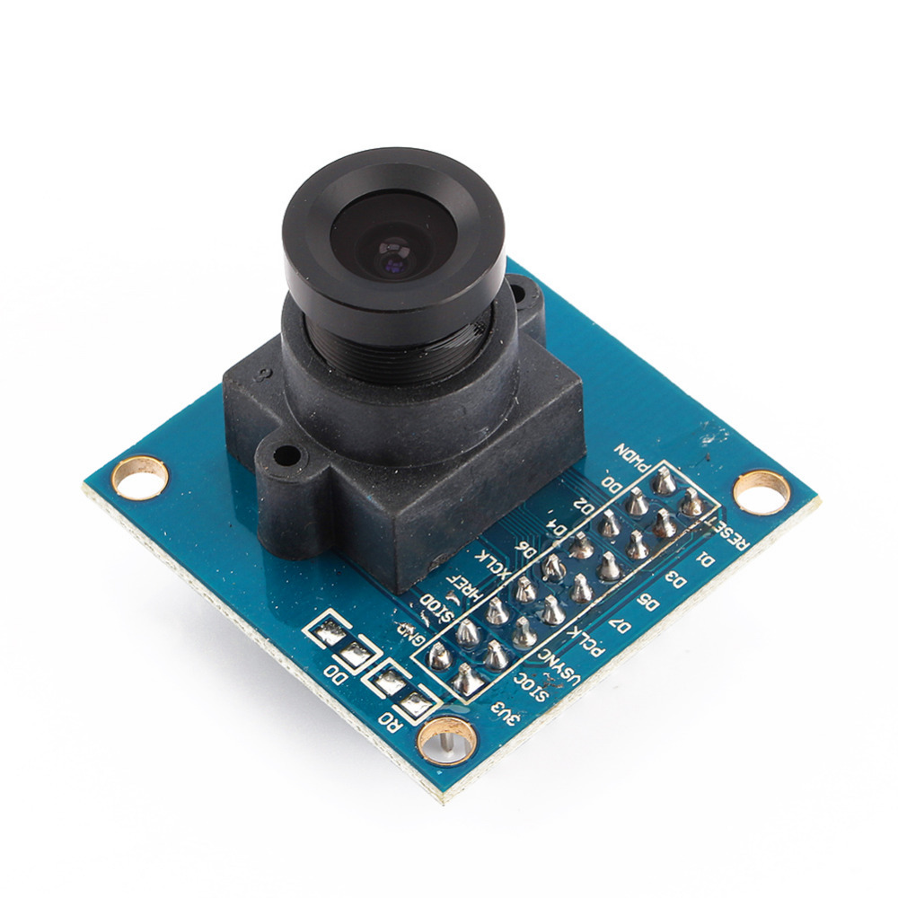
The OV7670 Camera Module is a low-cost camera module designed for use with Arduino and other microcontroller platforms. It features the OV7670 image sensor, which provides basic image capture capabilities suitable for low-resolution and hobbyist applications. This module is ideal for educational projects, DIY electronics, and simple image processing tasks.
Key Features:
- VGA (640×480) resolution capability
- Low power consumption
- Small form factor, easy to integrate with Arduino
- Includes an integrated image sensor (OV7670)
- Supports various output formats, including RGB565 and YUV422
- Built-in FIFO buffer to store image data temporarily
Technical Specifications:
- Image Sensor: OV7670 CMOS
- Resolution: VGA (640×480 pixels)
- Output Formats: RGB565, YUV422
- Power Supply: 3.3V DC (requires voltage regulator for Arduino 5V supply)
- Interface: 8-bit parallel data bus
- Operating Temperature Range: -20°C to +70°C
- Frame Rate: Up to 30 frames per second (fps) at VGA resolution
- Lens Type: Fixed-focus lens
Applications:
- Basic image capture and processing
- Educational and experimental projects involving image processing
- Low-resolution video streaming
- Simple security or surveillance systems
- Integration with Arduino for image-related applications
Usage:
- Connection: Connect the OV7670 module to the Arduino using the provided pin headers. Typically, connections include power (3.3V), ground, and data lines.
- Configuration: Use Arduino libraries and example code to configure the camera module and capture images. The module usually requires initialization and setup via I2C or SPI.
- Processing: Retrieve image data from the module and process it using Arduino or other compatible microcontrollers.
- Integration: Integrate the camera module into your project to enable image capturing or video streaming functionality.
Caution:
- The OV7670 operates at 3.3V, so be careful not to apply 5V directly to the module to avoid damage.
- Properly handle and secure the module to avoid damage to the delicate components.
- Ensure correct wiring and connections according to the module’s datasheet to avoid communication issues.
Datasheet:
For detailed technical specifications, refer to the OV7670 Camera Module Datasheet.
|
The AS608 Optical Fingerprint Module is a compact and efficient fingerprint recognition device designed for integration into security systems. It uses optical fingerprint sensing technology to capture and store fingerprint data, providing high accuracy and reliability in biometric authentication. The module is suitable for various applications, including access control, time attendance systems, and personal identification.
Key Features:
- High-precision optical fingerprint sensor
- Fast and accurate fingerprint recognition
- Supports fingerprint storage and matching
- Easy to integrate with microcontrollers and development boards
- Low power consumption
- Built-in algorithm for fingerprint processing
- UART interface for communication
Technical Specifications:
- Supply Voltage: 3.6V to 6V DC
- Operating Current: <120mA
- Fingerprint Capacity: 162 templates
- Verification Time: <1 second
- False Acceptance Rate (FAR): <0.001%
- False Rejection Rate (FRR): <0.1%
- Interface: UART (TTL logic level)
- Communication Speed: 9600 baud (default, adjustable)
- Working Temperature: -20°C to 50°C
- Dimensions: 32mm x 32mm x 10mm
- Weight: 20g
Applications:
- Access control systems
- Time attendance systems
- Personal identification devices
- Biometric authentication systems
- Safe and locker systems
- IoT security applications
Usage:
- Connect the module to a microcontroller or development board using the UART interface.
- Supply the appropriate voltage to power the module.
- Use the provided library or code examples to enroll and verify fingerprints.
- Integrate the fingerprint matching results into your security system.
Caution:
- Avoid exposing the sensor to direct sunlight or intense light.
- Keep the sensor clean for optimal performance.
- Handle the module with care to prevent damage to the optical sensor.
Datasheet:
For detailed technical specifications, refer to the AS608 Optical Fingerprint Module Datasheet.
|
The Raspberry Pi HDMI Cable 1.5m is a high-quality cable designed to connect your Raspberry Pi to HDMI-enabled displays, such as monitors and TVs. This cable ensures a reliable and clear transmission of audio and video signals, supporting high-definition resolutions for an enhanced viewing experience. With a length of 1.5 meters, it provides ample reach for convenient setup and connectivity in various environments.
Key Features:
- High-Quality Transmission: Ensures clear and reliable audio and video signal transfer
- HD Compatibility: Supports resolutions up to 1080p and beyond, depending on the connected devices
- Durable Construction: Made with high-quality materials to ensure longevity and resistance to wear
- Length: 1.5 meters for flexible and convenient setup
- Universal Compatibility: Works with all HDMI-enabled devices, including Raspberry Pi, monitors, TVs, and projectors
Technical Specifications:
- Cable Length: 1.5 meters
- Connector Type: HDMI Type A (male to male)
- Resolution Support: Up to 1080p, 4K (depends on device capabilities)
- Bandwidth: High-speed HDMI
- Material: Durable PVC jacket with shielded cable for interference reduction
- Color: Typically black
- Compatibility: Raspberry Pi models and other HDMI-enabled devices
Applications:
- Connecting Raspberry Pi to HDMI monitors or TVs
- High-definition multimedia interface for home entertainment systems
- Use in classrooms and educational setups for displaying content from Raspberry Pi
- Presentations and demonstrations with projectors
- Any application requiring HDMI connectivity between devices
Usage:
- Connect one end of the HDMI cable to the HDMI port on your Raspberry Pi.
- Connect the other end to the HDMI port on your display device (monitor, TV, or projector).
- Power on both the Raspberry Pi and the display device.
- Select the correct HDMI input on your display device to view the Raspberry Pi output.
Caution:
- Handle the cable with care to avoid bending or damaging the connectors.
- Ensure both devices are powered off when connecting or disconnecting the HDMI cable to prevent damage.
- Avoid placing heavy objects on the cable to maintain its integrity.
Datasheet:
For detailed technical specifications, refer to the Raspberry Pi HDMI Cable 1.5m Datasheet.
|


