|
Description |
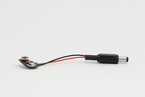
The Arduino 9V Battery Connector is a convenient accessory for powering Arduino boards and other compatible devices. It allows you to connect a standard 9V battery to the Arduino’s power jack, providing a portable power solution for your projects. This connector is essential for mobile and battery-operated applications, offering an easy and reliable way to supply power to your electronics.
Key Features:
- Compatible with standard 9V batteries
- Easy to connect and use
- Provides a secure and stable power connection
- Compact and portable design
- Durable construction for long-lasting use
- Standard DC barrel plug compatible with Arduino boards
Technical Specifications:
- Connector Type: DC barrel plug (center-positive)
- Barrel Plug Dimensions: Outer diameter 5.5mm, inner diameter 2.1mm
- Battery Connector Type: Snap-on connector for 9V battery
- Cable Length: Approximately 15 cm
- Material: Plastic and metal connectors with insulated wire
- Color: Typically black with red and black wires
Applications:
- Portable Arduino projects
- Battery-operated electronics
- Prototyping and testing
- Educational kits
- DIY electronics
Usage:
- Connection:
- Snap the 9V battery connector onto the terminals of a standard 9V battery.
- Insert the DC barrel plug into the power jack of your Arduino board or compatible device.
- Powering:
- Ensure the polarity of the connections is correct (center-positive) to avoid damage to the board.
- The Arduino will draw power from the 9V battery through the connector.
- Monitoring:
- Monitor the battery voltage periodically to ensure it remains within the acceptable range for your Arduino board (typically 7-12V).
Caution:
- Ensure the connector is securely attached to the battery terminals to prevent intermittent connections.
- Avoid short-circuiting the battery terminals.
- Do not expose the connector to moisture or extreme temperatures.
- Remove the battery from the connector when not in use to prevent battery drain.
Datasheet:
Refer to the manufacturer’s guidelines or specifications for further details.
|
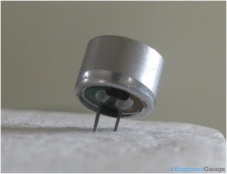
The Condenser Mic 4.5×2.2mm is a small-sized, high-sensitivity electret microphone. It is designed for a wide range of audio applications, including voice recording, telecommunication devices, and various consumer electronics. Its compact size and high sensitivity make it ideal for embedding in small devices.
Key Features:
- High sensitivity and low noise
- Small and compact size
- Wide frequency response
- Low power consumption
- Omnidirectional pickup pattern
- Easy to integrate into electronic circuits
Technical Specifications:
- Type: Electret condenser microphone
- Dimensions: 4.5mm (diameter) x 2.2mm (height)
- Sensitivity: -42dB ±3dB (0dB = 1V/Pa at 1kHz)
- Frequency Response: 20Hz to 16kHz
- Impedance: ≤ 2.2kΩ
- Operating Voltage: 1.5V to 10V DC
- Current Consumption: ≤ 0.5mA
- Signal-to-Noise Ratio: ≥ 60dB
- Directivity: Omnidirectional
- Operating Temperature Range: -20°C to +70°C
Applications:
- Voice recording devices
- Telecommunication equipment
- Hearing aids
- Portable audio recorders
- Consumer electronics
- Smart home devices
- Speech recognition systems
Usage:
- Connection:
- Connect the microphone’s output pin to the input of an amplifier or preamp circuit.
- Connect the power supply (1.5V to 10V DC) to the microphone.
- Ensure the ground connection is properly made to avoid noise interference.
- Integration:
- Place the microphone in a suitable location to capture sound effectively.
- Embed the microphone in devices ensuring the sound entry is not obstructed.
- Circuit Design:
- Use appropriate capacitors and resistors as per the microphone’s requirements.
- Design the circuit to provide a stable power supply and proper impedance matching.
Caution:
- Handle the microphone with care to avoid physical damage.
- Protect the microphone from exposure to moisture and extreme temperatures.
- Avoid applying excessive voltage to prevent damage to the microphone.
Datasheet:
For detailed technical specifications, refer to the Condenser Microphone Datasheet.
|
The T Plug Pair, also known as Deans connectors, is a set of high-current connectors commonly used in RC models, batteries, and other electronic applications requiring reliable and secure power connections. These connectors are known for their low resistance, high current carrying capacity, and easy-to-use design.
Key Features:
- Type: T Plug (Deans connectors)
- Current Capacity: High current capacity for demanding applications
- Design: Compact design for ease of use and installation
- Material: High-quality plastic housing with gold-plated metal contacts for improved conductivity and durability
- Polarity: Clearly marked to prevent incorrect connections
- Compatibility: Widely compatible with RC batteries, ESCs, and other electronic devices
Technical Specifications:
- Dimensions:
- Length: Approximately 15 mm
- Width: Approximately 8 mm
- Height: Approximately 20 mm
- Weight: Approximately 2-3 g per connector
- Material:
- Contacts: Gold-plated for low resistance and high conductivity
- Housing: Heat-resistant plastic
- Current Rating: Up to 60A continuous (varies by manufacturer)
- Voltage Rating: Typically up to 20V
- Connection Type: Soldered connections for secure attachment to wires
Applications:
- RC Models: Commonly used in RC cars, boats, airplanes, and drones for connecting batteries to ESCs and motors.
- Batteries: Ideal for making secure connections between batteries and electronic devices.
- DIY Electronics: Useful for hobbyists and engineers working on custom electronic projects requiring reliable power connections.
- Power Systems: Suitable for high-current applications in various power systems and electronic setups.
Datasheet:
For detailed technical information, refer to the T Plug Pair Datasheet.
|
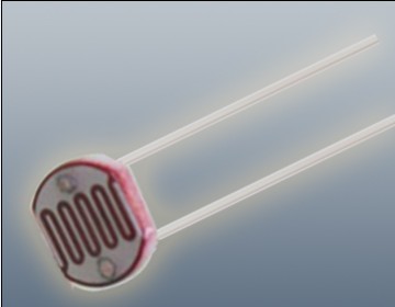
The Photoresistor LDR (Light Dependent Resistor) is a variable resistor whose resistance changes with the light intensity that falls upon it. It is widely used in light sensing applications and projects where detecting light levels is essential. LDRs are cost-effective, easy to use, and suitable for various electronic projects, including light meters, street lights, and other light-sensitive devices.
Key Features:
- Light Sensitivity: Resistance decreases with increasing light intensity
- Simple Interface: Easy to integrate with microcontrollers and analog circuits
- Low Cost: Economical solution for light detection
- Wide Range of Light Detection: Can detect various light levels from low to high intensity
- Compact Size: Fits easily into small projects
Technical Specifications:
- Resistance in Darkness: Typically 1MΩ (depending on specific model)
- Resistance in Bright Light: Typically 10-20kΩ (depending on specific model)
- Spectral Peak: Approximately 540nm (most sensitive to green light)
- Response Time: Rise time ~20ms, fall time ~30ms
- Operating Temperature Range: -30°C to +70°C
- Diameter: Typically 5mm to 10mm (depending on specific model)
Applications:
- Light Meters: Measure light intensity for photography and scientific applications.
- Street Lights: Automatic on/off control based on ambient light levels.
- Alarm Systems: Detect changes in light levels for security purposes.
- Consumer Electronics: Light-sensitive control in devices like clocks and displays.
- Educational Projects: Common component in learning modules for electronics.
Usage:
- Circuit Integration: Connect the LDR in a voltage divider circuit with a fixed resistor to create a variable voltage output based on light intensity.
- Microcontroller Interface: Read the voltage output from the LDR circuit using an analog input pin on a microcontroller.
- Programming: Write code to interpret the analog signal and perform actions based on light levels (e.g., turning on an LED when it gets dark).
- Testing: Calibrate the LDR circuit for the desired light sensitivity by adjusting the fixed resistor value.
Caution:
- Environment: Avoid exposure to extreme temperatures and humidity, which may affect the LDR’s performance.
- Handling: Handle with care to avoid damaging the sensitive surface of the LDR.
Datasheet:
For detailed technical specifications, refer to the Photoresistor LDR Datasheet.
|
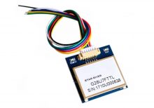
The VK2828 G28U7FTTL is a high-performance GPS module designed for aviation and other high-precision applications. It features a wide range of operational frequencies and is capable of delivering accurate positional data for navigation and tracking purposes. The module is ideal for integration into systems requiring reliable and precise GPS information.
Key Features:
- High Update Rate: Capable of updating position data from 1Hz to 10Hz, allowing for smooth and accurate tracking
- Sensitivity: Designed for use in aviation, providing robust performance in various environmental conditions
- Compatibility: Supports standard GPS protocols for easy integration into existing systems
- Compact Size: Suitable for integration into space-constrained applications
Technical Specifications:
- Type: GPS Module
- Model: VK2828 G28U7FTTL
- Update Rate: 1Hz to 10Hz
- Frequency Range: Supports standard GPS frequencies
- Sensitivity: High sensitivity for accurate positioning
- Protocol: NMEA-0183
- Operating Voltage: Typically 3.3V to 5V DC
- Power Consumption: Low power consumption for battery-operated applications
- Dimensions: Varies by model, generally compact for easy integration
- Antenna: May include an external or integrated antenna depending on the model
Applications:
- Aviation: Navigation and tracking for aircraft
- Marine: Boat and ship navigation
- Automotive: Advanced driver-assistance systems (ADAS)
- Outdoor Activities: Hiking and sports tracking
- Industrial: Asset tracking and fleet management
Usage:
- Powering the Module: Connect the GPS module to a suitable power source within the specified voltage range.
- Connecting the Antenna: Ensure the antenna is properly connected and positioned for optimal signal reception.
- Data Integration: Use the NMEA protocol to receive GPS data, including latitude, longitude, altitude, and time.
- Integration: Connect the GPS module to your system or application for real-time tracking and navigation.
Caution:
- Signal Reception: Ensure the module has a clear view of the sky for optimal GPS signal reception.
- Voltage: Verify the operating voltage to avoid damage to the module.
- Antenna Placement: Position the antenna to minimize interference and maximize signal strength.
Datasheet:
For detailed technical specifications, refer to the VK2828 G28U7FTTL Datasheet .
|
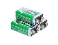
The 9V battery is a compact, rectangular-shaped battery commonly used in various electronic devices and household applications. Known for its reliability and long shelf life, the 9V battery provides a steady voltage output, making it ideal for devices that require a stable power source. It is widely used in smoke detectors, multimeters, transistor radios, and other portable electronic devices.
Key Features:
- Type: 9V battery
- Voltage: 9 volts
- Capacity: Varies by manufacturer (typically between 500mAh to 1200mAh)
- Shelf Life: Up to 5 years
- Size: Standard 9V (rectangular with snap connectors)
- Reliable Performance: Consistent and stable power output
- Leak-resistant: Designed to prevent leakage and protect devices
Technical Specifications:
- Voltage: 9V
- Capacity: Typically between 500mAh to 1200mAh
- Dimensions: 48.5mm x 26.5mm x 17.5mm
- Weight: Approximately 45g
- Terminal Type: Snap connector
- Chemistry: Available in Alkaline, Lithium, or Rechargeable NiMH
- Operating Temperature Range: -20°C to +54°C
Applications:
- Smoke Detectors: Reliable power source for safety devices.
- Multimeters: Provides consistent voltage for accurate measurements.
- Transistor Radios: Powers portable radios for extended periods.
- Portable Electronic Devices: Suitable for various battery-operated devices.
- Toys: Used in electronic toys and gadgets.
Usage:
- Installation: Insert the 9V battery into the device, ensuring correct polarity alignment.
- Replacement: Replace the battery when the device indicates low power or performance drops.
- Storage: Store batteries in a cool, dry place to maximize shelf life.
Caution:
- Proper Disposal: Follow local regulations for battery disposal.
- Avoid Short-circuiting: Do not connect terminals directly, as it may cause overheating or leakage.
- Do Not Recharge: Non-rechargeable 9V batteries should not be recharged.
Datasheet:
For detailed technical specifications, refer to the 9V Battery Datasheet.
|
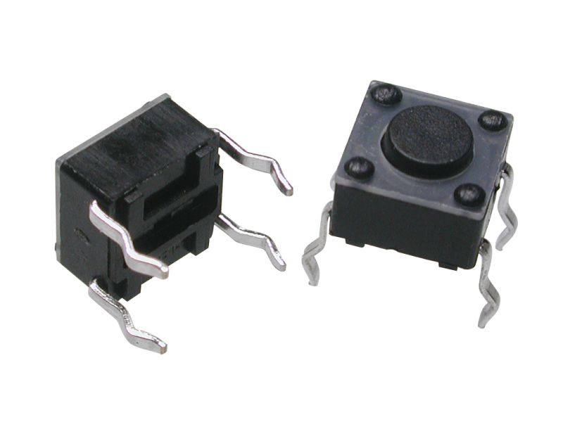
A Tact Switch, also known as a tactile switch, is a type of switch designed to provide a tactile feedback when pressed. These switches are commonly used in electronic devices for user input, such as in keyboards, remote controls, and various consumer electronics. Tact switches are known for their compact size, reliability, and ease of integration into circuits.
Key Features:
- Tactile Feedback: Provides a satisfying click feel when pressed.
- Compact Size: Small and suitable for space-constrained applications.
- Reliability: Durable and designed for a high number of actuation cycles.
- Variety of Sizes: Available in different sizes and heights to fit various designs.
- Easy Mounting: Can be mounted on PCBs with through-hole or surface-mount technology.
- Wide Application Range: Suitable for a variety of electronic devices and applications.
Technical Specifications:
- Contact Rating: Typically 50mA, 12V DC
- Contact Resistance: ≤ 100mΩ
- Insulation Resistance: ≥ 100MΩ at 100V DC
- Dielectric Strength: 250V AC for 1 minute
- Operating Force: Typically 160gf (varies by model)
- Travel: Typically 0.25mm to 0.5mm
- Operating Life: Typically 100,000 to 1,000,000 cycles
- Operating Temperature Range: -20°C to +70°C
Applications:
- Consumer Electronics: Used in remote controls, calculators, and gaming controllers.
- Computer Peripherals: Keyboards, mice, and other input devices.
- Home Appliances: Control panels for microwaves, washing machines, and other appliances.
- Automotive: Control buttons on car dashboards and steering wheels.
- Industrial Equipment: Control panels and user interfaces for machinery.
- DIY Projects: Suitable for custom electronic projects and prototypes.
Usage:
- Mounting: Solder the tact switch onto a PCB, ensuring correct alignment of the pins.
- Wiring: Connect the switch to your circuit, typically using pull-up or pull-down resistors.
- Testing: Verify the switch functionality by pressing it and checking the response in your circuit.
- Integration: Integrate the switch into your final product, ensuring it is accessible and functions as intended.
Caution:
- Debouncing: Implement debouncing in your software to ensure accurate readings.
- Proper Soldering: Avoid excessive heat during soldering to prevent damage to the switch.
- Environmental Conditions: Ensure the switch is used within its specified temperature and humidity range.
Datasheet:
For detailed technical specifications, refer to the Tact Switch Datasheet.
|
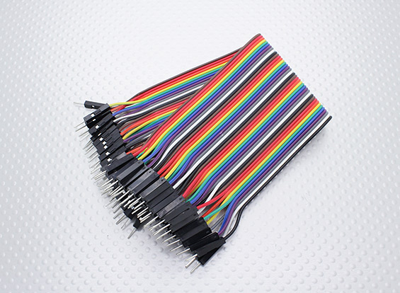
The Male-Male Jumper Wires (Set) is an essential component for breadboarding and prototyping in electronics projects. These wires are used to establish quick and reliable connections between various points in a circuit, such as between the pins of a microcontroller, sensors, modules, and other components. The set typically includes a variety of lengths and colors to help with organizing and identifying connections.
Key Features:
- Easy and quick connections for breadboards and other prototyping environments
- Variety of lengths and colors for flexibility and organization
- Durable and reusable
- Compatible with standard 0.1” (2.54mm) pitch headers
- Ideal for Arduino, Raspberry Pi, and other microcontroller projects
Technical Specifications:
- Connector Type: Male to Male
- Pin Spacing: 0.1” (2.54mm)
- Wire Lengths: Varies (typically 10cm, 20cm, and 30cm)
- Wire Gauge: 24 AWG
- Insulation Material: PVC
- Conductor Material: Copper or copper-clad aluminum
- Colors: Multiple (e.g., red, blue, green, yellow, black, white)
- Quantity: Typically 40 wires per set (may vary)
Applications:
- Breadboarding and prototyping
- Microcontroller and development board projects
- Interfacing sensors and modules
- Educational and DIY electronics projects
- Connecting components in a temporary setup
Usage:
- Connecting Components:
- Use the jumper wires to connect the pins of different components on a breadboard or between header pins on development boards.
- Ensure firm and secure connections by inserting the male ends into the breadboard or header sockets.
- Organizing Circuits:
- Use different colors to identify various connections and signals, making the circuit easier to debug and understand.
- Select appropriate wire lengths to minimize clutter and ensure neat and organized prototyping.
- Reusability:
- Jumper wires can be reused in multiple projects, making them a cost-effective solution for prototyping.
Caution:
- Handle with care to avoid damaging the wire insulation or connectors.
- Ensure correct connections to avoid short circuits or incorrect wiring.
- Store in a dry and cool place to maintain the integrity of the connectors and insulation.
Datasheet:
Refer to the specific manufacturer’s datasheet or product details for more information if available.
|
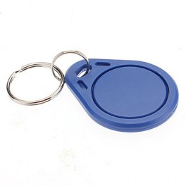
The 125KHZ RFID Key Chain is a compact and durable radio-frequency identification (RFID) device used for access control and identification applications. It operates at a frequency of 125kHz and is compatible with standard RFID readers. The key chain format makes it convenient to carry and use for various applications such as security systems, attendance tracking, and asset management.
Key Features:
- Operates at 125kHz frequency
- Durable and compact key chain design
- Compatible with standard RFID readers
- Unique identification number (UID) for each key chain
- Waterproof and shock-resistant
- Long read range (up to 10 cm depending on the reader)
- No battery required (passive RFID technology)
Technical Specifications:
- Operating Frequency: 125kHz
- Material: ABS plastic
- Dimensions: Approximately 40mm x 32mm x 4mm
- Weight: Approximately 6g
- Read Range: Up to 10 cm (depending on the reader and environment)
- Data Storage: 64-bit read-only unique identifier (UID)
- Operating Temperature Range: -25°C to +85°C
- Color: Typically blue, but may vary by manufacturer
- Waterproof: Yes
Applications:
- Access control systems
- Time and attendance tracking
- Membership management
- Asset tracking
- Secure entry systems
- Contactless payment systems
Usage:
- Integration:
- Enroll the RFID key chain in the desired RFID system by registering its unique identifier (UID) with the system’s database.
- Operation:
- Present the key chain to an RFID reader within the read range (up to 10 cm).
- The reader will capture the UID and communicate it to the control system for processing.
- Security:
- Use the key chain for secure access to restricted areas or for tracking attendance.
- Pair the key chain with a compatible RFID reader and control system for seamless operation.
Caution:
- Avoid exposing the key chain to extreme temperatures or harsh chemicals.
- Do not bend or apply excessive force to the key chain to prevent damage.
- Keep the key chain away from strong magnetic fields to ensure proper operation.
Datasheet:
For detailed technical specifications, refer to the manufacturer’s datasheet for your specific 125kHz RFID key chain model.
|
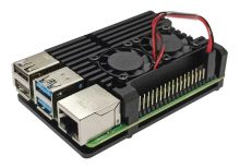
This sleek aluminum case for Raspberry Pi 4 offers superior protection and cooling with its ultra-thin design and dual cooling fans. Constructed from reinforced aluminum, the case ensures effective heat dissipation while maintaining a lightweight and durable build. The open design provides unobstructed access to all ports and does not interfere with the Wi-Fi signal.
Key Features:
- Ultra-thin Design: Slim profile for minimal space usage
- Easy Installation: Simple to assemble with included hardware
- Fast Heat Dissipation: Designed with smooth and straight aluminum material for efficient cooling
- Port Access: All ports and slots perfectly align with Raspberry Pi 4 Computer Model B
- Open Case Design: No interference with Wi-Fi signals
- Reinforced Material: Lightweight, durable aluminum with optional CPU grease for enhanced heat dissipation
- Silicon Cooling Pad: 0.5mm thickness for direct contact with the shell body, replaceable with CPU grease for better cooling
Dual Fan Features:
- Noise Level: 18dB for quiet operation
- Power Consumption: Low power design for energy efficiency
- Cooling Performance: Dual fans for enhanced heat dissipation
- Quiet Operation: Designed to minimize fan noise
- Quality Control: Each fan tested for optimal performance
- Thermal Tape: Updated for effective heat conduction
Technical Specifications:
- Material: Reinforced aluminum
- Cooling Fans: Dual 5V DC fans
- Fan Dimensions: 30mm x 30mm x 7mm
- Fan Noise Level: 18dB
- Case Dimensions: 95 x 62 x 30 mm (L x W x H)
- Weight: 150g (approx.)
- Cooling Pad Thickness: 0.5mm
- Port Compatibility: Fully compatible with Raspberry Pi 4 Model B
Applications:
- Raspberry Pi 4 Model B
- High-performance computing projects
- Media centers and home automation systems
- Robotics and DIY electronics
Usage:
- Install the Raspberry Pi 4 into the case using the provided screws and standoffs.
- Connect the dual cooling fans to the GPIO pins on the Raspberry Pi 4.
- Ensure the cooling pad or CPU grease is applied correctly for optimal heat dissipation.
Caution:
- Raspberry Pi is not included.
- Avoid exposure to excessive moisture or dust.
- Ensure fans are connected properly to avoid overheating.
|
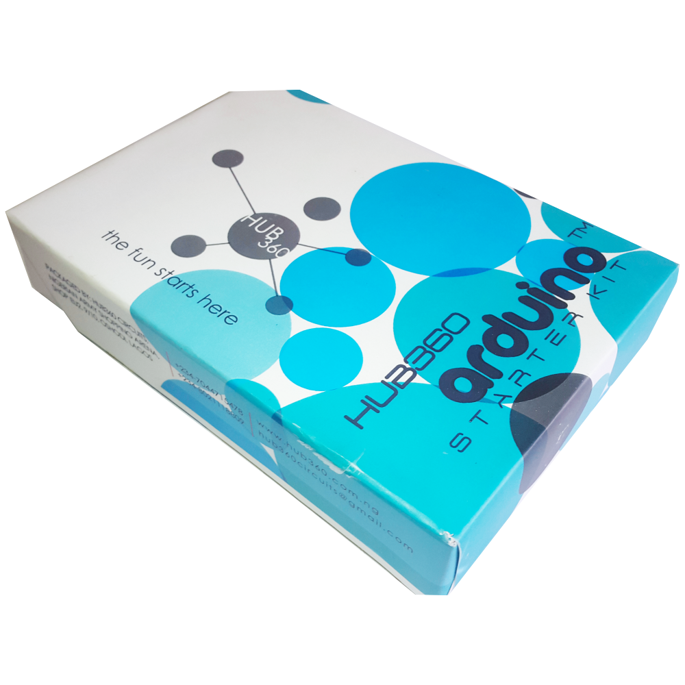
The Hub360 Arduino Starter Kit is a comprehensive package designed for beginners and enthusiasts looking to dive into the world of electronics and programming. This kit includes Arduino Uno, which is a microcontroller board based on the ATmega328P. The kit provides a variety of components and modules to help users learn and experiment with different electronic projects and concepts.
Key Features:
- Includes Arduino Uno board
- Comprehensive set of components and modules for various projects
- Ideal for beginners and hobbyists
- Detailed tutorial and project guide included
- USB interface for easy programming and power
- Compatible with Arduino IDE and various libraries
Technical Specifications:
- Microcontroller: ATmega328P
- Operating Voltage: 5V
- Input Voltage (recommended): 7-12V
- Digital I/O Pins: 14 (6 PWM outputs)
- Analog Input Pins: 6
- DC Current per I/O Pin: 20mA
- Flash Memory: 32KB (ATmega328P) of which 0.5KB used by bootloader
- SRAM: 2KB (ATmega328P)
- EEPROM: 1KB (ATmega328P)
- Clock Speed: 16 MHz
Kit Contents:
- ARDUINO BOARD 1
- ARDUINO USB CABLE 1
- ARDUINO BATTERY CONNECTOR 1
- 400 HOLE BREADBOARD 1
- LED (RED, YELLOW , GREEN, WHITE) 20
- RGB LED 1
- JUMPER WIRE(M-M, M-F, F-F) 120
- PHOTORESISTOR (LDR) 3
- MALE HEADERS 40
- ULTRASONIC SENSOR 1
- FLAME SENSOR 1
- TEMP./HUMIDITY SENSOR 1
- TILT SENSOR 1
- LASER SENSOR 1
- PIR MOTION SENSOR 1
- RESISTORS(220K, 1K, 10K,100K) 40
- 7 SEGMENT DISPLAY 1
- SG90 SERVO 1
- REMOTE CONTROL 1
- BUZZER 1
- 2N2222 2
- TSOP 1838 1
- RF TRANSMITTER 1
- RF RECEIVER 1
- TACT SWITCH 5
- 16*2 LCD DISPLAY
Applications:
- Learning basic electronics and programming
- Building interactive projects and prototypes
- Developing skills in microcontroller-based design
- Experimenting with sensors and actuators
- Creating DIY electronic devices
Usage:
- Setup:
- Connect the Arduino Uno board to your computer using the USB cable.
- Install the Arduino IDE and configure it to recognize the board.
- Programming:
- Write or upload sample code (sketches) to the Arduino board using the Arduino IDE.
- Utilize the provided components and modules to build and test different circuits.
- Experimentation:
- Follow the detailed tutorials and project guide to create various projects.
- Modify and expand on the sample projects to enhance learning and creativity.
Caution:
- Handle the components carefully to avoid damage.
- Ensure proper connections and polarity to prevent short circuits or component failure.
- Verify the code and circuit connections before powering the board.
Datasheet:
For detailed technical specifications of the Arduino Uno, refer to the Arduino Uno Datasheet.
|
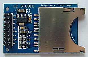
The SD Card Module is a compact and efficient solution for adding storage capabilities to your microcontroller or development board projects. It allows you to read from and write to SD cards, making it ideal for data logging, file storage, and other applications requiring large amounts of memory. The module supports various SD card formats and interfaces seamlessly with popular microcontrollers like Arduino, Raspberry Pi, and others.
Key Features:
- Storage: Supports SD, SDHC, and MicroSD (with adapter) cards
- Interface: SPI interface for easy integration
- Voltage Compatibility: Operates at 3.3V and 5V
- Onboard 3.3V Regulator: Ensures stable operation
- Card Detection: Built-in card detection switch
- Compact Design: Small footprint for easy incorporation into projects
- File System: Compatible with FAT16 and FAT32 file systems
Technical Specifications:
- Supported Cards: SD, SDHC, MicroSD (with adapter)
- Operating Voltage: 3.3V/5V
- Interface: SPI
- Current Consumption: < 100mA
- File System: FAT16, FAT32
- Dimensions: 42mm x 24mm x 12mm
Applications:
- Data Logging: Store sensor data and logs in embedded systems.
- File Storage: Save files for multimedia applications and projects.
- Firmware Updates: Load new firmware from the SD card for microcontrollers.
- DIY Projects: Perfect for hobbyists needing additional storage.
- Educational Projects: Commonly used in learning modules for data storage and retrieval.
Usage:
- Wiring: Connect the SD card module to your microcontroller using the SPI interface (CS, MOSI, MISO, SCK, VCC, GND).
- Power Supply: Ensure the module is powered with 3.3V or 5V, as required.
- Card Insertion: Insert a formatted SD card into the module.
- Programming: Use libraries (e.g., SD library for Arduino) to initialize the SD card and read/write data.
- Data Handling: Store or retrieve data files from the SD card as needed by your application.
Caution:
- Voltage Levels: Ensure proper voltage levels to avoid damaging the module.
- Handling SD Cards: Handle SD cards with care to prevent data loss or corruption.
Datasheet:
For detailed technical specifications, refer to the SD Card Module Datasheet.
|
The Professional Soldering Iron 60W is designed for precision soldering tasks in electronics and electrical work. Its high power output ensures quick heating and efficient soldering, making it ideal for both hobbyists and professionals.
Key Features:
- High Power: 60W output for fast heating and consistent performance.
- Adjustable Temperature Control: Allows precise temperature adjustments for different soldering tasks.
- Ergonomic Design: Comfortable grip for extended use and improved control.
- Fast Heat-Up: Quickly reaches operating temperature to reduce waiting time.
- Durable Tip: Long-lasting soldering tip designed for reliable performance.
Technical Specifications:
- Power: 60W
- Temperature Range: 200°C to 450°C (392°F to 842°F)
- Tip Type: Replaceable
- Handle Type: Ergonomic, heat-resistant
- Heat-Up Time: < 30 seconds
- Cord Length: 1.2 meters
- Input Voltage: 220V AC (or according to regional standards)
- Weight: Approximately 150 grams
Applications:
- Electronics assembly and repair
- PCB soldering
- Electrical connections
- Fine precision soldering work
Usage:
- Plug the soldering iron into a suitable power outlet.
- Set the desired temperature using the temperature control knob.
- Wait for the iron to reach the set temperature before using it for soldering.
- Use the soldering tip to apply solder to the joints or components as needed.
Caution:
- Handle with care as the soldering iron becomes very hot.
- Ensure proper ventilation while soldering to avoid inhaling fumes.
- Allow the soldering iron to cool down before storing.
|
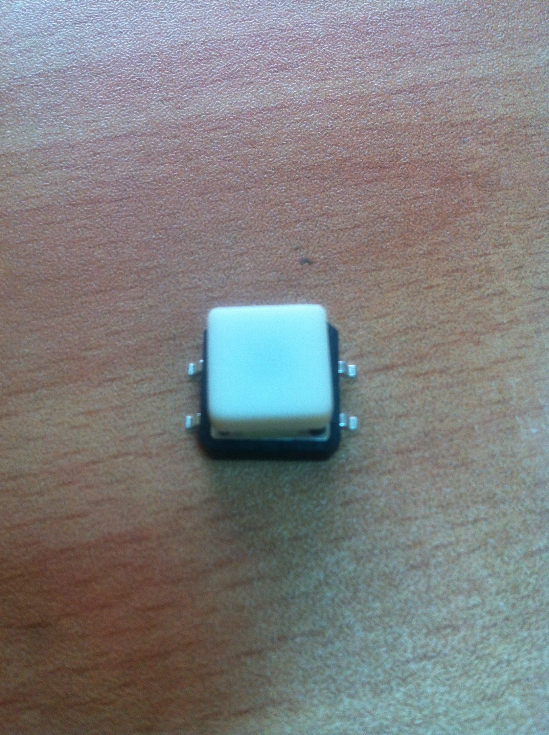
The SMD (Surface-Mount Device) tact switch with cap is a compact, reliable switch used in various electronic devices and applications. The switch is mounted directly onto a printed circuit board (PCB) and is designed to be activated by pressing the cap. The cap provides a user-friendly interface and helps in guiding the pressing action.
Key Features:
- Type: SMD Tactile Switch
- With Cap: Includes a cap for easy pressing and improved tactile feedback
- Mounting Type: Surface-mount for easy PCB integration
- Actuation Force: Typically designed for low actuation force
- Switch Function: Momentary contact (normally open; closes when pressed)
- Durability: Designed for many cycles of operation
Technical Specifications:
- Package Type: SMD (Surface-Mount Device)
- Cap Type: Plastic or rubber cap for tactile feedback
- Actuation Force: Typically ranges from 100g to 500g (varies by model)
- Contact Rating: Generally rated for 50mA to 100mA at 12V (varies by model)
- Contact Resistance: Typically 100Ω or less
- Insulation Resistance: Typically 100MΩ or more
- Life Cycle: Rated for up to 1,000,000 cycles
- Operating Temperature Range: -20°C to +85°C
Applications:
- Consumer Electronics: Used in devices like remote controls, calculators, and handheld devices
- Industrial Equipment: Integrated into control panels and user interfaces
- Automotive: Utilized in dashboards and control systems
- Medical Devices: Employed in compact medical equipment and interfaces
Usage:
- PCB Mounting: Solder the SMD tact switch to the designated pads on the PCB.
- Cap Placement: Ensure the cap is securely placed on the switch for proper operation and tactile feedback.
- Testing: Test the switch to ensure it functions correctly and provides the desired tactile response.
- Integration: Integrate the switch into the final assembly and connect it to the necessary circuits or components.
Caution:
- Handling: Handle with care to avoid damaging the switch or cap.
- Soldering: Follow proper soldering techniques to avoid overheating or damaging the switch.
- Compatibility: Ensure the switch is compatible with the design requirements and PCB layout.
Datasheet:
For detailed technical specifications and mounting guidelines, refer to the manufacturer’s datasheet for the specific SMD tact switch model.
|
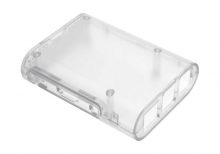
The Raspberry Pi 3 Transparent Injection Case is a protective enclosure designed for the Raspberry Pi 3 Model B and Model B+. It provides a clear, durable case that allows easy viewing of the Raspberry Pi while protecting it from dust, damage, and physical impact. The case is made from high-quality injection-molded plastic, ensuring a precise fit and a sleek, modern look.
Key Features:
- Transparent design for visibility of the Raspberry Pi board
- Injection-molded plastic construction for durability
- Precise cutouts for all ports, connectors, and GPIO pins
- Easy access to SD card slot and USB ports
- Ventilation slots for effective heat dissipation
- Simple snap-together assembly; no tools required
- Includes mounting hardware and rubber feet for stability
Technical Specifications:
- Material: Transparent injection-molded plastic
- Compatibility: Raspberry Pi 3 Model B and Model B+
- Color: Clear/Transparent
- Dimensions: Varies slightly by manufacturer (typically around 90mm x 60mm x 30mm)
- Weight: Varies slightly by manufacturer (typically around 50g)
Applications:
- Protecting Raspberry Pi 3 during use and handling
- Displaying the Raspberry Pi while maintaining access to ports
- Enclosing Raspberry Pi in a professional or educational setting
- Enhancing the aesthetics of Raspberry Pi-based projects
Usage:
- Place the Raspberry Pi 3 into the case, aligning it with the cutouts and mounting points.
- Snap the case parts together to secure the Raspberry Pi in place.
- Ensure all ports and connectors are accessible through the case openings.
- Mount the case using the included rubber feet or screws if required.
Caution:
- Handle the case carefully to avoid scratches or cracks.
- Ensure proper ventilation to prevent overheating of the Raspberry Pi.
- Verify that all connectors and ports are aligned and accessible before use.
Datasheet:
For detailed technical specifications, refer to the Raspberry Pi 3 Transparent Injection Case database.
|
