|
Description |
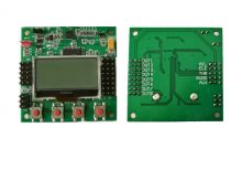
The KK 2.1.5 VTOL (Vertical Take-Off and Landing) Flight Controller is a specialized controller designed for VTOL aircraft, capable of transitioning between vertical and horizontal flight modes. It offers stabilization, control, and flexibility for multirotor and fixed-wing hybrid configurations.
Key Features:
- Flight Modes: Supports both multirotor and fixed-wing flight modes, including VTOL transitions.
- Stabilization: Provides gyroscopic stabilization for smooth flight performance.
- Configuration Options: Adjustable PID settings for fine-tuning flight characteristics.
- User Interface: LCD display for easy setup and configuration.
- Compatibility: Works with various sizes of VTOL aircraft and configurations.
- Power Management: Efficient power management features to optimize flight time.
- Expandability: Interfaces for connecting additional sensors and peripherals.
Technical Specifications:
- Flight Modes: Multirotor (quadcopter, hexacopter) and Fixed-Wing (airplane) modes
- Control Channels: Typically supports up to 6 channels for control inputs
- Gyroscopic Sensors: Integrated gyroscopic sensors for stabilization
- Processor: Microcontroller-based with sufficient processing power for flight control algorithms
- Interfaces: Connections for receivers, servos, and other flight control components
- Power Supply: Typically powered by the flight battery (e.g., LiPo)
Applications:
- VTOL Aircraft: Control and stabilization for hybrid aircraft combining vertical and horizontal flight capabilities.
- Drone Development: Essential for developing and testing VTOL drone prototypes.
- Research: Used in research projects exploring hybrid UAV technologies.
- Educational Purposes: Teaching tool for understanding flight control systems in VTOL aircraft.
- Commercial Use: Deployment in commercial drones for various applications.
Datasheet:
For detailed technical information, refer to the KK 2.1.5 VTOL Flight Controller datasheet.
|
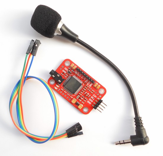
The Voice Recognition Module V3 is a compact and easy-to-use voice recognition module designed for embedded systems. It can be trained to recognize voice commands and respond accordingly, making it ideal for applications in home automation, robotics, and interactive projects. The module supports up to 80 voice commands, with 7 commands being recognized at any given time.
Key Features:
- Supports up to 80 voice commands
- Recognizes 7 voice commands simultaneously
- Speaker-independent and speaker-dependent modes
- Easy UART interface for communication with microcontrollers
- Onboard microphone for voice input
- Low power consumption
- Supports multiple languages
- High accuracy and fast response time
Technical Specifications:
- Supply Voltage: 4.5V to 5.5V
- Current Consumption: 50 mA (max)
- Interface: UART (9600 bps default)
- Recognition Accuracy: 99%
- Recognition Time: < 1 second
- Number of Commands: 80 (in groups of 7)
- Operating Temperature Range: -40°C to +85°C
- Dimensions: 30mm x 20mm x 5mm
Applications:
- Home automation systems
- Voice-controlled robots
- Interactive toys and games
- Voice-activated devices
- Security systems
- Assistive technologies for the disabled
Usage:
- Connection:
- Connect the VCC pin to a 5V power supply.
- Connect the GND pin to ground.
- Connect the RX pin to the TX pin of the microcontroller.
- Connect the TX pin to the RX pin of the microcontroller.
- Training:
- Use the provided software or serial commands to train the module with voice commands.
- Train the module in a quiet environment for best results.
- Store the voice commands in one of the available groups.
- Operation:
- After training, the module can recognize voice commands and send corresponding signals to the microcontroller.
- Use the recognized commands to control devices, trigger actions, or execute programs.
- Programming:
- Write a program on the microcontroller to interface with the module and handle recognized commands.
- Use the UART interface to send and receive data from the module.
Caution:
- Avoid exposing the module to high levels of noise during operation.
- Handle the module carefully to avoid damage from electrostatic discharge (ESD).
- Ensure proper power supply and connections to prevent malfunction.
Datasheet:
For detailed technical specifications, refer to the Voice Recognition Module V3 Datasheet.
|
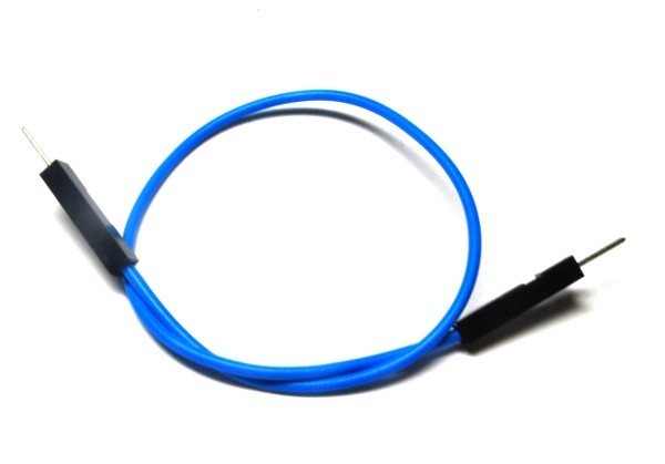
A single male-male jumper wire features male connectors on both ends and is used for making connections between components, breadboards, and other circuit boards. These wires are essential in prototyping and development for creating temporary circuits or testing designs. They allow for easy and flexible connections without the need for soldering.
Key Features:
- Connectors: Male connectors on both ends
- Wire Type: Flexible, insulated wire for easy handling and routing
- Length: Available in various lengths to suit different project needs
- Color-Coded: Available in multiple colors for easy identification and organization
- Durability: Made from high-quality materials for reliable and repeated use
- Compatibility: Suitable for standard 2.54mm (0.1 inch) pitch headers and connectors
Technical Specifications:
- Connector Type: Male-to-male
- Wire Gauge: Typically 28 AWG
- Insulation Material: PVC or similar flexible plastic
- Pitch: 2.54mm (0.1 inch)
- Length Options: Common lengths include 10cm, 20cm, 30cm, and others
- Operating Temperature: Typically -40°C to +80°C
- Current Rating: Usually up to 1A
Applications:
- Prototyping: Ideal for making connections on breadboards and development boards.
- Educational Projects: Used in educational settings to teach electronics and programming concepts.
- DIY Electronics: Suitable for hobbyists and makers working on various electronics projects and experiments.
- Temporary Connections: Useful for creating temporary connections during development and testing.
- Interfacing Components: Facilitates connections between components and modules with male pin headers.
|
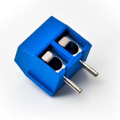
The 2-Way PCB Screw Terminal is a compact and reliable connector used to securely attach and disconnect wires on a printed circuit board (PCB). It features two screw terminals for connecting two wires, providing a stable and durable connection for various electronic and electrical applications. This type of terminal is commonly used in power distribution, signal connections, and modular systems.
Key Features:
- Two screw terminals for easy wire connection
- Suitable for use with PCB for secure mounting
- Provides a reliable and durable electrical connection
- Simple and convenient for quick wire insertion and removal
- Supports various wire gauges and types
- Compact design for space-saving on PCB
Technical Specifications:
- Number of Positions: 2
- Terminal Type: Screw
- Mounting Type: PCB (Printed Circuit Board)
- Wire Gauge Range: Typically 22-12 AWG (varies by manufacturer)
- Insulation Material: Polyamide (PA) or other suitable insulating materials
- Terminal Material: Brass or copper with tin plating
- Operating Voltage: Typically up to 300V (depends on the specific terminal rating)
- Operating Temperature Range: -40°C to +105°C
- Package Type: Typically available in strips or individual connectors
Applications:
- Power supply connections
- Signal wiring and distribution
- Modular and expandable systems
- Industrial equipment
- Consumer electronics
Usage:
- Mount the 2-Way PCB Screw Terminal onto the PCB by inserting it into the designated holes.
- Secure the terminal to the PCB by soldering the pins or using mechanical locking methods (if applicable).
- Strip the insulation from the wires to the appropriate length.
- Insert the stripped wires into the terminal and tighten the screws to secure the wires in place.
Caution:
- Ensure the terminal is rated for the voltage and current levels used in your application.
- Avoid over-tightening the screws to prevent damage to the terminal or wires.
- Verify proper wire insulation stripping to ensure reliable connections.
Datasheet:
For detailed technical specifications, refer to the 2-Way PCB Screw Terminal Datasheet.
|
A set of male-female jumper wires includes multiple wires, each with a male connector on one end and a female connector on the other. These wires are commonly used in electronic prototyping and development to establish connections between components, breadboards, and circuit boards. The set typically comes in a variety of lengths and colors, making it versatile and easy to manage for various project needs.
Key Features:
- Connectors: Male connector on one end and female connector on the other
- Wire Type: Flexible, insulated wire for easy routing and manipulation
- Length Options: Set often includes wires of various lengths to suit different applications
- Color-Coded: Available in multiple colors for easy identification and organization
- Durability: High-quality materials for reliable and repeated use
- Compatibility: Fits standard 2.54mm (0.1 inch) pitch headers and connectors
Technical Specifications:
- Connector Type: Male-to-female
- Wire Gauge: Typically 28 AWG
- Insulation Material: PVC or similar flexible plastic
- Pitch: 2.54mm (0.1 inch)
- Length Options: Common lengths in the set may include 10cm, 20cm, 30cm, etc.
- Operating Temperature: Typically -40°C to +80°C
- Current Rating: Usually up to 1A
Applications:
- Prototyping: Ideal for creating and modifying circuits on breadboards and development boards.
- Educational Projects: Used for teaching and learning electronics and programming.
- DIY Electronics: Perfect for hobbyists working on various electronics projects and experiments.
- Temporary Connections: Useful for making temporary connections during the development and testing phases.
- Interfacing Modules: Facilitates connections between male pin headers and female sockets on different electronic modules and components.
|
The 125KHZ RFID Card is a contactless proximity card used for various identification and access control applications. It operates at a frequency of 125kHz and contains a unique identification number (UID) for each card. This card is durable and convenient, making it ideal for use in security systems, time and attendance tracking, and membership management.
Key Features:
- Operates at 125kHz frequency
- Durable PVC material
- Compatible with standard 125kHz RFID readers
- Unique identification number (UID) for each card
- Waterproof and tamper-resistant
- Long read range (up to 10 cm depending on the reader)
- No battery required (passive RFID technology)
Technical Specifications:
- Operating Frequency: 125kHz
- Material: PVC plastic
- Dimensions: 85.6mm x 54mm x 0.8mm (standard credit card size)
- Weight: Approximately 6g
- Read Range: Up to 10 cm (depending on the reader and environment)
- Data Storage: 64-bit read-only unique identifier (UID)
- Operating Temperature Range: -25°C to +85°C
- Color: Typically white, but may vary by manufacturer
- Waterproof: Yes
Applications:
- Access control systems
- Time and attendance tracking
- Membership management
- Asset tracking
- Secure entry systems
- Contactless payment systems
Usage:
- Integration:
- Enroll the RFID card in the desired RFID system by registering its unique identifier (UID) with the system’s database.
- Operation:
- Present the card to an RFID reader within the read range (up to 10 cm).
- The reader will capture the UID and communicate it to the control system for processing.
- Security:
- Use the card for secure access to restricted areas or for tracking attendance.
- Pair the card with a compatible RFID reader and control system for seamless operation.
Caution:
- Avoid exposing the card to extreme temperatures or harsh chemicals.
- Do not bend or apply excessive force to the card to prevent damage.
- Keep the card away from strong magnetic fields to ensure proper operation.
Datasheet:
For detailed technical specifications, refer to the manufacturer’s datasheet for your specific 125kHz RFID card model.
|
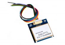
The VK2828 G28U7FTTL is a high-performance GPS module designed for aviation and other high-precision applications. It features a wide range of operational frequencies and is capable of delivering accurate positional data for navigation and tracking purposes. The module is ideal for integration into systems requiring reliable and precise GPS information.
Key Features:
- High Update Rate: Capable of updating position data from 1Hz to 10Hz, allowing for smooth and accurate tracking
- Sensitivity: Designed for use in aviation, providing robust performance in various environmental conditions
- Compatibility: Supports standard GPS protocols for easy integration into existing systems
- Compact Size: Suitable for integration into space-constrained applications
Technical Specifications:
- Type: GPS Module
- Model: VK2828 G28U7FTTL
- Update Rate: 1Hz to 10Hz
- Frequency Range: Supports standard GPS frequencies
- Sensitivity: High sensitivity for accurate positioning
- Protocol: NMEA-0183
- Operating Voltage: Typically 3.3V to 5V DC
- Power Consumption: Low power consumption for battery-operated applications
- Dimensions: Varies by model, generally compact for easy integration
- Antenna: May include an external or integrated antenna depending on the model
Applications:
- Aviation: Navigation and tracking for aircraft
- Marine: Boat and ship navigation
- Automotive: Advanced driver-assistance systems (ADAS)
- Outdoor Activities: Hiking and sports tracking
- Industrial: Asset tracking and fleet management
Usage:
- Powering the Module: Connect the GPS module to a suitable power source within the specified voltage range.
- Connecting the Antenna: Ensure the antenna is properly connected and positioned for optimal signal reception.
- Data Integration: Use the NMEA protocol to receive GPS data, including latitude, longitude, altitude, and time.
- Integration: Connect the GPS module to your system or application for real-time tracking and navigation.
Caution:
- Signal Reception: Ensure the module has a clear view of the sky for optimal GPS signal reception.
- Voltage: Verify the operating voltage to avoid damage to the module.
- Antenna Placement: Position the antenna to minimize interference and maximize signal strength.
Datasheet:
For detailed technical specifications, refer to the VK2828 G28U7FTTL Datasheet .
|
The PIR (Passive Infrared) Motion Sensor is a reliable and efficient sensor used to detect motion by measuring changes in infrared radiation levels emitted by surrounding objects. It is widely used in security systems, automatic lighting controls, and other applications requiring motion detection. The sensor is designed to detect human movement and can trigger alarms, lights, or other systems in response to detected motion.
Key Features:
- Type: Passive Infrared (PIR) motion sensor
- Detection Range: Up to 7 meters
- Detection Angle: 120 degrees
- Output: Digital high/low signal
- Operating Voltage: 5V to 20V
- Adjustable Sensitivity: Allows customization of detection range
- Adjustable Time Delay: Configurable delay before resetting
- Compact Design: Small and easy to integrate into various systems
Technical Specifications:
- Operating Voltage: 5V to 20V
- Current Consumption: < 60µA
- Output Type: Digital (high/low)
- Detection Range: Up to 7 meters
- Detection Angle: 120 degrees
- Trigger Time: Adjustable from 5 seconds to 5 minutes
- Operating Temperature Range: -20°C to +50°C
- Dimensions: 32mm x 24mm
Applications:
- Security Systems: Use in burglar alarms and surveillance systems.
- Automatic Lighting: Control lights in homes, offices, and public spaces.
- Energy Saving: Automate lighting and devices to save energy.
- Consumer Electronics: Motion-activated gadgets and appliances.
- Industrial Automation: Detect movement in industrial processes and machinery.
Usage:
- Installation: Mount the PIR sensor at the desired location, ensuring a clear line of sight for detection.
- Power Supply: Connect the sensor to a power source within the operating voltage range.
- Output Connection: Connect the output pin to the desired control circuit or microcontroller.
- Adjustment: Use the sensitivity and time delay adjustments to fine-tune the sensor’s performance.
Caution:
- Environmental Factors: Avoid placing the sensor near heat sources or in direct sunlight to prevent false triggering.
- Proper Wiring: Ensure correct wiring to avoid damage to the sensor and connected devices.
Datasheet:
For detailed technical specifications, refer to the PIR Motion Sensor Datasheet.
|
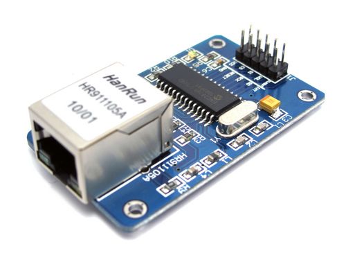
The ENC28J60 Ethernet Network Board Module is a compact and efficient solution for adding Ethernet connectivity to microcontroller-based projects. It features the ENC28J60 Ethernet controller from Microchip Technology, which is a standalone Ethernet controller with an SPI interface. This module is ideal for embedded systems that require network communication capabilities, such as IoT devices, web servers, and home automation systems.
Key Features:
- ENC28J60 Ethernet controller chip
- Supports 10Mbps data rate
- SPI interface for easy integration with microcontrollers
- Built-in MAC and PHY layer
- Low power consumption
- Compact design with RJ45 connector and status LEDs
- Compatible with various microcontroller platforms
Technical Specifications:
- Ethernet Controller: ENC28J60
- Data Rate: 10Mbps
- Interface: SPI (Serial Peripheral Interface)
- Operating Voltage: 3.3V
- Current Consumption: Typically 180mA
- Connector Type: RJ45 Ethernet connector
- Dimensions: Typically 48mm x 24mm x 15mm (varies slightly by manufacturer)
- Operating Temperature Range: -40°C to +85°C
Applications:
- IoT (Internet of Things) devices
- Home automation systems
- Web servers and clients
- Networked sensors and data loggers
- Remote monitoring and control systems
- Embedded systems requiring network connectivity
Usage:
- Connect the ENC28J60 module to your microcontroller or development board using the SPI interface (CS, SCK, MISO, MOSI) and power supply (3.3V, GND).
- Use the appropriate library or driver for your microcontroller platform to initialize and configure the ENC28J60 for network communication.
- Connect the module to an Ethernet network using the RJ45 connector.
- Implement network communication protocols and functions in your application code to interact with other devices or servers over the network.
- Monitor the status LEDs on the module for network activity and connection status.
Caution:
- Ensure the power supply voltage is 3.3V to avoid damaging the module.
- Verify SPI connections and configuration settings for proper communication with the microcontroller.
- Handle the module carefully to avoid damage to the electronic components and connectors.
Datasheet:
For detailed technical specifications, refer to the ENC28J60 Datasheet.
|
The LiPo Battery 7.4V 2400mAh is a rechargeable lithium polymer battery commonly used in high-performance applications such as drones, RC vehicles, and other electronics. Its high capacity and stable voltage make it suitable for applications requiring reliable and extended power supply. This battery offers a balance between size, weight, and power output.
Key Features:
- Voltage: 7.4V (nominal)
- Capacity: 2400mAh
- Chemistry: Lithium Polymer (LiPo)
- Discharge Rate: Typically high discharge rates available (e.g., 20C to 30C)
- Charge Rate: Safe charging rate, typically 1C (2400mA)
- Compact Design: Lightweight and compact for easy integration
- Protection Circuit: Often includes built-in protection to prevent overcharging and over-discharging (varies by manufacturer)
Technical Specifications:
- Dimensions:
- Length: 100 mm (typical)
- Width: 35 mm (typical)
- Height: 15 mm (typical)
- Weight: Approximately 150 g
- Nominal Voltage: 7.4V
- Capacity: 2400mAh
- Discharge Rate:
- Continuous: Typically 20C to 30C (e.g., 48A to 72A)
- Peak: Higher rates available depending on model
- Charge Rate: 1C (2400mA) or as specified by manufacturer
- Connector Type: JST or XT60 (varies by model)
- Battery Type: Lithium Polymer (LiPo)
- Protection Circuit: Built-in protection (varies by model)
Applications:
- Drones: Provides power for multirotor drones and other UAVs.
- RC Vehicles: Suitable for remote-controlled cars, boats, and planes.
- Electronics Projects: Ideal for DIY electronics and prototyping projects requiring reliable power.
- High-Power Devices: Used in devices requiring high discharge rates and extended battery life.
Datasheet:
For detailed technical information, refer to the LiPo Battery 7.4V 2400mAh Datasheet.
|
The T Plug Pair, also known as Deans connectors, is a set of high-current connectors commonly used in RC models, batteries, and other electronic applications requiring reliable and secure power connections. These connectors are known for their low resistance, high current carrying capacity, and easy-to-use design.
Key Features:
- Type: T Plug (Deans connectors)
- Current Capacity: High current capacity for demanding applications
- Design: Compact design for ease of use and installation
- Material: High-quality plastic housing with gold-plated metal contacts for improved conductivity and durability
- Polarity: Clearly marked to prevent incorrect connections
- Compatibility: Widely compatible with RC batteries, ESCs, and other electronic devices
Technical Specifications:
- Dimensions:
- Length: Approximately 15 mm
- Width: Approximately 8 mm
- Height: Approximately 20 mm
- Weight: Approximately 2-3 g per connector
- Material:
- Contacts: Gold-plated for low resistance and high conductivity
- Housing: Heat-resistant plastic
- Current Rating: Up to 60A continuous (varies by manufacturer)
- Voltage Rating: Typically up to 20V
- Connection Type: Soldered connections for secure attachment to wires
Applications:
- RC Models: Commonly used in RC cars, boats, airplanes, and drones for connecting batteries to ESCs and motors.
- Batteries: Ideal for making secure connections between batteries and electronic devices.
- DIY Electronics: Useful for hobbyists and engineers working on custom electronic projects requiring reliable power connections.
- Power Systems: Suitable for high-current applications in various power systems and electronic setups.
Datasheet:
For detailed technical information, refer to the T Plug Pair Datasheet.
|
The LMV321IDBVR is a low power operational amplifier designed for general-purpose applications where low voltage, low power consumption, and small package size are critical.
Key Features:
- Supply Voltage: Typically operates from 2.7V to 5.5V.
- Low Quiescent Current: Helps in conserving power, suitable for battery-operated devices.
- Low Offset Voltage: Provides accurate amplification of small signals.
- Single Supply Operation: Suitable for applications with single power supply voltage.
- Rail-to-Rail Output: Capable of driving signals close to both supply rails.
- Small Package: Available in SOT-23-5 package, suitable for space-constrained applications.
Technical Specifications:
- Number of Channels: Single operational amplifier.
- Bandwidth: Typically ranges up to several MHz.
- Slew Rate: Provides fast response to input signals.
- Input Offset Voltage: Low input offset voltage for precision applications.
- Temperature Range: Typically operates from -40°C to +125°C.
- Applications: Ideal for battery-powered devices, sensor interfaces, signal conditioning, and portable electronics.
Datasheet:
For detailed technical information, refer to the LMV321IDBVR Datasheet.
|
