|
Description |
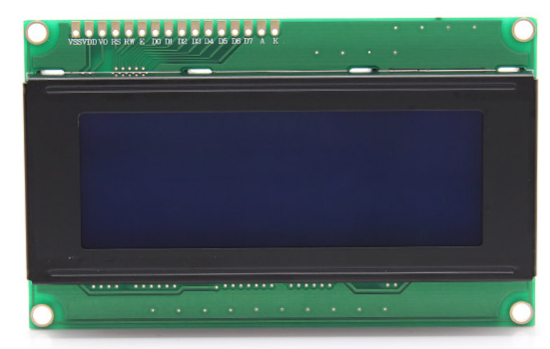
The LCD 2004 module is a 20×4 character Liquid Crystal Display that provides a simple and effective way to display text, numbers, and custom characters in embedded systems and microcontroller projects. It features an I2C interface for easy integration and communication, reducing the number of required GPIO pins. The backlit display ensures readability in various lighting conditions.
Key Features:
- 20 characters by 4 lines display
- I2C interface for easy connectivity
- Blue backlight with white text
- Adjustable contrast via a potentiometer
- Low power consumption
- Compatible with various microcontroller platforms (e.g., Arduino, Raspberry Pi)
Technical Specifications:
- Display Type: Character LCD
- Characters: 20 characters x 4 lines
- Interface: I2C
- Operating Voltage: 5V
- Backlight: Blue with white text
- Dimensions: Approximately 98mm x 60mm x 12mm
- Viewing Area: 76mm x 25.2mm
- Character Size: 4.84mm x 9.66mm
- Controller: HD44780 or equivalent
Applications:
- Embedded systems
- Microcontroller projects
- Industrial control displays
- Home automation systems
- Instrumentation panels
- Educational and learning projects
Usage:
- Connection:
- Connect the VCC and GND pins to the 5V and GND of the microcontroller.
- Connect the SDA (data) and SCL (clock) pins to the corresponding I2C pins on the microcontroller.
- Programming:
- Use an appropriate library (e.g., LiquidCrystal_I2C for Arduino) to initialize and control the display.
- Write code to display text, numbers, and custom characters as needed.
- Adjust Contrast:
- Use the onboard potentiometer to adjust the contrast of the display for optimal readability.
- Backlight Control:
- Control the backlight through software if supported by the library or manually via the backlight pin.
Caution:
- Ensure the power supply voltage is 5V to avoid damaging the module.
- Handle the module carefully to avoid damage to the display and the I2C pins.
- Verify the I2C address and adjust in the code if necessary, as some modules may have different default addresses.
Datasheet:
For detailed technical specifications, refer to the LCD 2004 Module Datasheet.
|
The Professional Soldering Iron 60W is designed for precision soldering tasks in electronics and electrical work. Its high power output ensures quick heating and efficient soldering, making it ideal for both hobbyists and professionals.
Key Features:
- High Power: 60W output for fast heating and consistent performance.
- Adjustable Temperature Control: Allows precise temperature adjustments for different soldering tasks.
- Ergonomic Design: Comfortable grip for extended use and improved control.
- Fast Heat-Up: Quickly reaches operating temperature to reduce waiting time.
- Durable Tip: Long-lasting soldering tip designed for reliable performance.
Technical Specifications:
- Power: 60W
- Temperature Range: 200°C to 450°C (392°F to 842°F)
- Tip Type: Replaceable
- Handle Type: Ergonomic, heat-resistant
- Heat-Up Time: < 30 seconds
- Cord Length: 1.2 meters
- Input Voltage: 220V AC (or according to regional standards)
- Weight: Approximately 150 grams
Applications:
- Electronics assembly and repair
- PCB soldering
- Electrical connections
- Fine precision soldering work
Usage:
- Plug the soldering iron into a suitable power outlet.
- Set the desired temperature using the temperature control knob.
- Wait for the iron to reach the set temperature before using it for soldering.
- Use the soldering tip to apply solder to the joints or components as needed.
Caution:
- Handle with care as the soldering iron becomes very hot.
- Ensure proper ventilation while soldering to avoid inhaling fumes.
- Allow the soldering iron to cool down before storing.
|
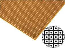
A small size dotted Vero board, also known as a stripboard or prototyping board, is a type of circuit board that is used for prototyping and building electronic circuits. It features a grid of holes with copper pads that allow components to be easily soldered onto the board. The dotted pattern provides flexibility in layout, making it ideal for custom circuit designs and small electronic projects.
Key Features:
- Dotted pattern for versatile circuit layout
- High-quality FR4 material for durability
- Copper pads for easy soldering
- Small size for compact projects
- Compatible with through-hole components
- Suitable for prototyping and custom circuit building
Technical Specifications:
- Material: FR4 (fiberglass epoxy laminate)
- Size: Typically around 70mm x 90mm (varies by manufacturer)
- Hole Pitch: 2.54mm (standard 0.1 inch grid)
- Hole Diameter: 1.0mm (suitable for most through-hole components)
- Thickness: 1.6mm
- Copper Thickness: 35µm (1oz/ft²)
- Pattern: Dotted (individual copper pads)
- Number of Holes: Varies by board size (e.g., 25×35 grid for 70mm x 90mm board)
Applications:
- Prototyping electronic circuits
- Custom circuit design
- DIY electronics projects
- Educational and learning purposes
- Small-scale production of custom circuits
Usage:
- Design the Circuit:
- Plan the layout of your components and connections on the Vero board.
- Place the Components:
- Insert the components into the holes according to your circuit design.
- Solder the Components:
- Solder the component leads to the copper pads on the reverse side of the board.
- Create Connections:
- Use solder bridges or wire links to create electrical connections between the copper pads as needed.
- Test the Circuit:
- Verify the circuit functionality and make any necessary adjustments or corrections.
Caution:
- Ensure proper soldering techniques to avoid short circuits or poor connections.
- Handle the board carefully to avoid damaging the copper pads or FR4 material.
- Verify the component placement and connections before powering the circuit.
|
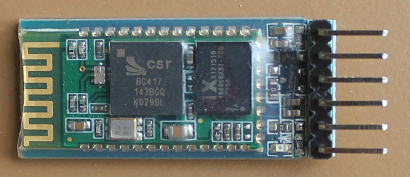
The HC-05 Bluetooth module is a versatile and user-friendly wireless communication device designed for seamless integration with microcontrollers and embedded systems. It supports Bluetooth 2.0+EDR (Enhanced Data Rate) and provides reliable and efficient wireless data transmission. The module is commonly used in wireless control and data exchange applications, including home automation, robotics, and wireless sensor networks.
Key Features:
- Supports Bluetooth 2.0+EDR
- Easy to integrate with microcontrollers via UART interface
- Supports master and slave modes
- Built-in antenna for reliable wireless communication
- Configurable via AT commands
- LED indicators for connection status
- Low power consumption
Technical Specifications:
- Bluetooth Version: 2.0+EDR
- Frequency Range: 2.4GHz ISM band
- Operating Voltage: 3.3V to 5V
- Communication Protocol: UART (default baud rate: 9600 bps)
- Range: Up to 10 meters (unobstructed)
- Power Consumption: 30mA in active mode, 8mA in idle mode
- Dimensions: 37mm x 15mm x 3mm (varies slightly by manufacturer)
- Operating Temperature Range: -20°C to +75°C
Applications:
- Wireless control of devices
- Data exchange between microcontrollers and smartphones
- Home automation systems
- Robotics and RC projects
- Wireless sensor networks
- Prototyping and educational projects
Usage:
- Connect the HC-05 module to your microcontroller or development board using the UART interface (TX, RX, VCC, and GND pins).
- Power the module with a voltage within the specified range (3.3V to 5V).
- Use AT commands to configure the module’s settings, such as baud rate, mode (master/slave), and pairing details.
- Pair the HC-05 module with another Bluetooth-enabled device (e.g., smartphone, PC) to establish a wireless connection.
- Exchange data between the paired devices via the UART interface.
Caution:
- Ensure the power supply voltage is within the specified range to avoid damaging the module.
- Handle the module carefully to avoid physical damage to the components and antenna.
- Verify the UART connections to ensure proper communication between the module and the microcontroller.
Datasheet:
For detailed technical specifications, refer to the HC-05 Datasheet.
|
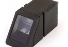
The AS608 Optical Fingerprint Module is a compact and efficient fingerprint recognition device designed for integration into security systems. It uses optical fingerprint sensing technology to capture and store fingerprint data, providing high accuracy and reliability in biometric authentication. The module is suitable for various applications, including access control, time attendance systems, and personal identification.
Key Features:
- High-precision optical fingerprint sensor
- Fast and accurate fingerprint recognition
- Supports fingerprint storage and matching
- Easy to integrate with microcontrollers and development boards
- Low power consumption
- Built-in algorithm for fingerprint processing
- UART interface for communication
Technical Specifications:
- Supply Voltage: 3.6V to 6V DC
- Operating Current: <120mA
- Fingerprint Capacity: 162 templates
- Verification Time: <1 second
- False Acceptance Rate (FAR): <0.001%
- False Rejection Rate (FRR): <0.1%
- Interface: UART (TTL logic level)
- Communication Speed: 9600 baud (default, adjustable)
- Working Temperature: -20°C to 50°C
- Dimensions: 32mm x 32mm x 10mm
- Weight: 20g
Applications:
- Access control systems
- Time attendance systems
- Personal identification devices
- Biometric authentication systems
- Safe and locker systems
- IoT security applications
Usage:
- Connect the module to a microcontroller or development board using the UART interface.
- Supply the appropriate voltage to power the module.
- Use the provided library or code examples to enroll and verify fingerprints.
- Integrate the fingerprint matching results into your security system.
Caution:
- Avoid exposing the sensor to direct sunlight or intense light.
- Keep the sensor clean for optimal performance.
- Handle the module with care to prevent damage to the optical sensor.
Datasheet:
For detailed technical specifications, refer to the AS608 Optical Fingerprint Module Datasheet.
|
The ACS712 is a current sensor from Allegro Microsystems designed to measure current with a maximum rating of 30A. It provides an analog output voltage that is proportional to the current flowing through the sensor. The ACS712 is widely used in power monitoring, load current measurement, and over-current protection applications due to its high accuracy and ease of integration with microcontrollers and other electronic systems.
Key Features:
- Measures AC and DC current up to 30A
- Provides an analog output voltage proportional to the current
- High accuracy with low offset and temperature drift
- Integrated Hall effect sensor for non-invasive current measurement
- Small size and easy to integrate into various circuits
- On-chip signal conditioning and protection
Technical Specifications:
- Sensor Type: Hall Effect Current Sensor
- Current Range: ±30A (AC or DC)
- Output Voltage Range: Typically 0V to Vcc
- Sensitivity: 66mV/A (typical)
- Operating Voltage: 5V ±5%
- Zero Current Offset Voltage: Vcc/2 (typical)
- Temperature Range: -40°C to +85°C
- Current Measurement Accuracy: ±1.5% of full-scale current (typical)
- Package Type: SOP-8 or similar
Applications:
- Power monitoring and control
- Over-current protection systems
- Load current measurement in power supplies
- Motor current sensing
- Energy monitoring and management
Usage:
- Connect the ACS712 sensor to your microcontroller or development board, ensuring correct connection of the power supply (Vcc, GND) and the output voltage pin.
- Route the current-carrying conductor through the sensor to measure the current.
- Read the analog output voltage, which is proportional to the current, and process it according to your application needs.
- Calibrate the sensor if necessary to ensure accurate current measurement.
Caution:
- Ensure the current flowing through the sensor does not exceed the maximum rating (30A) to avoid damage.
- Properly insulate and protect the sensor and connections to prevent short circuits and ensure safe operation.
- Verify the power supply voltage and connections to avoid incorrect readings or sensor damage.
Datasheet:
For detailed technical specifications, refer to the ACS712 Datasheet.
|
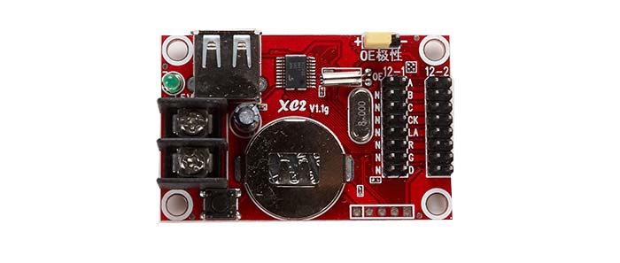
The XC2 is a versatile and high-performance integrated circuit (IC) designed for specific applications in electronic systems. While the specific functionality and details can vary depending on the exact model and manufacturer, the XC2 series typically includes features such as advanced processing capabilities, flexible I/O options, and support for a range of communication protocols. This series is used in various applications requiring efficient data handling, control, and signal processing.
Key Features:
- High-speed processing capabilities
- Flexible I/O options
- Support for multiple communication protocols
- Low power consumption
- Reliable performance in demanding environments
- Available in various package types
Technical Specifications:
- Package Type: Varies by model (e.g., TQFP, BGA)
- Operating Voltage: Typically 3.3V or 5V (depends on specific model)
- Clock Speed: Varies by model
- Memory: Varies by model (e.g., Flash, SRAM)
- I/O Pins: Varies by model
- Communication Interfaces: UART, SPI, I2C, etc. (depends on specific model)
- Operating Temperature Range: Varies by model
Applications:
- Embedded systems
- Industrial automation
- Consumer electronics
- Communication devices
- Automotive control systems
- Medical devices
Usage:
- Program the XC2 IC using the appropriate programming tools and software.
- Connect external peripherals and components to the IC’s I/O pins as required by your application.
- Configure the IC’s settings and features through software or hardware interfaces.
- Integrate the IC into your circuit and ensure proper functionality through testing.
Caution:
- Check the specific datasheet for detailed specifications and handling instructions for the XC2 model you are using.
- Ensure compatibility with your circuit’s voltage and current requirements.
- Handle with care to avoid damage from electrostatic discharge (ESD).
|
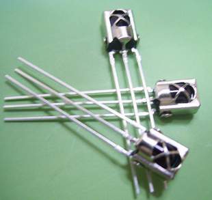
The TSOP 1838 is a compact IR (Infrared) receiver module designed for use in remote control systems. It can detect modulated IR signals at 38 kHz, making it ideal for applications such as remote control reception, IR data transmission, and IR-based communication systems. The TSOP 1838 provides high sensitivity and reliable performance in a small package.
Key Features:
- Pin diode and preamplifier in one package
- Modulated IR signal detection at 38 kHz
- High sensitivity and excellent noise immunity
- Low power consumption
- TTL and CMOS compatible output
- Internal filter for PCM frequency
- Improved shielding against electrical field disturbance
- Suitable for continuous and burst data transmission
Technical Specifications:
- Carrier Frequency: 38 kHz
- Supply Voltage: 2.7V to 5.5V
- Supply Current: 0.4 mA (typical)
- Peak Wavelength: 940 nm
- Reception Range: Up to 45 meters (with proper IR transmitter)
- Viewing Angle: ±45 degrees
- High-Level Output Voltage: ≥ Vcc – 0.2V
- Low-Level Output Voltage: ≤ 0.2V
- Output Pulse Width: Typically 400 µs
- Operating Temperature Range: -25°C to +85°C
- Package Type: 3-pin epoxy package
Applications:
- IR remote control systems
- Consumer electronics (TVs, VCRs, DVDs, audio equipment)
- Home automation
- IR data communication
- Infrared object detection
- Robotics
Usage:
- Connection:
- Connect the Vcc pin to a power supply (2.7V to 5.5V).
- Connect the GND pin to ground.
- Connect the OUT pin to the input of a microcontroller or other logic-level input device.
- Operation:
- When an IR signal at 38 kHz is received, the OUT pin goes low.
- When no IR signal is received, the OUT pin stays high.
- Use the output signal to control devices or process the data using a microcontroller.
- Interfacing:
- Interface the TSOP 1838 with a microcontroller to decode the received IR signals.
- Implement software to process the decoded IR signals for controlling various devices.
Caution:
- Ensure the IR receiver is not exposed to direct sunlight or strong ambient light sources, as this may affect its performance.
- Handle the module with care to avoid damage from electrostatic discharge (ESD).
Datasheet:
For detailed technical specifications, refer to the TSOP 1838 Datasheet.
|
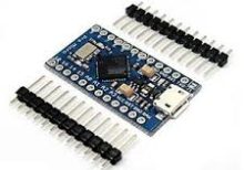
The Arduino Pro Micro is a compact and versatile microcontroller board based on the ATmega32U4 microchip. It is part of the Arduino family and designed for projects where space is limited. The Pro Micro board features built-in USB capabilities, allowing it to emulate a keyboard, mouse, or other USB devices, making it suitable for a wide range of applications including custom input devices and embedded systems.
Key Features:
- Microcontroller: ATmega32U4
- Operating Voltage: 5V
- Input Voltage (recommended): 7-12V
- Digital I/O Pins: 18
- Analog Input Pins: 9
- Flash Memory: 32 KB (ATmega32U4), of which 4 KB used by bootloader
- SRAM: 2.5 KB
- EEPROM: 1 KB
- Clock Speed: 16 MHz
- USB: Built-in USB functionality for direct connection to computers and emulation of USB devices
Technical Specifications:
- Dimensions: 33 mm x 18 mm
- Weight: Approximately 8 g
- Communication: UART, SPI, I2C, USB
- On-board LEDs: TX, RX, Power, and one user-defined LED
- Power:
- DC Current per I/O Pin: 40 mA
- DC Current for 3.3V Pin: 50 mA
- Connectors:
- USB Micro-B for programming and power
- 6-pin header for serial communication
- Pins for additional communication interfaces and power
Applications:
- Custom Input Devices: Can be used to create custom keyboards, mice, and other input devices.
- Embedded Systems: Suitable for small-scale embedded projects where USB connectivity is required.
- Prototyping: Ideal for rapid prototyping and development due to its compact size and USB capability.
- IoT Projects: Can be integrated into Internet of Things (IoT) devices for various control and monitoring applications.
- Wearables: Perfect for wearable electronics and projects requiring a small form factor.
Datasheet:
For detailed technical information, refer to the Arduino Pro Micro Datasheet.
|
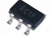
The LMV321IDBVR is a low power operational amplifier designed for general-purpose applications where low voltage, low power consumption, and small package size are critical.
Key Features:
- Supply Voltage: Typically operates from 2.7V to 5.5V.
- Low Quiescent Current: Helps in conserving power, suitable for battery-operated devices.
- Low Offset Voltage: Provides accurate amplification of small signals.
- Single Supply Operation: Suitable for applications with single power supply voltage.
- Rail-to-Rail Output: Capable of driving signals close to both supply rails.
- Small Package: Available in SOT-23-5 package, suitable for space-constrained applications.
Technical Specifications:
- Number of Channels: Single operational amplifier.
- Bandwidth: Typically ranges up to several MHz.
- Slew Rate: Provides fast response to input signals.
- Input Offset Voltage: Low input offset voltage for precision applications.
- Temperature Range: Typically operates from -40°C to +125°C.
- Applications: Ideal for battery-powered devices, sensor interfaces, signal conditioning, and portable electronics.
Datasheet:
For detailed technical information, refer to the LMV321IDBVR Datasheet.
|
A 10A 5VDC relay is an electromechanical switch that allows you to control high current circuits using a low voltage control signal. It operates on a 5V DC input and can handle up to 10A of current, making it suitable for switching various high-power loads in automation and control applications.
Key Features:
- 5V DC coil voltage
- Rated for 10A current handling
- Electromechanical switch for controlling high power circuits
- Provides electrical isolation between control and load circuits
- Compact and durable design
Technical Specifications:
- Coil Voltage: 5V DC
- Contact Rating: 10A at 250V AC / 30V DC
- Contact Configuration: Single Pole Single Throw (SPST)
- Coil Resistance: Typically 70Ω
- Operating Temperature Range: -40°C to +85°C
- Mounting Type: Typically PCB or screw terminals
Applications:
- Home automation systems
- Industrial control systems
- Automotive applications
- Power switching for household appliances
- Remote control systems
Usage:
- Connect the relay coil terminals to a 5V DC power source.
- Connect the control signal to the relay coil to activate it.
- Connect the load circuit to the relay’s normally open (NO) and common (COM) contacts.
- When the relay is energized, the NO contact will close, allowing current to flow through the load.
Caution:
- Ensure the relay’s contact rating is sufficient for the load being switched.
- Use proper insulation and safety measures to prevent electrical shock or short circuits.
- Avoid operating the relay beyond its rated specifications to ensure longevity and reliability.
Datasheet:
For detailed technical specifications, refer to the 10A 5VDC Relay Datasheet.
|
