|
Description |
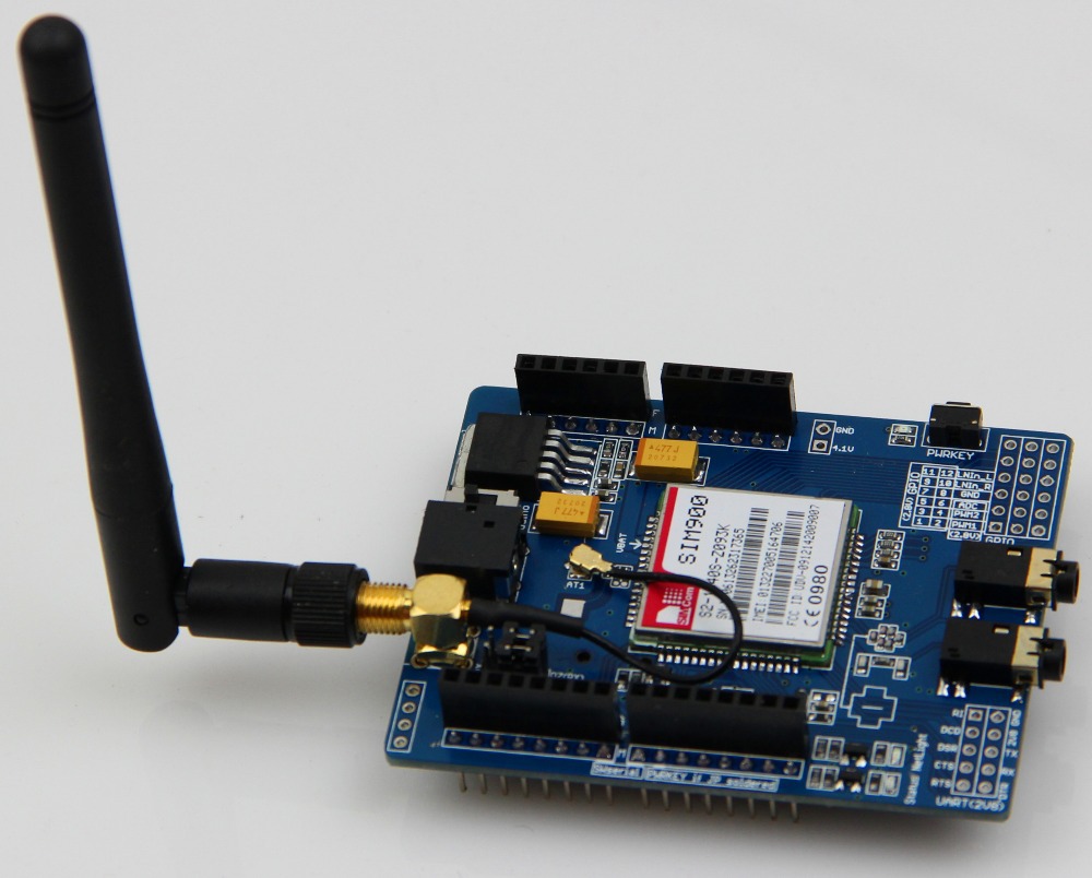
The Simcom SIM900 Shield is a quad-band GSM/GPRS shield designed for use with Arduino and other microcontroller platforms. It provides a way to add GSM communication capabilities to your project, enabling features such as SMS, voice calls, and data transfer over GPRS. The shield is compact and integrates easily into existing projects, making it ideal for IoT applications, remote monitoring, and other communication-based projects.
Key Features:
- Quad-band GSM/GPRS 850/900/1800/1900 MHz
- Supports voice calls, SMS, and GPRS data transfer
- Compatible with Arduino and other microcontroller platforms
- Integrated UART interface
- Low power consumption
- Compact design with standard Arduino shield form factor
- Built-in antenna connector
Technical Specifications:
- Operating Voltage: 5V (supplied from Arduino)
- Power Consumption:
- Idle mode: 1.5 mA
- Active mode: 250 mA (average)
- Peak: 2A
- Communication Protocols: GSM, GPRS (Class 10)
- Data Rates:
- GPRS: Up to 85.6 kbps (downlink and uplink)
- CSD: Up to 14.4 kbps
- SIM Card Slot: Standard SIM card
- UART Interface: 9600 to 115200 bps
- Operating Temperature Range: -40°C to +85°C
- Dimensions: Compatible with standard Arduino shield form factor
Applications:
- IoT projects
- Remote monitoring systems
- Home automation
- Vehicle tracking systems
- Security systems
- SMS-based control systems
- Data logging
Usage:
- Installation:
- Stack the SIM900 shield onto your Arduino board.
- Insert a standard SIM card into the SIM card slot.
- Connect an external antenna to the antenna connector if needed.
- Connection:
- Ensure the shield is properly seated on the Arduino headers.
- Connect the Arduino to a power source and a USB connection for programming.
- Programming:
- Use the SoftwareSerial library to communicate with the SIM900 module via Arduino.
- Send AT commands to control the module and perform tasks such as sending SMS, making calls, or connecting to the internet.
- Example: Initialize the module and send an SMS
- Troubleshooting:
-
- Ensure the SIM card is activated and has sufficient credit for operation.
- Check antenna connection for signal strength.
- Use the AT command AT+CSQ to check signal quality.
Caution:
- Ensure proper handling to avoid damage from electrostatic discharge (ESD).
- Verify power supply requirements to prevent damage to the module.
- Avoid placing the shield in areas with poor signal reception to ensure reliable operation.
Datasheet:
For detailed technical specifications, refer to the SIM900 Datasheet.
|
The BC547 is a versatile, general-purpose NPN bipolar junction transistor (BJT) widely used in electronic circuits for switching and amplification purposes. It is commonly found in low-power applications and is known for its reliability and ease of use. The BC547 is suitable for a variety of applications, including signal processing, amplification, and switching.
Key Features:
- General-Purpose NPN Transistor: Suitable for a wide range of applications
- Low Power Consumption: Ideal for low-power circuits
- High Gain: Provides high current gain (hFE)
- Compact Package: TO-92 package for easy integration into various designs
- High Reliability: Proven performance in diverse electronic circuits
Technical Specifications:
- Transistor Type: NPN
- Collector-Emitter Voltage (VCEO): 45V
- Collector-Base Voltage (VCBO): 50V
- Emitter-Base Voltage (VEBO): 6V
- Collector Current (IC): 100mA
- Power Dissipation (Ptot): 500mW
- DC Current Gain (hFE): 110 to 800 (depending on the model)
- Transition Frequency (fT): 300MHz
- Package Type: TO-92
- Operating Temperature Range: -55°C to +150°C
Applications:
- Signal amplification
- Switching applications
- General-purpose amplification
- Low-noise stages in audio equipment
- Sensor interfacing
- Hobby and DIY projects
Usage:
- Identify the pin configuration of the transistor: Collector (C), Base (B), and Emitter (E).
- Connect the base to the control signal through a suitable current-limiting resistor.
- Connect the emitter to ground or negative voltage rail.
- Connect the collector to the load or positive voltage rail, depending on the application.
- Ensure the power supply voltage and current ratings do not exceed the transistor’s maximum ratings.
Caution:
- Avoid exceeding the maximum voltage and current ratings to prevent damage to the transistor.
- Ensure proper heat dissipation if operating near the maximum power dissipation limit.
- Handle with care to prevent damage from electrostatic discharge (ESD).
Datasheet:
For detailed technical specifications, refer to the BC547 Datasheet.
|
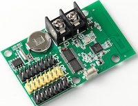
The RHX8-32W512 LED Display WiFi Control Card is a powerful control device designed for managing LED display screens with WiFi connectivity. It provides advanced features for remote control, content management, and real-time updates, making it ideal for applications requiring dynamic and flexible display solutions.
Key Features:
- Wireless Connectivity: WiFi connectivity (802.11b/g/n) for remote control and management.
- Compatibility: Compatible with a wide range of LED display screens and modules.
- Content Management: Supports uploading, scheduling, and editing of content remotely.
- Multi-screen Support: Capable of managing multiple LED screens simultaneously.
- User Interface: Intuitive web-based interface for easy configuration and operation.
- Real-time Updates: Allows instant updates of content for dynamic display requirements.
- Compatibility: Supports various LED display protocols for seamless integration.
- Power Supply: Typically powered by a standard DC power supply (voltage and current specifications may vary).
Technical Specifications:
- Interface: WiFi (802.11b/g/n)
- Control Method: Web-based interface for configuration and content management
- Supported Devices: Compatible with various LED display modules and screens
- Operating Temperature: -20°C to +60°C
- Power Supply: DC power supply (specific voltage and current requirements may vary)
- Dimensions: Compact and suitable for integration into existing display setups
- Weight: Lightweight for ease of installation
Applications:
- Digital Signage: Used for advertising, promotions, and information display in retail, transportation, and hospitality sectors.
- Event Management: Suitable for events, exhibitions, and concerts for displaying dynamic content and event information.
- Public Information: Deployed in public spaces, stadiums, and transportation hubs for displaying schedules, directions, and announcements.
- Control Centers: Integrated into control centers for managing and monitoring multiple LED displays remotely.
Datasheet:
For detailed technical information, refer to the RHX8-32W512 LED Display WiFi Control Card Datasheet
Manufacturer: Typically specified by the brand or distributor
|
Description:
The Seven Segment High Precision Electronic Clock is a digital timekeeping device that displays the current time with high accuracy. Utilizing seven-segment LED displays, it provides a clear and easily readable representation of hours, minutes, and seconds. This clock is suitable for various applications, including industrial environments, educational settings, and personal use.
Key Features:
- High Precision Timekeeping: Ensures accurate time display with minimal drift over time.
- Seven-Segment LED Display: Provides clear and bright time readouts, easily visible from a distance.
- User-Friendly Interface: Simple controls for time setting and adjustments.
- Durable Construction: Built to withstand continuous use in various environments.
- Compact Design: Easily integrates into different spaces without occupying much room.
Technical Specifications:
- Display Type: Seven-segment LED
- Power Supply: Typically 5V DC
- Accuracy: ±1 second per month
- Operating Temperature Range: 0°C to +50°C
- Dimensions: Compact size for versatile installation options
- Weight: Lightweight design for ease of handling and mounting
Applications:
- Industrial Timing: Used in manufacturing plants and workshops for precise timekeeping.
- Educational Settings: Ideal for classrooms and laboratories for teaching time management and electronics.
- Personal Use: Suitable for home and office use to keep accurate track of time.
- Public Spaces: Can be installed in public areas such as lobbies, halls, and waiting rooms for time display.
|
This 8mm deep hole linear potentiometer knob cap is designed for use with linear potentiometers in audio amplifiers and mixers. It offers a precise fit and a comfortable grip for adjusting volume, tone, and other settings on various audio equipment. The knob cap enhances the user experience by providing an intuitive and tactile interface.
Key Features:
- Fitment: Designed to fit 8mm diameter potentiometer shafts
- Material: High-quality plastic or metal, providing durability and a premium feel
- Design: Deep hole design for a secure and stable attachment
- Grip: Textured or smooth surface for comfortable and precise adjustments
- Color: Available in various colors to match different equipment aesthetics
- Applications: Suitable for audio amplifiers, mixers, and other electronic devices requiring potentiometer adjustments
Technical Specifications:
- Diameter: 8mm (shaft diameter compatibility)
- Height: Typically 15-25mm depending on the model
- Material: Plastic (ABS, PC) or metal (aluminum, brass)
- Mounting: Press-fit or set screw for secure attachment to the potentiometer shaft
- Finish: Smooth, matte, or glossy finish for different aesthetic preferences
- Temperature Range: -20°C to +80°C, ensuring reliable performance in various environments
Applications:
- Audio Amplifiers: Ideal for adjusting volume and tone settings on audio amplifiers.
- Mixers: Provides a tactile interface for controlling levels and effects on audio mixers.
- Electronic Devices: Suitable for use in various electronic devices requiring precise potentiometer adjustments.
- DIY Projects: Perfect for custom-built audio equipment and other DIY electronics projects.
|
The PIC12F509 is an 8-bit microcontroller from Microchip’s PIC series, designed for low-power and compact applications. It features a minimalistic design with essential peripherals, making it ideal for simple control tasks in embedded systems where space and power efficiency are critical.
Key Features:
- 8-bit architecture
- 1KB Flash program memory
- 64 bytes SRAM data memory
- 64 bytes Electrically Erasable Programmable Read-Only Memory (EEPROM)
- 5 I/O pins
- 8-bit Timer0
- 8-bit Watchdog Timer (WDT)
- Low-power sleep mode
Technical Specifications:
- Operating Voltage: 2.0V to 5.5V
- Operating Frequency: Up to 8MHz
- Program Memory Size: 1KB (Flash)
- Data Memory Size: 64 bytes SRAM
- EEPROM Size: 64 bytes
- Number of I/O Pins: 5
- Timers: 8-bit Timer0
- Package Type: 8-pin DIP, 8-pin SOIC
Applications:
- Low-power sensors and controls
- Simple automation tasks
- Consumer electronics
- Battery-powered devices
- Basic monitoring and logging systems
Usage:
- Connect the microcontroller to a power supply within the operating voltage range.
- Program the microcontroller using its Flash program memory for specific application tasks.
- Utilize the 5 I/O pins for interfacing with external devices.
- Implement timing functions with the 8-bit Timer0 and manage low-power states with the sleep mode.
Caution:
- Ensure the microcontroller is powered within the specified voltage range to avoid damage.
- Adhere to maximum current ratings for I/O pins.
- Handle the microcontroller carefully to prevent static discharge damage.
Datasheet:
For detailed technical specifications, refer to the PIC12F509 Datasheet.
|
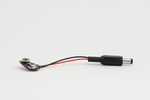
The Arduino 9V Battery Connector is a convenient accessory for powering Arduino boards and other compatible devices. It allows you to connect a standard 9V battery to the Arduino’s power jack, providing a portable power solution for your projects. This connector is essential for mobile and battery-operated applications, offering an easy and reliable way to supply power to your electronics.
Key Features:
- Compatible with standard 9V batteries
- Easy to connect and use
- Provides a secure and stable power connection
- Compact and portable design
- Durable construction for long-lasting use
- Standard DC barrel plug compatible with Arduino boards
Technical Specifications:
- Connector Type: DC barrel plug (center-positive)
- Barrel Plug Dimensions: Outer diameter 5.5mm, inner diameter 2.1mm
- Battery Connector Type: Snap-on connector for 9V battery
- Cable Length: Approximately 15 cm
- Material: Plastic and metal connectors with insulated wire
- Color: Typically black with red and black wires
Applications:
- Portable Arduino projects
- Battery-operated electronics
- Prototyping and testing
- Educational kits
- DIY electronics
Usage:
- Connection:
- Snap the 9V battery connector onto the terminals of a standard 9V battery.
- Insert the DC barrel plug into the power jack of your Arduino board or compatible device.
- Powering:
- Ensure the polarity of the connections is correct (center-positive) to avoid damage to the board.
- The Arduino will draw power from the 9V battery through the connector.
- Monitoring:
- Monitor the battery voltage periodically to ensure it remains within the acceptable range for your Arduino board (typically 7-12V).
Caution:
- Ensure the connector is securely attached to the battery terminals to prevent intermittent connections.
- Avoid short-circuiting the battery terminals.
- Do not expose the connector to moisture or extreme temperatures.
- Remove the battery from the connector when not in use to prevent battery drain.
Datasheet:
Refer to the manufacturer’s guidelines or specifications for further details.
|
The IRF9530 is a P-channel power MOSFET designed for high-efficiency switching and amplification in various electronic applications. It offers a high current and voltage rating, making it suitable for power supply circuits, motor drivers, and other high-power electronic systems.
Key Features:
- P-channel enhancement mode MOSFET
- High voltage rating: 100V
- High current rating: 12A
- Low on-resistance for efficient switching
- Fast switching speed
- Rugged and reliable construction
- Suitable for high-frequency applications
Technical Specifications:
- Type: P-channel MOSFET
- Drain-Source Voltage (Vds): -100V
- Continuous Drain Current (Id): -12A
- Pulsed Drain Current (Id, Pulse): -48A
- Gate-Source Voltage (Vgs): ±20V
- Rds(on): 0.300Ω (maximum) at Vgs = -10V
- Total Gate Charge (Qg): 59nC (typical)
- Gate-Source Threshold Voltage (Vgs(th)): -2.0V to -4.0V
- Power Dissipation (Pd): 83W
- Operating Temperature Range: -55°C to +175°C
- Package Type: TO-220
Applications:
- Switched-mode power supplies (SMPS)
- Motor control circuits
- Inverters and converters
- High-voltage DC-DC converters
- Load switches
- Audio amplifiers
- Power management systems
Usage:
- Connect the drain terminal to the high-side load or power supply.
- Connect the source terminal to the low-side or ground of the circuit.
- Apply a suitable gate voltage (Vgs) to control the switching operation.
- Use a gate resistor if needed to control the switching speed and reduce noise.
- Ensure proper heat sinking to manage power dissipation and avoid overheating.
Caution:
- Handle the MOSFET carefully to avoid damage from electrostatic discharge (ESD).
- Verify the voltage and current ratings before use to ensure compatibility with your circuit.
- Ensure adequate cooling and heat dissipation to prevent thermal overload.
Datasheet:
For detailed technical specifications, refer to the IRF9530 Datasheet.
|
The Wemos D1 WiFi UNO is a microcontroller development board that combines the features of the popular Arduino UNO with built-in WiFi capabilities, thanks to the integration of the ESP8266 module. It is designed for IoT (Internet of Things) applications, enabling easy connection to WiFi networks and interaction with cloud services or other devices over the internet.
Key Features:
- Compatible with Arduino IDE for ease of development
- Built-in WiFi connectivity via ESP8266 module
- Microcontroller based on the ESP8266 chip
- USB interface for programming and power
- 11 digital I/O pins, including 1 PWM output
- 1 analog input
- Onboard LED and reset button
- Compact design suitable for various applications
Technical Specifications:
- Microcontroller: ESP8266
- Operating Voltage: 5V DC (via USB)
- WiFi Connectivity: 802.11 b/g/n
- Digital I/O Pins: 11
- PWM Outputs: 1
- Analog Input: 1 (0-1V range)
- Flash Memory: 4 MB (typically)
- Clock Speed: 80 MHz or 160 MHz
- Package Type: Standard Arduino UNO layout
- Dimensions: Approximately 68mm x 53mm
Applications:
- Internet of Things (IoT) projects
- Home automation systems
- Wireless data logging
- Remote sensor monitoring
- Smart home devices
- Educational projects in electronics and programming
Usage:
- Connect the Wemos D1 WiFi UNO to your computer via the USB interface.
- Install the necessary drivers and Arduino IDE with the ESP8266 board support package.
- Write and upload your code using the Arduino IDE, leveraging the WiFi capabilities to connect to networks or web services.
- Use the digital I/O pins, analog input, and onboard LED in your projects according to your needs.
- Monitor and debug your project using serial output or other communication methods.
Caution:
- Ensure proper USB connection and avoid overvoltage to prevent damage.
- Follow the WiFi module’s usage guidelines for optimal performance and connectivity.
- Handle with care to avoid damage to the onboard components.
Datasheet:
For detailed technical specifications, refer to the Wemos D1 WiFi UNO Datasheet.
|
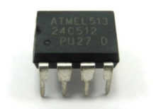
The AT24C512 is a 512-Kbit Electrically Erasable Programmable Read-Only Memory (EEPROM) organized as 65,536 words of 8 bits each. It is a high-density memory device used in a wide range of applications including industrial, automotive, and consumer electronics. The AT24C512 uses an I²C interface for communication, making it easy to integrate into various systems.
Key Features:
- Memory Size: 512 Kbits (64 KB)
- Organization: 65,536 x 8
- Interface: I²C (Inter-Integrated Circuit)
- Operating Voltage: 1.7V to 5.5V
- Data Retention: 100 years
- Endurance: 1,000,000 write cycles
- Access Time: 1 ms (byte write)
- Package Types: Available in several packages including 8-lead SOIC, TSSOP, and PDIP
Technical Specifications:
- Memory: 512 Kbits (64 KB)
- Interface: I²C-compatible (two-wire serial interface)
- Clock Frequency: Up to 1 MHz for Fast-mode Plus (FM+)
- Write Protection: Hardware write protection available via WP pin
- Temperature Range: -40°C to 85°C (industrial grade)
- Package Options: 8-lead SOIC, 8-lead TSSOP, 8-lead PDIP
- Dimensions: Varies by package, e.g., SOIC-8: 5.0 mm x 4.0 mm x 1.5 mm (typical)
Applications:
- Consumer Electronics: Used in televisions, remote controls, and gaming consoles.
- Industrial Control: Employed in data logging, sensor calibration, and system configuration storage.
- Automotive: Utilized in engine control units, infotainment systems, and other in-vehicle electronics.
- Medical Devices: Stores calibration data and patient information.
- Networking Equipment: Used in routers, switches, and other network devices for configuration settings.
Datasheet:
For detailed technical information, refer to the AT24C512 EEPROM Datasheet provided by the manufacturer.
|
The Toggle Switch 6A is a reliable and durable electrical switch designed for controlling electrical circuits in various applications. It features a robust toggle mechanism that allows for easy on/off switching. Capable of handling a current rating of up to 6A, this switch is suitable for use in both low and medium power applications. It is commonly used in household appliances, automotive applications, and industrial machinery.
Key Features:
- Rated for 6A current handling
- Durable toggle mechanism for reliable switching
- Can be used for AC and DC applications
- Available in single-pole or double-pole configurations
- Compact and easy to install
- Available with various actuator styles and mounting options
Technical Specifications:
- Current Rating: 6A
- Voltage Rating: Typically up to 250V AC or 28V DC (depends on the specific model)
- Contact Configuration: Single-Pole Single-Throw (SPST) or Double-Pole Double-Throw (DPDT)
- Actuator Type: Toggle
- Mounting Type: Panel mount
- Insulation Resistance: Typically >100 MΩ
- Dielectric Strength: Typically 1500V AC
- Operating Temperature Range: -25°C to +85°C
Applications:
- Household appliances (e.g., fans, ovens)
- Automotive controls (e.g., light switches)
- Industrial machinery (e.g., machine controls)
- DIY electronics projects
- Control panels and dashboards
Usage:
- Mount the toggle switch on a panel or enclosure using the provided mounting hardware or screws.
- Connect the electrical wires to the switch terminals according to the circuit requirements (refer to the switch’s wiring diagram if available).
- Ensure that the switch is properly secured and insulated to avoid accidental contact.
- Test the switch operation to ensure proper functionality and reliability.
Caution:
- Ensure that the switch is rated appropriately for the voltage and current of your application to prevent overheating or damage.
- Avoid using the switch in environments with excessive moisture or dust unless it is specifically rated for such conditions.
- Handle with care to prevent damage to the toggle mechanism or electrical contacts.
Datasheet:
For detailed technical specifications, refer to the Toggle Switch 6A Datasheet.
|
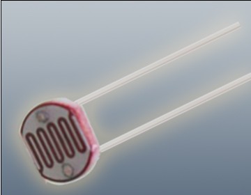
The Photoresistor LDR (Light Dependent Resistor) is a variable resistor whose resistance changes with the light intensity that falls upon it. It is widely used in light sensing applications and projects where detecting light levels is essential. LDRs are cost-effective, easy to use, and suitable for various electronic projects, including light meters, street lights, and other light-sensitive devices.
Key Features:
- Light Sensitivity: Resistance decreases with increasing light intensity
- Simple Interface: Easy to integrate with microcontrollers and analog circuits
- Low Cost: Economical solution for light detection
- Wide Range of Light Detection: Can detect various light levels from low to high intensity
- Compact Size: Fits easily into small projects
Technical Specifications:
- Resistance in Darkness: Typically 1MΩ (depending on specific model)
- Resistance in Bright Light: Typically 10-20kΩ (depending on specific model)
- Spectral Peak: Approximately 540nm (most sensitive to green light)
- Response Time: Rise time ~20ms, fall time ~30ms
- Operating Temperature Range: -30°C to +70°C
- Diameter: Typically 5mm to 10mm (depending on specific model)
Applications:
- Light Meters: Measure light intensity for photography and scientific applications.
- Street Lights: Automatic on/off control based on ambient light levels.
- Alarm Systems: Detect changes in light levels for security purposes.
- Consumer Electronics: Light-sensitive control in devices like clocks and displays.
- Educational Projects: Common component in learning modules for electronics.
Usage:
- Circuit Integration: Connect the LDR in a voltage divider circuit with a fixed resistor to create a variable voltage output based on light intensity.
- Microcontroller Interface: Read the voltage output from the LDR circuit using an analog input pin on a microcontroller.
- Programming: Write code to interpret the analog signal and perform actions based on light levels (e.g., turning on an LED when it gets dark).
- Testing: Calibrate the LDR circuit for the desired light sensitivity by adjusting the fixed resistor value.
Caution:
- Environment: Avoid exposure to extreme temperatures and humidity, which may affect the LDR’s performance.
- Handling: Handle with care to avoid damaging the sensitive surface of the LDR.
Datasheet:
For detailed technical specifications, refer to the Photoresistor LDR Datasheet.
|
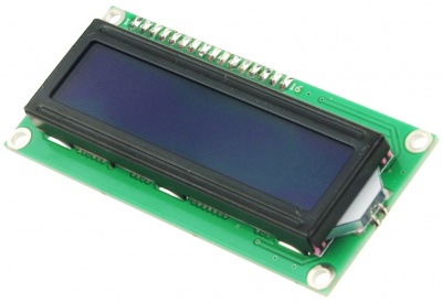
The Blue LCD 1602 is a 16×2 character liquid crystal display module with a blue backlight and white characters. It is widely used in electronic projects for displaying text and simple graphics. This module is compatible with various microcontrollers and development boards, making it a popular choice for embedded systems and DIY projects. The LCD 1602 provides a clear and bright display, ensuring easy readability in different lighting conditions.
Key Features:
- Display: 16 characters x 2 lines
- Backlight: Blue backlight with white characters
- Interface: Parallel interface (8-bit or 4-bit mode)
- Controller: HD44780 compatible
- Adjustable Contrast: Potentiometer control for contrast adjustment
- Operating Voltage: 5V
- Compact Size: Easy to integrate into various projects
- Low Power Consumption: Efficient power usage
Technical Specifications:
- Display Size: 16×2 characters
- Backlight Color: Blue
- Character Color: White
- Controller Type: HD44780 or compatible
- Interface: Parallel (4-bit or 8-bit mode)
- Operating Voltage: 5V
- Current Consumption: Typically 2mA (without backlight), 25mA (with backlight)
- Character Size: 5.56mm x 2.96mm
- Module Size: 80mm x 36mm x 12mm
- Operating Temperature Range: -20°C to +70°C
Applications:
- Embedded Systems: Display information in microcontroller-based projects.
- DIY Projects: Ideal for hobbyists and makers for various projects.
- Consumer Electronics: Used in appliances and gadgets for information display.
- Instrumentation: Display readings and data in measurement and control systems.
- Educational Projects: Commonly used in educational kits and learning modules.
Usage:
- Wiring: Connect the LCD module to a microcontroller or development board using the parallel interface.
- Programming: Use libraries (e.g., LiquidCrystal for Arduino) to control the display and send text/commands.
- Contrast Adjustment: Use the potentiometer to adjust the contrast for optimal visibility.
- Integration: Incorporate the LCD into your project to display relevant information.
Caution:
- Voltage Levels: Ensure the operating voltage is maintained at 5V to prevent damage.
- Proper Handling: Handle with care to avoid damaging the delicate LCD screen.
Datasheet:
For detailed technical specifications, refer to the Blue LCD 1602 Datasheet.
|
|
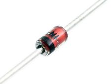
The 1N4733A is a Zener diode designed to provide a stable reference voltage of 5.1V with a power dissipation capability of 1W. This Zener diode is suitable for applications requiring accurate voltage regulation, voltage referencing, and protection against overvoltage conditions. It offers reliable performance for general-purpose circuits.
Key Features:
- Nominal Zener Voltage: 5.1V
- Power Dissipation: 1W
- Tight tolerance for precise voltage regulation
- Low leakage current
- High stability and reliability
- Axial-leaded design for easy PCB mounting
Technical Specifications:
- Zener Voltage (Vz): 5.1V
- Test Current (Iz): 49mA
- Maximum Zener Impedance (Zz): 2 ohms at Iz
- Maximum Reverse Leakage Current (Ir): 5µA at Vr = 1V
- Power Dissipation (Pd): 1W
- Operating Temperature Range: -65°C to +200°C
- Package Type: DO-41 (Axial)
- Dimensions: Length: 4.5mm, Diameter: 2.0mm (approx.)
Applications:
- Voltage Regulation: Provides a stable reference voltage for various circuits.
- Overvoltage Protection: Protects sensitive electronic components from voltage spikes.
- Voltage Clamping: Limits the voltage to a specific value to protect circuits.
- Signal Conditioning: Used in waveform clipping and shaping circuits.
- Reference Voltage: Provides a precise reference voltage in measurement and control systems.
Usage:
- Identify the correct placement for the Zener diode in your circuit based on the schematic.
- Ensure the Zener diode’s voltage and power rating match the circuit’s requirements.
- Solder the Zener diode into place, observing proper polarity (cathode marked with a band).
- Test the circuit to verify the Zener diode is functioning as expected.
Caution:
- Ensure the Zener diode’s power rating is not exceeded to prevent overheating and failure.
- Handle with care to avoid damaging the diode during installation.
- Verify the Zener diode’s specifications match the requirements of your application.
Datasheet:
For detailed technical specifications, refer to the 1N4733A Zener Diode Datasheet.
|
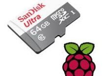
The Raspberry Pi SD Card 64GB is a high-capacity microSD card designed to provide ample storage for your Raspberry Pi projects. This microSD card offers a significant amount of space for operating systems, applications, data, and multimedia files, ensuring smooth and efficient performance. It is ideal for more complex and storage-intensive projects using any Raspberry Pi model with a microSD card slot.
Key Features:
- 64GB storage capacity
- Pre-loaded with the Raspberry Pi operating system (optional)
- High-speed data transfer rates
- Reliable and durable design
- Compatible with all Raspberry Pi models with a microSD card slot
- Ideal for projects requiring substantial storage space
- Easy to set up and use
Technical Specifications:
- Capacity: 64GB
- Format: MicroSDXC
- Speed Class: Class 10, UHS-I or UHS-II (varies by model)
- Read Speed: Up to 100MB/s (varies by model)
- Write Speed: Up to 90MB/s (varies by model)
- Operating Voltage: 2.7V to 3.6V
- Operating Temperature: -25°C to +85°C
- Storage Temperature: -40°C to +85°C
- Dimensions: Standard microSD card size
Applications:
- Raspberry Pi OS and application storage
- Data logging and storage
- Multimedia projects
- IoT applications
- Education and development projects
- Complex software development and testing
Datasheet:
For detailed technical information, please refer to the MicroSD Card Datasheet.
|
