|
Description |
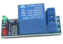
The Relay Module 1 Channel is a versatile electronic switch that allows you to control high voltage, high current loads with low voltage signals. This module is ideal for interfacing microcontrollers with electrical appliances, motors, lights, and other devices. It features an optocoupler for improved isolation and protection.
Key Features:
- 1-channel relay with optocoupler isolation
- Control high voltage devices with low voltage signals
- Compatible with various microcontroller platforms (e.g., Arduino, Raspberry Pi)
- LED indicator for relay status
- Compact design for easy integration
Technical Specifications:
- Relay Type: SPDT (Single Pole Double Throw)
- Operating Voltage: 5V DC
- Trigger Voltage: 3.3V to 5V DC
- Control Signal: Low-level trigger (active low)
- Max Switching Voltage: 250V AC / 30V DC
- Max Switching Current: 10A
- Optocoupler Isolation: Yes
- Dimensions: Approximately 50mm x 26mm x 18mm
Applications:
- Home automation systems
- Industrial control
- Robotics
- Smart appliances
- Remote control of devices
- Automation projects
Usage:
- Connection:
- Connect the VCC and GND pins to the 5V and GND of the microcontroller.
- Connect the IN pin to a digital output pin of the microcontroller to control the relay.
- Connect the relay output terminals (COM, NO, and NC) to the load as per the required switching configuration.
- Programming:
- Write code to control the relay using the digital output pin, setting it HIGH or LOW to turn the relay on or off.
- Use libraries or direct pin control methods as appropriate for your microcontroller platform.
- Testing:
- Verify the relay operation by toggling the control pin and observing the LED indicator and the switching of the connected load.
Caution:
- Ensure proper insulation and safety measures when handling high voltage circuits.
- Verify the load specifications and ensure they are within the relay’s rated capacity.
- Handle the module carefully to avoid damage to the relay and the optocoupler.
Datasheet:
For detailed technical specifications, refer to the Relay Module 1 Channel Datasheet.
|
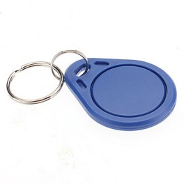
The 125KHZ RFID Key Chain is a compact and durable radio-frequency identification (RFID) device used for access control and identification applications. It operates at a frequency of 125kHz and is compatible with standard RFID readers. The key chain format makes it convenient to carry and use for various applications such as security systems, attendance tracking, and asset management.
Key Features:
- Operates at 125kHz frequency
- Durable and compact key chain design
- Compatible with standard RFID readers
- Unique identification number (UID) for each key chain
- Waterproof and shock-resistant
- Long read range (up to 10 cm depending on the reader)
- No battery required (passive RFID technology)
Technical Specifications:
- Operating Frequency: 125kHz
- Material: ABS plastic
- Dimensions: Approximately 40mm x 32mm x 4mm
- Weight: Approximately 6g
- Read Range: Up to 10 cm (depending on the reader and environment)
- Data Storage: 64-bit read-only unique identifier (UID)
- Operating Temperature Range: -25°C to +85°C
- Color: Typically blue, but may vary by manufacturer
- Waterproof: Yes
Applications:
- Access control systems
- Time and attendance tracking
- Membership management
- Asset tracking
- Secure entry systems
- Contactless payment systems
Usage:
- Integration:
- Enroll the RFID key chain in the desired RFID system by registering its unique identifier (UID) with the system’s database.
- Operation:
- Present the key chain to an RFID reader within the read range (up to 10 cm).
- The reader will capture the UID and communicate it to the control system for processing.
- Security:
- Use the key chain for secure access to restricted areas or for tracking attendance.
- Pair the key chain with a compatible RFID reader and control system for seamless operation.
Caution:
- Avoid exposing the key chain to extreme temperatures or harsh chemicals.
- Do not bend or apply excessive force to the key chain to prevent damage.
- Keep the key chain away from strong magnetic fields to ensure proper operation.
Datasheet:
For detailed technical specifications, refer to the manufacturer’s datasheet for your specific 125kHz RFID key chain model.
|
The Wemos D1 WiFi UNO is a microcontroller development board that combines the features of the popular Arduino UNO with built-in WiFi capabilities, thanks to the integration of the ESP8266 module. It is designed for IoT (Internet of Things) applications, enabling easy connection to WiFi networks and interaction with cloud services or other devices over the internet.
Key Features:
- Compatible with Arduino IDE for ease of development
- Built-in WiFi connectivity via ESP8266 module
- Microcontroller based on the ESP8266 chip
- USB interface for programming and power
- 11 digital I/O pins, including 1 PWM output
- 1 analog input
- Onboard LED and reset button
- Compact design suitable for various applications
Technical Specifications:
- Microcontroller: ESP8266
- Operating Voltage: 3.3V DC
- WiFi Connectivity: 802.11 b/g/n
- Digital I/O Pins: 11
- PWM Outputs: 1
- Analog Input: 1 (0-1V range)
- Flash Memory: 4 MB (typically)
- Clock Speed: 80 MHz or 160 MHz
- Package Type: Standard Arduino UNO layout
- Dimensions: Approximately 68mm x 53mm
Applications:
- Internet of Things (IoT) projects
- Home automation systems
- Wireless data logging
- Remote sensor monitoring
- Smart home devices
- Educational projects in electronics and programming
Usage:
- Connect the Wemos D1 WiFi UNO to your computer via the USB interface.
- Install the necessary drivers and Arduino IDE with the ESP8266 board support package.
- Write and upload your code using the Arduino IDE, leveraging the WiFi capabilities to connect to networks or web services.
- Use the digital I/O pins, analog input, and onboard LED in your projects according to your needs.
- Monitor and debug your project using serial output or other communication methods.
Caution:
- Ensure proper USB connection and avoid overvoltage to prevent damage.
- Follow the WiFi module’s usage guidelines for optimal performance and connectivity.
- Handle with care to avoid damage to the onboard components.
Datasheet:
For detailed technical specifications, refer to the Wemos D1 WiFi UNO Datasheet.
|
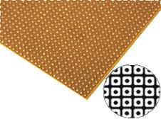
A small size dotted Vero board, also known as a stripboard or prototyping board, is a type of circuit board that is used for prototyping and building electronic circuits. It features a grid of holes with copper pads that allow components to be easily soldered onto the board. The dotted pattern provides flexibility in layout, making it ideal for custom circuit designs and small electronic projects.
Key Features:
- Dotted pattern for versatile circuit layout
- High-quality FR4 material for durability
- Copper pads for easy soldering
- Small size for compact projects
- Compatible with through-hole components
- Suitable for prototyping and custom circuit building
Technical Specifications:
- Material: FR4 (fiberglass epoxy laminate)
- Size: Typically around 70mm x 90mm (varies by manufacturer)
- Hole Pitch: 2.54mm (standard 0.1 inch grid)
- Hole Diameter: 1.0mm (suitable for most through-hole components)
- Thickness: 1.6mm
- Copper Thickness: 35µm (1oz/ft²)
- Pattern: Dotted (individual copper pads)
- Number of Holes: Varies by board size (e.g., 25×35 grid for 70mm x 90mm board)
Applications:
- Prototyping electronic circuits
- Custom circuit design
- DIY electronics projects
- Educational and learning purposes
- Small-scale production of custom circuits
Usage:
- Design the Circuit:
- Plan the layout of your components and connections on the Vero board.
- Place the Components:
- Insert the components into the holes according to your circuit design.
- Solder the Components:
- Solder the component leads to the copper pads on the reverse side of the board.
- Create Connections:
- Use solder bridges or wire links to create electrical connections between the copper pads as needed.
- Test the Circuit:
- Verify the circuit functionality and make any necessary adjustments or corrections.
Caution:
- Ensure proper soldering techniques to avoid short circuits or poor connections.
- Handle the board carefully to avoid damaging the copper pads or FR4 material.
- Verify the component placement and connections before powering the circuit.
|
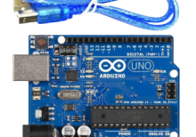
The Arduino Uno R3 is a popular microcontroller board based on the ATmega328P. It is designed for easy integration into a wide range of applications, from hobby projects to professional prototyping. The board features a comprehensive set of I/O pins, communication interfaces, and power options, making it ideal for learning, experimentation, and development of embedded systems.
Key Features:
- Microcontroller: ATmega328P
- 14 Digital I/O Pins (6 PWM outputs)
- 6 Analog Input Pins
- Clock Speed: 16 MHz
- USB connection for programming and power
- 32KB Flash Memory (0.5KB used by bootloader)
- 2KB SRAM and 1KB EEPROM
- Built-in Power LED
- Supports SPI, I2C, and UART communication
Technical Specifications:
- Microcontroller: ATmega328P
- Operating Voltage: 5V
- Input Voltage (recommended): 7-12V
- Input Voltage (limits): 6-20V
- Digital I/O Pins: 14 (of which 6 provide PWM output)
- Analog Input Pins: 6
- DC Current per I/O Pin: 20 mA
- DC Current for 3.3V Pin: 50 mA
- Flash Memory: 32 KB (ATmega328P) of which 0.5 KB used by bootloader
- SRAM: 2 KB (ATmega328P)
- EEPROM: 1 KB (ATmega328P)
- Clock Speed: 16 MHz
- USB Connector: Type B
- Dimensions: 68.6 mm x 53.4 mm
- Weight: 25 g
Applications:
- Embedded system prototyping
- DIY electronics projects
- Educational tools for learning programming and electronics
- Robotics
- IoT (Internet of Things) devices
- Automation and control systems
Usage:
- Programming:
- Connect the Arduino Uno R3 to your computer using a USB cable.
- Open the Arduino IDE and select the board and correct COM port.
- Write your program (sketch) and upload it to the board.
- Powering:
- The board can be powered via the USB connection or with an external power supply (7-12V recommended).
- External power can be supplied through the power jack or via the Vin pin.
- Interfacing:
- Use the digital and analog I/O pins to connect sensors, actuators, and other components.
- Utilize communication interfaces like SPI, I2C, and UART for connecting to other devices and modules.
Caution:
- Avoid exceeding the maximum current ratings to prevent damage to the board.
- Ensure proper handling to avoid static discharge which can damage the microcontroller.
- Use a proper power supply to avoid over-voltage damage.
Datasheet:
For detailed technical specifications, refer to the Arduino Uno R3 Datasheet.
|
The Arduino Pro Mini is a compact, versatile microcontroller board based on the ATmega328P. Designed for advanced users who require a small form factor and flexibility, it is ideal for embedded systems, wearable projects, and space-constrained applications. The Pro Mini provides all the functionality of the Arduino Uno with reduced size and power consumption.
Key Features:
- ATmega328P microcontroller
- Compact and lightweight design
- 14 digital I/O pins (6 can be used as PWM outputs)
- 8 analog input pins
- On-board reset button
- Operating voltage: 5V
- Clock speed: 16 MHz
- Low power consumption
Technical Specifications:
- Microcontroller: ATmega328P
- Operating Voltage: 5V
- Input Voltage: 5-12V
- Digital I/O Pins: 14 (of which 6 provide PWM output)
- Analog Input Pins: 8
- DC Current per I/O Pin: 40 mA
- Flash Memory: 32 KB (of which 2 KB used by bootloader)
- SRAM: 2 KB
- EEPROM: 1 KB
- Clock Speed: 16 MHz
- Dimensions: 18mm x 33mm
Applications:
- Embedded systems
- Wearable technology
- Robotics
- DIY electronics projects
- Prototyping and development
- Educational tools
Usage:
- Connect the Arduino Pro Mini to a USB-to-serial adapter for programming.
- Install the Arduino IDE and configure it for the Pro Mini.
- Write, compile, and upload your code to the Pro Mini.
- Integrate the Pro Mini into your project, connecting sensors, actuators, and other peripherals as needed.
- Power the Pro Mini using an external power source within the specified voltage range.
Caution:
- Ensure correct voltage levels to prevent damage to the board.
- Handle with care to avoid static discharge.
- Verify all connections and components before powering the board.
Datasheet:
For detailed technical specifications, refer to the Arduino Pro Mini Datasheet.
|
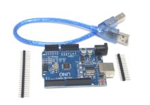
- The Arduino UNO R3 SMD is a popular and versatile microcontroller board based on the ATmega328P microcontroller. The SMD (Surface-Mount Device) version features the ATmega328P microcontroller in an SMD package, offering the same functionality as the traditional UNO R3 but with a more compact design. It is widely used for a variety of projects, from simple experiments to complex prototypes.
Key Features:
- Microcontroller: ATmega328P in SMD package
- Operating Voltage: 5V
- Input Voltage (recommended): 7-12V
- Digital I/O Pins: 14 (of which 6 provide PWM output)
- Analog Input Pins: 6
- Flash Memory: 32 KB (ATmega328P) of which 0.5 KB used by bootloader
- SRAM: 2 KB (ATmega328P)
- EEPROM: 1 KB (ATmega328P)
- Clock Speed: 16 MHz
- USB Connection: Standard USB-B for programming and communication
- Power Jack: 2.1mm center-positive barrel jack
- ICSP Header: For in-circuit programming
- Reset Button: For easy reset of the microcontroller
Technical Specifications:
- Microcontroller: ATmega328P
- Operating Voltage: 5V
- Input Voltage (limits): 6-20V
- Digital I/O Pins: 14 (6 PWM)
- PWM Digital I/O Pins: 6
- Analog Input Pins: 6
- DC Current per I/O Pin: 20 mA
- DC Current for 3.3V Pin: 50 mA
- Flash Memory: 32 KB (ATmega328P) of which 0.5 KB used by bootloader
- SRAM: 2 KB (ATmega328P)
- EEPROM: 1 KB (ATmega328P)
- Clock Speed: 16 MHz
- Length: 68.6 mm
- Width: 53.4 mm
- Weight: 25 g
Applications:
- Educational Projects: Ideal for beginners and students learning electronics and programming.
- Prototyping: Widely used for developing and testing new electronic devices and systems.
- Robotics: Can be used as a controller for various robotics projects.
- Home Automation: Suitable for creating smart home devices and automation systems.
- DIY Projects: Perfect for hobbyists and makers building custom gadgets and interactive installations.
Datasheet:
For detailed technical specifications, refer to the Arduino UNO R3 SMD Datasheet.
|
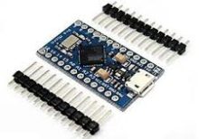
The Arduino Pro Micro is a compact and versatile microcontroller board based on the ATmega32U4 microchip. It is part of the Arduino family and designed for projects where space is limited. The Pro Micro board features built-in USB capabilities, allowing it to emulate a keyboard, mouse, or other USB devices, making it suitable for a wide range of applications including custom input devices and embedded systems.
Key Features:
- Microcontroller: ATmega32U4
- Operating Voltage: 5V
- Input Voltage (recommended): 7-12V
- Digital I/O Pins: 18
- Analog Input Pins: 9
- Flash Memory: 32 KB (ATmega32U4), of which 4 KB used by bootloader
- SRAM: 2.5 KB
- EEPROM: 1 KB
- Clock Speed: 16 MHz
- USB: Built-in USB functionality for direct connection to computers and emulation of USB devices
Technical Specifications:
- Dimensions: 33 mm x 18 mm
- Weight: Approximately 8 g
- Communication: UART, SPI, I2C, USB
- On-board LEDs: TX, RX, Power, and one user-defined LED
- Power:
- DC Current per I/O Pin: 40 mA
- DC Current for 3.3V Pin: 50 mA
- Connectors:
- USB Micro-B for programming and power
- 6-pin header for serial communication
- Pins for additional communication interfaces and power
Applications:
- Custom Input Devices: Can be used to create custom keyboards, mice, and other input devices.
- Embedded Systems: Suitable for small-scale embedded projects where USB connectivity is required.
- Prototyping: Ideal for rapid prototyping and development due to its compact size and USB capability.
- IoT Projects: Can be integrated into Internet of Things (IoT) devices for various control and monitoring applications.
- Wearables: Perfect for wearable electronics and projects requiring a small form factor.
Datasheet:
For detailed technical information, refer to the Arduino Pro Micro Datasheet.
|
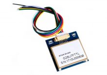
The VK2828 G28U7FTTL is a high-performance GPS module designed for aviation and other high-precision applications. It features a wide range of operational frequencies and is capable of delivering accurate positional data for navigation and tracking purposes. The module is ideal for integration into systems requiring reliable and precise GPS information.
Key Features:
- High Update Rate: Capable of updating position data from 1Hz to 10Hz, allowing for smooth and accurate tracking
- Sensitivity: Designed for use in aviation, providing robust performance in various environmental conditions
- Compatibility: Supports standard GPS protocols for easy integration into existing systems
- Compact Size: Suitable for integration into space-constrained applications
Technical Specifications:
- Type: GPS Module
- Model: VK2828 G28U7FTTL
- Update Rate: 1Hz to 10Hz
- Frequency Range: Supports standard GPS frequencies
- Sensitivity: High sensitivity for accurate positioning
- Protocol: NMEA-0183
- Operating Voltage: Typically 3.3V to 5V DC
- Power Consumption: Low power consumption for battery-operated applications
- Dimensions: Varies by model, generally compact for easy integration
- Antenna: May include an external or integrated antenna depending on the model
Applications:
- Aviation: Navigation and tracking for aircraft
- Marine: Boat and ship navigation
- Automotive: Advanced driver-assistance systems (ADAS)
- Outdoor Activities: Hiking and sports tracking
- Industrial: Asset tracking and fleet management
Usage:
- Powering the Module: Connect the GPS module to a suitable power source within the specified voltage range.
- Connecting the Antenna: Ensure the antenna is properly connected and positioned for optimal signal reception.
- Data Integration: Use the NMEA protocol to receive GPS data, including latitude, longitude, altitude, and time.
- Integration: Connect the GPS module to your system or application for real-time tracking and navigation.
Caution:
- Signal Reception: Ensure the module has a clear view of the sky for optimal GPS signal reception.
- Voltage: Verify the operating voltage to avoid damage to the module.
- Antenna Placement: Position the antenna to minimize interference and maximize signal strength.
Datasheet:
For detailed technical specifications, refer to the VK2828 G28U7FTTL Datasheet .
|
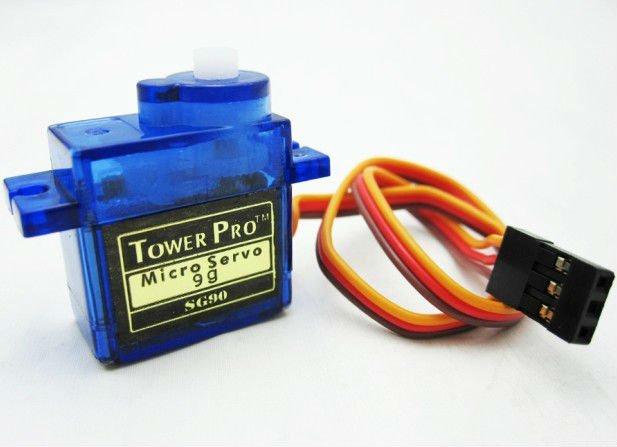
The SG90 is a popular micro servo motor known for its small size, lightweight, and reliable performance. It is ideal for use in RC applications, robotics, and other hobbyist and DIY projects. The servo provides precise control over angular position, speed, and acceleration.
Key Features:
- Lightweight and compact design
- High precision and stable movement
- Nylon gears for smooth operation
- Compatible with most radio control systems
- Easy to interface with microcontrollers
- Includes various servo horns and mounting hardware
Technical Specifications:
- Operating Voltage: 4.8V to 6.0V
- Stall Torque: 1.8 kg/cm (4.8V), 2.2 kg/cm (6.0V)
- Speed: 0.12 sec/60° (4.8V), 0.10 sec/60° (6.0V)
- Rotation Angle: 0° to 180°
- Control System: PWM (Pulse Width Modulation)
- Gear Type: Nylon
- Connector Wire Length: 250mm
- Dimensions: 23mm x 12.2mm x 29mm
- Weight: 9g
Applications:
- RC vehicles (cars, airplanes, boats)
- Robotics
- Mechanical arms and grippers
- Pan/tilt mechanisms for cameras and sensors
- DIY electronics projects
- Animatronics
Usage:
- Connection:
- Connect the VCC (red) wire to a 5V power supply.
- Connect the GND (brown) wire to ground.
- Connect the signal (orange) wire to a PWM output on the microcontroller or servo controller.
- Control:
- Use PWM signals to control the angular position of the servo.
- Adjust the pulse width (typically between 1ms and 2ms) to move the servo to the desired position.
- Mounting:
- Use the included servo horns and mounting hardware to attach the servo to your project.
- Ensure the servo is securely mounted to handle the torque generated during operation.
Caution:
- Avoid stalling the servo for extended periods to prevent overheating.
- Ensure the servo operates within the specified voltage range to avoid damage.
- Handle the servo carefully to prevent damage to the internal gears and motor.
Datasheet:
For detailed technical specifications, refer to the SG90 Servo Datasheet.
|
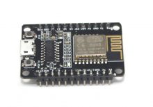
The ESP8285 ESP-M2 NodeMCU WiFi Development Board is a compact and versatile development board based on the ESP8285 chipset. It integrates Wi-Fi connectivity, making it ideal for IoT (Internet of Things) projects requiring wireless communication capabilities. This board is compatible with the NodeMCU firmware and development environment, offering ease of use and rapid prototyping for IoT applications.
Key Features:
- ESP8285 Chipset: Integrates Wi-Fi connectivity for IoT applications.
- NodeMCU Compatible: Supports NodeMCU firmware and development environment.
- USB-to-Serial Converter: Includes an onboard USB-to-Serial converter (CH340 or CP2102) for easy programming and debugging.
- Expansion Headers: Provides GPIO pins for connecting sensors, actuators, and other peripherals.
- Micro USB Port: Allows for power supply and programming via USB connection.
- Reset and Flash Buttons: Onboard buttons for reset and flashing firmware.
- Integrated Antenna: Built-in antenna for wireless communication.
Technical Specifications:
- Microcontroller: ESP8285 (based on ESP8266)
- Wi-Fi Standard: IEEE 802.11 b/g/n
- Operating Voltage: 3.3V DC
- Digital I/O Pins: GPIO, SPI, I2C, UART
- Analog Input Pins: 1 (10-bit ADC)
- USB Interface: Micro USB for power and programming
- Flash Memory: 1MB (expandable via SPI flash)
- Operating Temperature Range: -40°C to +125°C
- Dimensions: Typically around 48mm x 26mm
Applications:
- IoT Projects: Home automation, smart devices, sensor networks.
- Wireless Communication: Remote monitoring, data logging, telemetry.
- Prototyping: Rapid development of Wi-Fi enabled applications.
- Educational Use: Learning and experimenting with IoT technologies.
- Embedded Systems: Integration into various embedded systems and devices.
Datasheet:
For detailed technical specifications, refer to the ESP8285 ESP-M2 NodeMCU WiFi Development Board Datasheet .
|
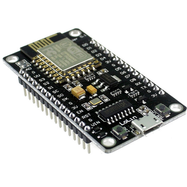
The ESP8266 NodeMcu LUA WiFi Development Board is an open-source IoT platform. It integrates the ESP8266 WiFi module, which allows for easy development of WiFi-based applications. The board includes the Lua scripting language for programming, enabling quick and efficient development. This development board is highly suitable for beginners and professionals looking to build IoT projects due to its simplicity, low cost, and robust capabilities.
Key Features:
- WiFi Module: Integrated ESP8266 with full TCP/IP stack and microcontroller capability
- Programming Language: Lua scripting language support
- GPIO: Multiple GPIO pins available for connecting sensors and actuators
- USB Interface: On-board USB to serial interface for easy programming
- Memory: 4MB Flash Memory
- Power Supply: Can be powered via micro USB or external power supply
- Built-in Antenna: On-board WiFi antenna for wireless connectivity
- Compact Size: Small form factor for easy integration into projects
Technical Specifications:
- Dimensions: 48 mm x 26 mm
- Weight: Approximately 10 g
- Operating Voltage: 3.3V
- Digital I/O Pins: 11
- Analog Input Pins: 1 (max input 3.2V)
- Clock Speed: 80 MHz
- Flash Memory: 4MB
- USB to UART: CP2102 or CH340G
- Power Consumption:
- Deep Sleep: <10 μA
- Light Sleep: <1 mA
- Modem Sleep: ~15 mA
- Active Mode: ~70 mA
- WiFi Standards: 802.11 b/g/n
- Connector Types: Micro USB, GPIO headers
Applications:
- IoT Projects: Ideal for developing Internet of Things applications with WiFi connectivity.
- Home Automation: Control and monitor home appliances and systems remotely.
- Prototyping: Rapid development and testing of WiFi-enabled prototypes.
- Wireless Sensor Networks: Creating networks of sensors with real-time data collection and communication.
- Smart Devices: Integrating WiFi capabilities into various smart devices and gadgets.
Datasheet:
For detailed technical information, refer to the ESP8266 NodeMcu LUA WiFi Development Board Datasheet.
|
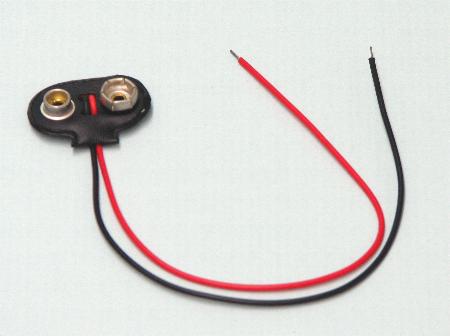
The 9V Battery Connector is a convenient and reliable accessory used to connect 9V batteries to electronic circuits and devices. It features a pair of snap connectors that securely attach to the terminals of a 9V battery, providing an easy way to power various projects and components.
Key Features:
- Easy and secure connection to 9V batteries
- Color-coded wires for correct polarity
- Flexible and durable leads for reliable connections
- Compatible with various electronic projects and devices
- Lightweight and compact design
Technical Specifications:
- Connector Type: Snap-on for 9V battery
- Wire Length: Typically around 15cm (varies by manufacturer)
- Wire Gauge: 24 AWG (varies by manufacturer)
- Polarity: Red wire for positive (+), black wire for negative (-)
- Material: Plastic housing with metal contacts
- Rated Voltage: 9V
- Current Capacity: Up to 1A
Applications:
- Powering small electronic projects
- Battery-powered devices
- Portable electronics
- Prototyping and breadboarding
- DIY and hobby projects
Usage:
- Connection:
- Snap the connector onto the terminals of a 9V battery, ensuring correct polarity (red wire to positive, black wire to negative).
- Wiring:
- Connect the leads to your circuit or device, observing proper polarity.
- Use solder, connectors, or a breadboard to make secure connections.
- Powering Devices:
- Use the 9V battery and connector to power your electronic projects, ensuring the voltage and current requirements are compatible.
Caution:
- Ensure correct polarity to avoid damaging the battery or connected device.
- Handle the connector and wires carefully to prevent short circuits.
- Avoid excessive bending or pulling on the wires to maintain reliable connections.
|
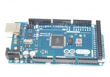
The Arduino Mega 2560 is a popular microcontroller board based on the ATmega2560 chip, offering a substantial increase in input/output (I/O) pins, memory, and functionality compared to other Arduino boards. It is designed for projects requiring a large number of I/O pins or more complex operations, making it suitable for advanced hobbyist and professional applications.
Key Features:
- ATmega2560 Microcontroller
- 256KB Flash memory for storing code
- 8KB SRAM for data storage
- 4KB EEPROM for non-volatile data storage
- 54 Digital I/O pins (15 with PWM output)
- 16 Analog input pins
- 4 Hardware serial ports (UARTs)
- 16 MHz Clock speed
- USB connection for programming and power
- Power jack for external power supply
- Built-in LED on pin 13
Technical Specifications:
- Microcontroller: ATmega2560
- Operating Voltage: 5V
- Input Voltage (recommended): 7-12V
- Input Voltage (limit): 6-20V
- Digital I/O Pins: 54 (15 with PWM)
- Analog Input Pins: 16
- Flash Memory: 256 KB (of which 8 KB used by bootloader)
- SRAM: 8 KB
- EEPROM: 4 KB
- Clock Speed: 16 MHz
- Dimensions: 101.6 mm x 53.3 mm (4 in x 2.1 in)
- Weight: Approximately 37 g (1.3 oz)
Applications:
- Robotics: Control motors, sensors, and other peripherals for robotic systems
- Home Automation: Interface with various sensors and actuators for smart home projects
- Data Logging: Collect and store data from multiple sensors for analysis
- Prototyping: Develop and test complex electronic circuits and systems
- Educational Projects: Use in educational environments to teach microcontroller programming and electronics
Usage:
- Connect the Arduino Mega 2560 to your computer via USB for programming.
- Use the Arduino IDE to write and upload code to the board.
- Interface with external hardware using the I/O pins for various applications.
- Power the board using either the USB connection or an external power supply.
Caution:
- Ensure the input voltage does not exceed the recommended range to avoid damaging the board.
- Verify connections to avoid incorrect wiring or short circuits.
- Handle with care to prevent damage to the board or its components.
Datasheet:
For detailed technical specifications, refer to the Arduino Mega 2560 Datasheet.
|
The Raspberry Pi Zero W is a compact, low-cost single-board computer that includes built-in Wi-Fi and Bluetooth connectivity. It is designed for a wide range of applications, including embedded projects, IoT devices, and educational tools. The Raspberry Pi Zero W is highly valued for its small form factor and powerful performance relative to its size.
Key Features:
- Processor: 1GHz single-core ARM11 CPU
- Memory: 512MB RAM
- Wireless Connectivity: 802.11 b/g/n Wi-Fi, Bluetooth 4.1, Bluetooth Low Energy (BLE)
- Ports:
- Mini HDMI port for video output
- Micro USB OTG port for data and power
- Micro USB power port
- CSI camera connector
- GPIO: 40-pin GPIO header (unpopulated)
- Storage: MicroSD card slot for operating system and data storage
Technical Specifications:
- Processor: Broadcom BCM2835, 1GHz single-core ARM11
- Memory: 512MB LPDDR2 SDRAM
- Wireless Connectivity:
- 802.11 b/g/n Wi-Fi
- Bluetooth 4.1
- Bluetooth Low Energy (BLE)
- Video Output: Mini HDMI with 1080p60 support
- Audio Output: Via HDMI or I2S
- USB Ports:
- 1 x Micro USB OTG port
- 1 x Micro USB power port
- Camera Interface: CSI camera connector
- GPIO: 40-pin header with various functions (unpopulated)
- Storage: MicroSD card slot
- Dimensions: 65mm x 30mm x 5mm
- Power: 5V, 1.2A via Micro USB
Applications:
- Embedded Projects: Ideal for embedding into custom electronic devices due to its small size and wireless capabilities.
- IoT Devices: Suitable for Internet of Things (IoT) applications needing Wi-Fi and Bluetooth connectivity.
- Education: Used in educational environments to teach programming, electronics, and computer science.
- DIY Projects: Perfect for hobbyists creating custom gadgets, robots, and other interactive installations.
- Media Centers: Can be used to create low-cost media centers or streaming devices.
Datasheet:
For detailed technical information, refer to the official Raspberry Pi Zero W datasheet and documentation.
|
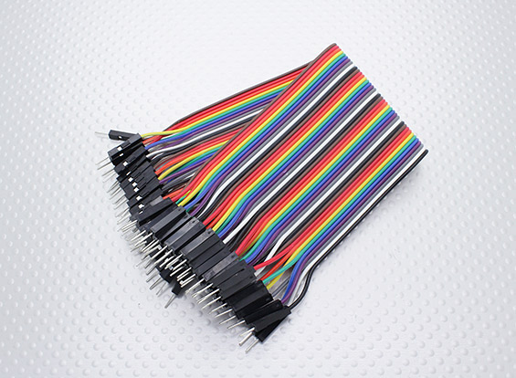
The Male-Male Jumper Wires (Set) is an essential component for breadboarding and prototyping in electronics projects. These wires are used to establish quick and reliable connections between various points in a circuit, such as between the pins of a microcontroller, sensors, modules, and other components. The set typically includes a variety of lengths and colors to help with organizing and identifying connections.
Key Features:
- Easy and quick connections for breadboards and other prototyping environments
- Variety of lengths and colors for flexibility and organization
- Durable and reusable
- Compatible with standard 0.1” (2.54mm) pitch headers
- Ideal for Arduino, Raspberry Pi, and other microcontroller projects
Technical Specifications:
- Connector Type: Male to Male
- Pin Spacing: 0.1” (2.54mm)
- Wire Lengths: Varies (typically 10cm, 20cm, and 30cm)
- Wire Gauge: 24 AWG
- Insulation Material: PVC
- Conductor Material: Copper or copper-clad aluminum
- Colors: Multiple (e.g., red, blue, green, yellow, black, white)
- Quantity: Typically 40 wires per set (may vary)
Applications:
- Breadboarding and prototyping
- Microcontroller and development board projects
- Interfacing sensors and modules
- Educational and DIY electronics projects
- Connecting components in a temporary setup
Usage:
- Connecting Components:
- Use the jumper wires to connect the pins of different components on a breadboard or between header pins on development boards.
- Ensure firm and secure connections by inserting the male ends into the breadboard or header sockets.
- Organizing Circuits:
- Use different colors to identify various connections and signals, making the circuit easier to debug and understand.
- Select appropriate wire lengths to minimize clutter and ensure neat and organized prototyping.
- Reusability:
- Jumper wires can be reused in multiple projects, making them a cost-effective solution for prototyping.
Caution:
- Handle with care to avoid damaging the wire insulation or connectors.
- Ensure correct connections to avoid short circuits or incorrect wiring.
- Store in a dry and cool place to maintain the integrity of the connectors and insulation.
Datasheet:
Refer to the specific manufacturer’s datasheet or product details for more information if available.
|
The STM8S Development Board is a comprehensive platform designed for developing and prototyping with the STM8S series microcontrollers. It provides a robust set of features and peripherals to facilitate a wide range of applications, from simple embedded projects to complex industrial control systems. The board offers easy access to all the microcontroller’s functionalities and includes a variety of interfaces and connectors to enhance development efficiency.
Key Features:
- Microcontroller: Based on the STM8S series microcontroller.
- Peripheral Interfaces: Multiple GPIOs, UART, I2C, SPI, and ADC/DAC interfaces.
- Power Supply Options: Supports multiple power supply options, including USB and external sources.
- On-Board Debugging: Integrated SWIM interface for debugging and programming.
- Expandable: Pin headers for easy expansion with additional modules and shields.
- User-Friendly Design: Includes user LEDs, push buttons, and a reset button for easy development and testing.
- Software Support: Compatible with various IDEs and development tools, including STM8S firmware libraries.
Technical Specifications:
- Microcontroller: STM8S series
- Operating Voltage: 3.3V to 5V
- Communication Interfaces: UART, I2C, SPI
- Analog Inputs: Multiple ADC channels
- Digital I/O: Multiple GPIO pins
- Clock Speed: Up to 16MHz
- Memory: Flash, RAM, and EEPROM (varies by specific STM8S model)
- Dimensions: Compact and portable design
Applications:
- Embedded Systems: Ideal for developing and prototyping embedded systems.
- Industrial Control: Suitable for industrial automation and control applications.
- Education and Training: Perfect for educational purposes and hands-on learning.
- Home Automation: Can be used in home automation projects.
- Consumer Electronics: Applicable in various consumer electronic devices.
Datasheet:
For detailed technical specifications, refer to the STM8S Development Board Datasheet.
|
The Raspberry Pi 5 (8GB RAM) is the latest iteration in the Raspberry Pi series, featuring significant performance improvements and expanded memory to handle more demanding applications. With a powerful quad-core processor, enhanced GPU, and versatile connectivity options, this compact single-board computer is ideal for a wide range of projects and applications.
Key Features:
- 8GB RAM: Ample memory for complex tasks and multitasking
- Quad-Core Processor: Enhanced processing power for improved performance
- Enhanced GPU: Supports 4K video output and better graphics performance
- Multiple Connectivity Options: USB 3.0 ports, Gigabit Ethernet, Bluetooth 5.0, and Wi-Fi
- Expandable Storage: MicroSD card slot and USB boot capability
- GPIO Pins: 40-pin GPIO header for hardware projects
Technical Specifications:
- Processor: Quad-core ARM Cortex-A72, 1.8GHz
- Memory: 8GB LPDDR4 RAM
- Graphics: Broadcom VideoCore VI, supports dual 4K displays
- Storage: MicroSD card slot, USB boot support
- Connectivity:
- 2 x USB 3.0 ports
- 2 x USB 2.0 ports
- Gigabit Ethernet
- Dual-band 2.4/5.0 GHz IEEE 802.11ac wireless
- Bluetooth 5.0
- Video Output: 2 x micro HDMI ports (supports up to 4K resolution)
- Audio Output: 3.5mm audio jack, HDMI
- Power Supply: 5V/3A USB-C power input
- GPIO: 40-pin GPIO header
- Operating System: Compatible with Raspberry Pi OS and various Linux distributions
Applications:
- Home automation
- Media centers and streaming devices
- IoT projects
- Educational tools for learning programming and electronics
- Personal computing and office tasks
- Robotics and AI projects
Usage:
- Insert a pre-loaded microSD card with the operating system into the microSD card slot.
- Connect peripherals such as a keyboard, mouse, and monitor.
- Plug in the power supply to the USB-C power input.
- Set up and configure your Raspberry Pi 5 as needed.
Caution:
- Use a high-quality power supply to ensure stable operation.
- Handle the board with care to avoid static damage to components.
Datasheet:
For more detailed technical information, refer to the Raspberry Pi 5 (8GB RAM) Datasheet.
|
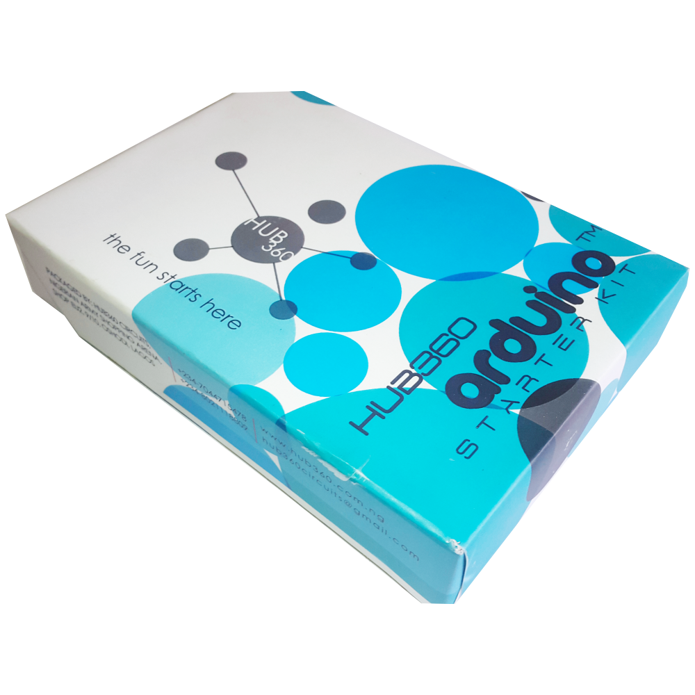
The Hub360 Arduino Starter Kit is a comprehensive package designed for beginners and enthusiasts looking to dive into the world of electronics and programming. This kit includes Arduino Uno, which is a microcontroller board based on the ATmega328P. The kit provides a variety of components and modules to help users learn and experiment with different electronic projects and concepts.
Key Features:
- Includes Arduino Uno board
- Comprehensive set of components and modules for various projects
- Ideal for beginners and hobbyists
- Detailed tutorial and project guide included
- USB interface for easy programming and power
- Compatible with Arduino IDE and various libraries
Technical Specifications:
- Microcontroller: ATmega328P
- Operating Voltage: 5V
- Input Voltage (recommended): 7-12V
- Digital I/O Pins: 14 (6 PWM outputs)
- Analog Input Pins: 6
- DC Current per I/O Pin: 20mA
- Flash Memory: 32KB (ATmega328P) of which 0.5KB used by bootloader
- SRAM: 2KB (ATmega328P)
- EEPROM: 1KB (ATmega328P)
- Clock Speed: 16 MHz
Kit Contents:
- ARDUINO BOARD 1
- ARDUINO USB CABLE 1
- ARDUINO BATTERY CONNECTOR 1
- 400 HOLE BREADBOARD 1
- LED (RED, YELLOW , GREEN, WHITE) 20
- RGB LED 1
- JUMPER WIRE(M-M, M-F, F-F) 120
- PHOTORESISTOR (LDR) 3
- MALE HEADERS 40
- ULTRASONIC SENSOR 1
- FLAME SENSOR 1
- TEMP./HUMIDITY SENSOR 1
- TILT SENSOR 1
- LASER SENSOR 1
- PIR MOTION SENSOR 1
- RESISTORS(220K, 1K, 10K,100K) 40
- 7 SEGMENT DISPLAY 1
- SG90 SERVO 1
- REMOTE CONTROL 1
- BUZZER 1
- 2N2222 2
- TSOP 1838 1
- RF TRANSMITTER 1
- RF RECEIVER 1
- TACT SWITCH 5
- 16*2 LCD DISPLAY
Applications:
- Learning basic electronics and programming
- Building interactive projects and prototypes
- Developing skills in microcontroller-based design
- Experimenting with sensors and actuators
- Creating DIY electronic devices
Usage:
- Setup:
- Connect the Arduino Uno board to your computer using the USB cable.
- Install the Arduino IDE and configure it to recognize the board.
- Programming:
- Write or upload sample code (sketches) to the Arduino board using the Arduino IDE.
- Utilize the provided components and modules to build and test different circuits.
- Experimentation:
- Follow the detailed tutorials and project guide to create various projects.
- Modify and expand on the sample projects to enhance learning and creativity.
Caution:
- Handle the components carefully to avoid damage.
- Ensure proper connections and polarity to prevent short circuits or component failure.
- Verify the code and circuit connections before powering the board.
Datasheet:
For detailed technical specifications of the Arduino Uno, refer to the Arduino Uno Datasheet.
|
|
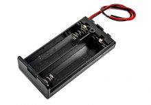
The 2 AA Battery Casing is a compact and convenient holder designed to securely house two AA batteries. This battery casing is ideal for providing a portable power source for various electronic projects, toys, remote controls, and other battery-powered devices. It features durable construction and easy-to-use connectors, ensuring reliable and consistent power delivery to your devices.
Key Features:
- Secure Housing: Holds two AA batteries securely in place
- Durable Construction: Made from high-quality plastic for long-lasting use
- Easy Installation: Snap-fit design for quick and easy battery replacement
- Wire Leads: Pre-attached wire leads for easy connection to your device
- Portable Power Source: Ideal for various DIY electronics and hobby projects
Technical Specifications:
- Battery Type: AA (1.5V each)
- Number of Batteries: 2
- Output Voltage: 3V (when using two 1.5V AA batteries)
- Material: High-quality plastic
- Wire Leads: Typically 150mm in length, pre-tinned for easy soldering
- Dimensions: Approximately 58mm x 33mm x 15mm (L x W x H)
- Weight: Lightweight design for portability
Applications:
- DIY electronics projects
- Battery-powered toys
- Remote controls
- Flashlights
- Educational kits and prototypes
- Portable power supplies
Usage:
- Insert two AA batteries into the casing, ensuring correct polarity.
- Connect the wire leads to your device’s power input, observing correct polarity.
- Secure the casing in place within your project or device.
- Replace batteries as needed to maintain power supply.
Caution:
- Ensure correct battery polarity to avoid damage to the casing or connected device.
- Use high-quality batteries for optimal performance.
- Do not mix old and new batteries or different types of batteries.
- Protect the casing from water and extreme temperatures to ensure longevity.
Datasheet:
For detailed technical specifications, refer to the 2 AA Battery Casing Datasheet.
|
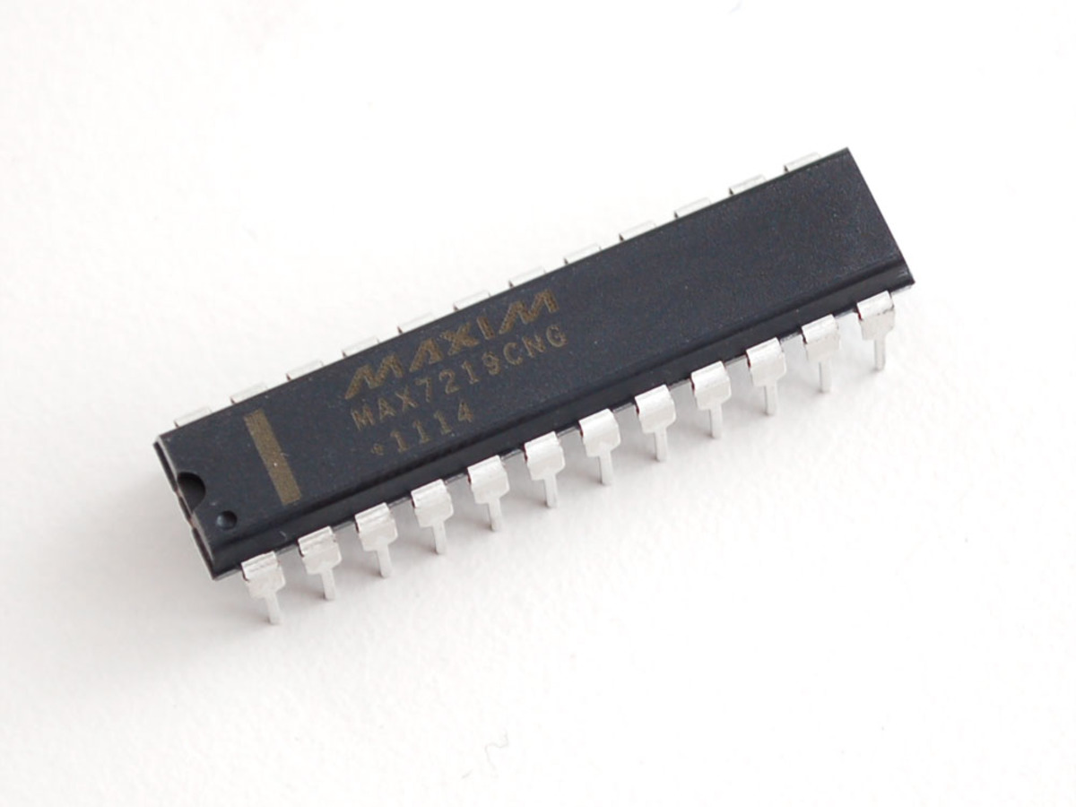
The MAX7219 is a versatile LED display driver IC from Maxim Integrated, designed for controlling 7-segment displays, bar graphs, and other LED configurations. It simplifies the process of driving multiple LEDs by handling the multiplexing and providing control over brightness and data. The MAX7219 is widely used in digital clocks, counters, and various LED display applications.
Key Features:
- Drives up to 8 digits of 7-segment displays or 64 individual LEDs
- Integrated BCD (Binary-Coded Decimal) to 7-segment decoding
- Serial communication via SPI interface
- Built-in display memory and digit drivers
- Adjustable brightness with 16 levels of intensity
- Low power consumption
- Easy cascading of multiple ICs for larger displays
Technical Specifications:
- IC Type: LED Display Driver
- Control Interface: SPI (Serial Peripheral Interface)
- Output Channels: 8 (for 7-segment displays) or 64 LEDs
- Brightness Levels: 16
- Operating Voltage: 4.0V to 5.5V
- Current Per Segment: Up to 40mA
- Current Per Digit: Up to 320mA
- Operating Temperature Range: -40°C to +85°C
- Package Type: DIP-24, SOIC-24, or TSSOP-24
Applications:
- Digital clocks and timers
- LED displays for counters and indicators
- Home appliances and consumer electronics
- Industrial equipment displays
- Prototyping and development projects
Usage:
- Connect the MAX7219 to your microcontroller via the SPI interface (DIN, CLK, CS).
- Connect the 7-segment displays or LEDs to the output pins of the MAX7219.
- Configure the display settings and data via the SPI communication protocol.
- Use the MAX7219 to drive and control the displays, adjusting brightness as needed.
Caution:
- Ensure proper connection of the SPI interface and power supply to avoid malfunction.
- Verify the current ratings and resistors used with the LEDs to prevent damage.
- Follow the manufacturer’s guidelines for wiring and programming.
Datasheet:
For detailed technical specifications, refer to the MAX7219 Datasheet.
|
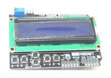
The LCD Keypad Shield is an expansion board designed to provide both an LCD display and a set of push-button inputs to a microcontroller or development board. It combines a 16×2 LCD display with a matrix of push-button controls, allowing for interactive and user-friendly interfaces in various electronic projects.
Key Features:
- Integrated LCD Display: Includes a 16×2 character LCD for displaying text and information.
- Push-Button Matrix: Features a matrix of 5 buttons for user input, often including directional arrows and an “OK” button.
- Compatible with Arduino: Designed to work with Arduino boards and other compatible platforms.
- Simple Interface: Connects to the microcontroller through standard header pins, making it easy to integrate.
- Backlight Option: Some versions include a backlight for better visibility in low-light conditions.
Technical Specifications:
- LCD Type: 16×2 Character LCD
- Button Matrix: Typically includes 5 buttons arranged in a matrix (Up, Down, Left, Right, and Select)
- Operating Voltage: Typically 5V, compatible with standard Arduino boards.
- Connection: Uses standard Arduino shield pin layout for easy attachment.
- Backlight: Optional, depending on the specific model.
Applications:
- User Interfaces: Ideal for creating user interfaces in electronics projects, such as menu systems and displays.
- Educational Projects: Useful for teaching and learning about LCD displays and button inputs.
- Prototyping: Facilitates rapid prototyping of interactive systems with visual and input capabilities.
- DIY Electronics: Suitable for hobbyists and makers working on projects requiring both display and control elements.
Datasheet:
For detailed technical specifications and wiring instructions, refer to the LCD Keypad Shield Datasheet.
|
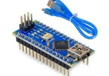
The Arduino Nano V3.0 is a compact, breadboard-friendly microcontroller board based on the ATmega328P. It is part of the Arduino platform and is designed for use in small projects and prototyping. The board includes a USB cable for easy connection to a computer for programming and power.
Key Features:
- ATmega328P microcontroller
- Compact size with 30mm x 18mm dimensions
- 22 digital I/O pins, of which 6 can be used as PWM outputs
- 8 analog input pins
- 32 KB Flash memory for program storage
- 2 KB SRAM for data storage
- 1 KB EEPROM for non-volatile data storage
- Built-in USB interface for easy programming
- Compatible with Arduino IDE for development
Technical Specifications:
- Microcontroller: ATmega328P
- Operating Voltage: 5V
- Input Voltage: 7-12V (through the power jack or USB)
- Digital I/O Pins: 22
- PWM Output Pins: 6
- Analog Input Pins: 8
- Flash Memory: 32 KB
- SRAM: 2 KB
- EEPROM: 1 KB
- Clock Speed: 16 MHz
- USB Interface: Mini-USB
- Dimensions: 30mm x 18mm
Applications:
- Prototyping and development for electronics projects
- Embedded systems and automation
- Robotics
- Sensor interfacing and data acquisition
- Educational projects and learning
Usage:
- Connection: Connect the Arduino Nano V3.0 to your computer using the included USB cable. The USB cable is used for both power and programming.
- Programming: Use the Arduino IDE to write and upload code to the board via the USB connection.
- Connection to Peripherals: Utilize the digital and analog I/O pins to connect sensors, actuators, and other peripherals.
- Power Supply: The board can be powered through the USB connection or via an external power source connected to the VIN pin.
Caution:
- Ensure correct voltage levels are used to avoid damaging the board. The recommended input voltage is 7-12V.
- Avoid short-circuiting the pins and connections.
- Handle the board and USB cable with care to prevent physical damage.
Datasheet:
For detailed technical specifications and pin configuration, refer to the Arduino Nano V3.0 Datasheet.
|
