Description |
The L7824 is a three-terminal positive voltage regulator that provides a fixed output of +24V. Designed for reliable and efficient voltage regulation, it is suitable for powering a range of electronic circuits and devices from a higher input voltage source. This regulator can supply up to 1.5A of current and includes built-in protection features to safeguard against thermal overload and short circuits.
Key Features:
- Fixed positive output voltage of +24V
- Capable of delivering up to 1.5A of current
- High voltage regulation with minimal dropout
- Built-in thermal overload and short-circuit protection
- Easy to use with minimal external components
- Ideal for applications requiring a stable +24V power supply
Technical Specifications:
- Output Voltage: +24V
- Maximum Output Current: 1.5A
- Input Voltage Range: Up to +35V
- Dropout Voltage: 2V (typical)
- Line Regulation: 0.01% (typical)
- Load Regulation: 0.1% (typical)
- Package Type: TO-220, D2PAK
Applications:
- Positive voltage power supplies
- Voltage regulation in electronic circuits
- Power management in devices requiring +24V
- Replacement for higher voltage linear power supplies
Usage:
- Connect the positive input voltage to the input terminal (IN).
- Connect the output terminal (OUT) to the load or circuit requiring +24V.
- Ensure the ground terminal (GND) is connected to the system ground.
- Use a heatsink if necessary to handle thermal dissipation, especially under high load conditions.
Caution:
- Do not exceed the maximum input voltage rating.
- Ensure proper heat dissipation to prevent overheating.
- Verify correct polarity to avoid damage to the regulator and connected components.
Datasheet:
For detailed technical specifications, refer to the L7824 Datasheet.
|
The 2N5551 is an NPN bipolar junction transistor (BJT) designed for general-purpose applications, including amplification and switching. It offers high voltage capabilities and high current handling, making it suitable for a wide range of electronic circuits, from audio amplifiers to power management systems.
Key Features:
- Type: NPN Bipolar Junction Transistor (BJT)
- High Voltage Rating: Capable of withstanding high voltage levels
- High Current Capability: Suitable for medium to high current applications
- High Gain: Provides effective amplification for various signals
- Compact Package: Available in a TO-92 package for easy integration
Technical Specifications:
- Collector-Emitter Voltage (Vce): 60V
- Collector-Base Voltage (Vcb): 60V
- Emitter-Base Voltage (Veb): 6V
- Collector Current (Ic): 15A
- Power Dissipation (Ptot): 1W
- DC Current Gain (hFE): 50 to 400
- Transition Frequency (ft): 100MHz
- Package Type: TO-92
Applications:
- Signal Amplification: Ideal for amplifying audio and low-frequency signals
- Switching: Suitable for switching applications in various electronic circuits
- Power Amplification: Used in power amplifiers and related circuits
- Power Management: Effective in power management and regulation systems
- General Purpose: Versatile for various general-purpose electronic applications
Usage:
- Circuit Design: Integrate the 2N5551 transistor into your circuit according to the desired application.
- Biasing: Properly bias the transistor to ensure optimal performance in amplification or switching.
- Connection: Connect the collector, base, and emitter terminals correctly in your circuit.
- Testing: Test the circuit to ensure the transistor operates as intended.
Caution:
- Voltage and Current Limits: Adhere to the maximum voltage and current ratings to prevent damage.
- Heat Dissipation: Ensure adequate heat management to avoid overheating, especially in high-current applications.
- Static Electricity: Handle with care to prevent damage from electrostatic discharge (ESD).
Datasheet:
For detailed technical specifications, refer to the 2N5551 Transistor Datasheet.
|
The L293 is a quadruple high-current half-H driver designed to provide bidirectional drive currents of up to 1A at voltages from 4.5V to 36V. It is ideal for driving inductive loads such as relays, solenoids, DC and stepping motors. The L293 IC is commonly used in robotics and embedded systems for motor control applications.
Key Features:
- Capable of driving two DC motors or one stepper motor
- Provides bidirectional drive currents up to 1A per channel
- Wide supply voltage range from 4.5V to 36V
- Separate input-logic supply
- Thermal shutdown protection
- High noise immunity
- Internal ESD protection
- Compatible with TTL and CMOS logic levels
Technical Specifications:
- Supply Voltage (VCC1 – Logic): 4.5V to 7V
- Supply Voltage (VCC2 – Motor): 4.5V to 36V
- Output Current: 1A per channel (continuous)
- Peak Output Current: 2A per channel (non-repetitive, t < 5ms)
- Input Voltage High: 2.3V (min)
- Input Voltage Low: 1.5V (max)
- Enable Voltage High: 2.3V (min)
- Enable Voltage Low: 1.5V (max)
- Power Dissipation: 5W (typical)
- Operating Temperature Range: 0°C to +70°C
- Package Type: 16-pin DIP (Dual In-line Package), SOIC (Small Outline Integrated Circuit), or TSSOP (Thin Shrink Small Outline Package)
Applications:
- Robotics
- Motor control for DC motors and stepper motors
- Relay drivers
- Solenoid drivers
- High current LED drivers
- Automotive applications
Usage:
- Connection:
- Connect VCC1 to the logic voltage (4.5V to 7V).
- Connect VCC2 to the motor voltage (4.5V to 36V).
- Connect the input pins (IN1, IN2, IN3, IN4) to the microcontroller or control logic.
- Connect the output pins (OUT1, OUT2, OUT3, OUT4) to the motor terminals.
- Enable the channels by connecting the enable pins (EN1, EN2) to the logic high or via PWM signals for speed control.
- Control:
- Use the input pins to set the direction of the motor rotation.
- Use PWM on the enable pins to control the speed of the motors.
- Protection:
- Ensure proper heat sinking or cooling as the IC can get hot under high loads.
- Use external diodes if necessary to protect against back EMF generated by motors.
Caution:
- Ensure the total current does not exceed the maximum ratings of the IC.
- Provide adequate cooling to prevent thermal shutdown.
- Avoid short circuits and excessive voltage spikes.
Datasheet:
For detailed technical specifications, refer to the L293 Motor Driver IC Datasheet.
|
Description:
The 5mm 8×8 Dot Matrix is a versatile LED display module designed for a wide range of applications, including text display, graphical displays, and status indicators. The matrix consists of 64 individual LEDs arranged in an 8×8 grid, providing bright and clear visual output. This module is ideal for use in digital clocks, scoreboards, message boards, and various electronic projects.
Key Features:
- Matrix Configuration: 8×8 grid of LEDs, offering a total of 64 LEDs
- LED Size: 5mm diameter LEDs for bright and clear display
- Display Type: Suitable for alphanumeric characters and simple graphics
- Brightness: High brightness for visibility in various lighting conditions
- Driver Compatibility: Compatible with common LED drivers and controllers for easy integration
- Versatile Use: Can be used for creating dynamic visual effects, messages, and notifications
Technical Specifications:
- Matrix Size: 8×8 (64 LEDs)
- LED Diameter: 5mm
- Operating Voltage: Typically 5V DC
- Color: Typically single color (e.g., red, green, or blue)
- Interface: Requires compatible LED driver/controller for operation
- Dimensions: Compact design for easy integration into various projects
- Weight: Lightweight for easy mounting
Applications:
- Digital Displays: Used in digital clocks and scoreboards for clear numeric and text display
- Message Boards: Ideal for scrolling or static messages in public or private displays
- Decorative Lighting: Useful for creating visual effects and lighting patterns
- Electronic Projects: Suitable for hobbyist projects involving LED display
|
The P87C51 is an 8-bit microcontroller from the MCS-51 family, widely used in embedded systems and applications requiring control and automation. It features a robust set of peripherals and is compatible with the standard 8051 instruction set, making it suitable for various industrial, consumer, and automotive applications.
Key Features:
- 8-bit microcontroller based on the MCS-51 architecture
- 4KB of in-system programmable ROM
- 128 bytes of on-chip RAM
- 32 programmable I/O lines
- Two 16-bit timer/counters
- Full-duplex UART for serial communication
- On-chip oscillator and clock circuitry
- Interrupt support with two priority levels
- Watchdog timer for system reliability
- Low-power idle and power-down modes
Technical Specifications:
- CPU: 8-bit 8051 core
- ROM: 4KB
- RAM: 128 bytes
- EEPROM: None (external EEPROM can be used if needed)
- I/O Pins: 32 (four 8-bit ports)
- Timers/Counters: Two 16-bit
- Serial Communication: UART
- Operating Voltage: 4.0V to 5.5V
- Clock Frequency: Up to 24 MHz
- Power Consumption: Low power modes available
- Operating Temperature Range: -40°C to +85°C
- Package Type: DIP-40, PLCC-44, or QFP-44
Applications:
- Industrial control systems
- Consumer electronics
- Automotive systems
- Home automation
- Robotics
- Data acquisition systems
Usage:
- Program the P87C51 using an appropriate programmer with the desired firmware.
- Connect the necessary peripherals and sensors to the microcontroller’s I/O pins.
- Configure the microcontroller’s settings and features via software.
- Integrate the microcontroller into your electronic circuit for specific tasks and control functions.
Caution:
- Ensure proper handling and storage to avoid damage from electrostatic discharge (ESD).
- Verify correct power supply voltage and connections before powering the device.
- Follow the manufacturer’s guidelines for programming and operation.
Datasheet:
For detailed technical specifications, refer to the P87C51 Datasheet.
|
The Professional Soldering Iron 60W is designed for precision soldering tasks in electronics and electrical work. Its high power output ensures quick heating and efficient soldering, making it ideal for both hobbyists and professionals.
Key Features:
- High Power: 60W output for fast heating and consistent performance.
- Adjustable Temperature Control: Allows precise temperature adjustments for different soldering tasks.
- Ergonomic Design: Comfortable grip for extended use and improved control.
- Fast Heat-Up: Quickly reaches operating temperature to reduce waiting time.
- Durable Tip: Long-lasting soldering tip designed for reliable performance.
Technical Specifications:
- Power: 60W
- Temperature Range: 200°C to 450°C (392°F to 842°F)
- Tip Type: Replaceable
- Handle Type: Ergonomic, heat-resistant
- Heat-Up Time: < 30 seconds
- Cord Length: 1.2 meters
- Input Voltage: 220V AC (or according to regional standards)
- Weight: Approximately 150 grams
Applications:
- Electronics assembly and repair
- PCB soldering
- Electrical connections
- Fine precision soldering work
Usage:
- Plug the soldering iron into a suitable power outlet.
- Set the desired temperature using the temperature control knob.
- Wait for the iron to reach the set temperature before using it for soldering.
- Use the soldering tip to apply solder to the joints or components as needed.
Caution:
- Handle with care as the soldering iron becomes very hot.
- Ensure proper ventilation while soldering to avoid inhaling fumes.
- Allow the soldering iron to cool down before storing.
|
The LM324 is a quad operational amplifier IC that consists of four independent, high-gain, internally frequency-compensated op-amps designed to operate from a single power supply over a wide voltage range. It is suitable for various applications in both analog and digital circuits, including amplifiers, filters, and oscillators. The LM324 is known for its low power consumption and versatility, making it a popular choice in many electronic designs.
Key Features:
- Four independent op-amps in a single package
- Single supply operation: 3V to 32V
- Dual supply operation: ±1.5V to ±16V
- Low supply current: 700µA per amplifier
- Internally frequency-compensated for unity gain
- Wide bandwidth: 1 MHz
- Low input offset voltage: 2mV
- Common-mode input voltage range includes ground
- Output voltage range includes ground
Technical Specifications:
- Number of Amplifiers: 4
- Supply Voltage Range: Single supply: 3V to 32V, Dual supply: ±1.5V to ±16V
- Input Offset Voltage: Typically 2mV
- Input Bias Current: Typically 20nA
- Supply Current: 700µA per amplifier
- Gain Bandwidth Product: 1 MHz
- Slew Rate: 0.5 V/µs
- Operating Temperature Range: 0°C to +70°C
- Package Types: DIP-14, SOIC-14, TSSOP-14
Applications:
- Signal conditioning
- Sensor interfacing
- Active filters
- Voltage followers
- Integrators and differentiators
- Oscillators
- Comparators
- Audio pre-amplifiers
Usage:
- Single Supply Operation:
- Connect the Vcc pin to the positive supply voltage and the GND pin to the ground.
- Configure the input and feedback components according to the desired application (e.g., amplification, filtering).
- Dual Supply Operation:
- Connect the positive supply voltage to the Vcc pin and the negative supply voltage to the Vee pin.
- Configure the input and feedback components according to the desired application.
- Common Applications:
- Use resistors, capacitors, and other passive components in the feedback loop to set the gain, frequency response, and other parameters of the op-amp circuit.
- Ensure the input voltage levels are within the specified common-mode range for proper operation.
Caution:
- Verify the supply voltage and ensure it is within the specified range to avoid damaging the IC.
- Handle the IC carefully to avoid electrostatic discharge (ESD) damage.
- Check the pin configuration and connections to prevent incorrect wiring and potential circuit malfunction.
Datasheet:
For detailed technical specifications, refer to the LM324 Datasheet.
|
The Allen key, also known as a hex key or hex wrench, is a small hand tool used to drive screws and bolts with hexagonal sockets. The Size 4 mm Allen key is designed to fit fasteners with a 4 mm hexagonal socket. This tool is commonly used in various mechanical, electrical, and DIY applications.
Key Features:
- Size: 4 mm (hexagonal socket size)
- Shape: L-shaped or T-shaped
- Material: Typically made from steel or chrome vanadium for durability and strength
- Finish: Often coated with black oxide or chrome plating for corrosion resistance
- Type: Can come in various designs such as short or long arm, ball-end, or standard
Technical Specifications:
- Hexagon Size: 4 mm
- Length: Varies depending on design (e.g., 60 mm to 150 mm for short arm, longer for T-handle or L-handle)
- Material: Steel, chrome vanadium, or other hardened materials
- Finish: Black oxide, chrome-plated, or other protective coatings
Applications:
- Mechanical Work: Used in automotive repair, machinery assembly, and other mechanical tasks.
- Furniture Assembly: Commonly used for assembling flat-pack furniture.
- Bicycles: Used for adjusting and tightening components on bicycles.
- Electronics: Helpful in assembling and repairing electronic devices with hex screws.
- DIY Projects: Essential for various home improvement and hobbyist tasks.
Datasheet:
Typically, Allen keys do not have detailed datasheets, but specifications can be obtained from this datasheet.
|
The UA741 is a general-purpose operational amplifier featuring offset-voltage null capability. The high-gain, internally frequency-compensated op-amp is designed to operate from a single or dual power supply over a wide range of voltages. It is an ideal choice for applications requiring low input bias current, low offset voltage, and high input impedance.
Key Features:
- Internally frequency compensated for unity gain
- Large signal voltage gain of 106 dB
- Wide power supply range: ±10V to ±15V
- Short-circuit protection
- Offset-voltage null capability
- Low input bias current: 80 nA (typical)
- High input impedance: 2 MΩ (typical)
- Low power consumption
- Compatible with standard LM741 pin configurations
Technical Specifications:
- Supply Voltage Range: ±10V to ±22V
- Input Offset Voltage: 1 mV (typical)
- Input Bias Current: 80 nA (typical)
- Input Impedance: 2 MΩ (typical)
- Output Impedance: 75Ω (typical)
- Large Signal Voltage Gain: 106 dB (typical)
- Unity-Gain Bandwidth: 1 MHz (typical)
- Slew Rate: 0.5 V/µs (typical)
- Common Mode Rejection Ratio (CMRR): 90 dB (typical)
- Power Supply Rejection Ratio (PSRR): 96 dB (typical)
- Operating Temperature Range: 0°C to +70°C
- Package Types: 8-pin PDIP, SOIC, TO-99
Applications:
- Signal conditioning
- Voltage followers
- Integrators and differentiators
- Active filters
- General-purpose analog applications
- Audio amplifiers
- Industrial controls
- Data acquisition systems
Usage:
- Connection:
- Connect the power supply to the V+ and V- pins.
- Connect the input signal to the inverting (−) or non-inverting (+) input pin.
- Connect the output to the desired load or next stage of the circuit.
- Use the offset null pins if necessary to adjust the input offset voltage.
- Configuration:
- Configure the op-amp in the desired configuration (e.g., voltage follower, inverting amplifier, non-inverting amplifier) by connecting the appropriate feedback components.
- Adjust the gain and frequency response using external resistors and capacitors.
- Protection:
- Use proper decoupling capacitors on the power supply lines to reduce noise and improve stability.
- Ensure the op-amp is within the recommended supply voltage range to prevent damage.
Caution:
- Observe proper handling procedures to avoid electrostatic discharge (ESD) damage.
- Ensure the input signals are within the common-mode voltage range to prevent improper operation.
- Avoid exceeding the maximum ratings for voltage, current, and temperature.
Datasheet:
For detailed technical specifications, refer to the UA741 Op-Amp Datasheet.
|
The S9018 is a general-purpose NPN bipolar junction transistor (BJT) used for low-power amplification and switching applications. It features a high gain, low noise, and good frequency response, making it suitable for various electronic circuits, including signal amplification, switching, and low-level audio frequency applications.
Key Features:
- Type: NPN Bipolar Junction Transistor (BJT)
- High Gain: High current gain (hFE) for effective amplification
- Low Noise: Suitable for low noise applications
- Good Frequency Response: Effective in high-frequency applications
- Compact Package: Available in a TO-92 package for easy integration
Technical Specifications:
- Collector-Emitter Voltage (Vce): 20V
- Collector-Base Voltage (Vcb): 25V
- Emitter-Base Voltage (Veb): 5V
- Collector Current (Ic): 50mA
- Power Dissipation (Ptot): 300mW
- DC Current Gain (hFE): 120 to 800
- Transition Frequency (ft): 600MHz
- Noise Figure: ≤ 10dB
- Package Type: TO-92
Applications:
- Signal Amplification: Used in low-power amplification circuits
- Switching Applications: Suitable for low-power switching applications
- Audio Frequency Circuits: Ideal for low-level audio amplification
- RF Applications: Effective in radio frequency applications due to its high frequency response
- General Purpose: Commonly used in various general-purpose electronic circuits
Usage:
- Circuit Design: Integrate the S9018 transistor into your circuit design based on the required application.
- Biasing: Properly bias the transistor for optimal performance in amplification or switching.
- Connection: Connect the collector, base, and emitter terminals appropriately in the circuit.
- Testing: Test the circuit to ensure the transistor is functioning as expected in the desired application.
Caution:
- Voltage and Current Limits: Do not exceed the maximum voltage and current ratings to prevent damage.
- Heat Dissipation: Ensure adequate heat dissipation to avoid overheating, especially in high-frequency or high-current applications.
- Static Electricity: Handle with care to avoid damage from electrostatic discharge (ESD).
Datasheet:
For detailed technical specifications, refer to the S9018 Transistor Datasheet.
|
The Allen key, also known as a hex key or hex wrench, is a tool used to drive screws and bolts with hexagonal sockets. The Size 2 mm Allen key is designed for use with fasteners that have a 2 mm hexagonal socket. This size is commonly used in various precision and small-scale applications.
Key Features:
- Size: 2 mm (hexagonal socket size)
- Shape: Typically L-shaped or T-shaped
- Material: Often made from high-strength steel or chrome vanadium for durability
- Finish: Commonly coated with black oxide, chrome plating, or other protective finishes to resist corrosion
- Type: Available in different designs, such as short or long arm, and sometimes with a ball end for use at an angle
Technical Specifications:
- Hexagon Size: 2 mm
- Length: Varies by design, e.g., 40 mm to 100 mm for short arms, and longer for T-handle or L-handle versions
- Material: Steel, chrome vanadium, or other hardened materials
- Finish: Black oxide, chrome-plated, or other protective coatings
Applications:
- Precision Work: Ideal for tasks involving small screws and bolts, such as in electronics, small machinery, and model assembly.
- Model Building: Commonly used in assembling and repairing model kits and hobby projects.
- Bicycles: Useful for adjustments on bicycle components that require a small hex size.
- Electronics: Essential for assembling and servicing electronic devices with small hex screws.
- Furniture Assembly: Often used for small, precision parts in flat-pack furniture.
Datasheet:
Allen keys typically do not have detailed datasheets, but specifications can be obtained from the tool manufacturer or supplier.
|
A small magnifying glass is a handheld optical device used to magnify small objects, making them appear larger for easier viewing. It is commonly used in applications such as reading small text, inspecting small objects, detailed crafts, and electronics work. Small magnifying glasses are portable, easy to use, and often come with additional features like built-in lights for enhanced visibility.
Key Features:
- Magnification: Typically ranges from 2x to 10x magnification
- Lens Diameter: Small lens diameters, commonly around 25 mm to 75 mm
- Material: Lenses are usually made from glass or high-quality acrylic
- Handle: Ergonomically designed handles for comfortable grip
- Additional Features: Some models come with built-in LED lights for better illumination
Technical Specifications:
- Magnification Power: Commonly available in 2x, 3x, 5x, 7x, and 10x magnifications
- Lens Diameter: Varies from 25 mm to 75 mm
- Lens Material: Optical glass or acrylic
- Frame Material: Plastic or metal
- Handle: Often plastic, rubber-coated, or metal with ergonomic design
- Weight: Typically lightweight, around 20 g to 100 g
Applications:
- Reading: Enhances the readability of small text in books, newspapers, and maps.
- Crafts and Hobbies: Useful for detailed work in model building, jewelry making, and other crafts.
- Electronics: Assists in inspecting small components, solder joints, and circuit boards.
- Biology and Botany: Helps in examining small specimens like insects and plant parts.
- Everyday Use: Handy for reading labels, menus, and other small print items.
Datasheet:
Small magnifying glasses generally do not have detailed datasheets, but the manufacturer or supplier can provide specifications.
|
The TIP124 is an NPN Darlington transistor composed of two bipolar junction transistors (BJTs) configured in a Darlington pair. This configuration provides high current gain and allows it to switch large loads with relatively low control current.
Key Features:
- Transistor Type: NPN Darlington pair transistor.
- Maximum Collector-Base Voltage (V_CB): Typically 100V.
- Maximum Collector-Emitter Voltage (V_CE): Typically 100V.
- Maximum Emitter-Base Voltage (V_EB): Typically 5V.
- Collector Current (I_C): Rated up to 5A continuous.
- Power Dissipation (P_D): Maximum power dissipation is typically around 65W.
- Gain (h_FE): Very high current gain due to the Darlington configuration.
- Package Type: TO-220 package, which provides good thermal conductivity and mechanical strength.
Technical Specifications:
- Operating Temperature Range: Typically -65°C to +150°C.
- Package Type: TO-220, suitable for through-hole mounting.
- Mounting Style: Through-hole mounting for easy integration into circuit boards or heat sinks.
- Pin Configuration: Base (B), Collector (C), Emitter (E).
- Applications: Commonly used in power supply circuits, motor drivers, solenoid control, and other high-current switching applications.
Applications:
- Power Supply Circuits: Used for regulating and switching power supplies.
- Motor Drivers: Controls DC motors and stepper motors.
- Relay Drivers: Provides the necessary current to activate electromagnetic relays.
- General Switching: Suitable for various high-current switching applications.
Datasheet: For detailed technical information, refer to the TIP124 datasheet.
|
The Creality CR-6SE is a high-precision 3D printer designed for users seeking reliable, professional-quality prints. Known for its ease of use and innovative features, the CR-6SE offers an enhanced printing experience with a focus on accuracy, stability, and user convenience. Ideal for hobbyists, educators, and professionals, this 3D printer delivers excellent performance for a variety of projects, from prototypes to complex models.
Key Features:
- High Precision Printing: Delivers detailed and accurate prints with a layer resolution of 0.1 mm.
- Auto-Leveling System: Features an advanced leveling-free system for hassle-free setup.
- Silent Operation: Equipped with a silent motherboard and TMC2209 drivers for quiet printing.
- Sturdy Construction: Built with a robust aluminum frame for stability and durability.
- Modular Design: Easy to assemble and maintain with a modular design.
- Resume Printing Function: Capable of resuming printing after power outages or interruptions.
- Touch Screen Interface: 4.3-inch color touch screen for an intuitive user interface.
- Dual Z-Axis: Provides improved accuracy and stability for the Z-axis movement.
Technical Specifications:
- Build Volume: 235 x 235 x 250 mm
- Layer Resolution: 0.1 mm
- Printing Speed: Up to 100 mm/s
- Nozzle Diameter: Standard 0.4 mm (interchangeable)
- Filament Compatibility: PLA, ABS, TPU, PETG, and other 1.75 mm filaments
- Extruder Type: Single Bowden extruder
- Print Bed: Carborundum glass platform for better adhesion and easy removal of prints
- Connectivity: USB, SD card
- Operating Temperature: Nozzle: Up to 260°C, Bed: Up to 110°C
- Power Supply: Meanwell 24V 350W
Applications:
- Prototyping: Ideal for creating accurate and detailed prototypes.
- Education: Useful for educational purposes in schools and universities.
- Art and Design: Perfect for artists and designers creating intricate models.
- DIY Projects: Suitable for hobbyists and makers working on custom projects.
- Manufacturing: Can be used for small-scale manufacturing and production of parts.
Usage:
- Assembly: Follow the provided instructions to assemble the 3D printer.
- Leveling: Use the auto-leveling system to ensure the print bed is properly leveled.
- Loading Filament: Load the desired filament into the extruder.
- Printing: Upload the 3D model via USB or SD card and start the print job using the touch screen interface.
- Post-Processing: Remove the finished print from the bed and perform any necessary post-processing.
Caution:
- Safety: Always operate the printer in a well-ventilated area.
- Temperature: Handle heated components with care to avoid burns.
- Maintenance: Regularly clean and maintain the printer for optimal performance.
Datasheet:
For detailed technical specifications, refer to the Creality CR-6SE Datasheet.
|
The 20pF monolithic capacitor is a fixed-value ceramic capacitor designed for precise applications requiring a capacitance of 20 picofarads. Its monolithic construction ensures stability and reliability, making it suitable for high-frequency and analog circuit applications.
Key Features:
- Fixed capacitance of 20pF
- Monolithic ceramic construction
- Stable performance over temperature and voltage
- Compact size for space-constrained applications
- Suitable for high-frequency and RF applications
Technical Specifications:
- Capacitance: 20pF
- Tolerance: ±5% or ±10%
- Voltage Rating: Typically 50V to 100V
- Temperature Coefficient: Class 1
- Package Type: Through-hole
Applications:
- RF and microwave circuits
- Oscillators and filters
- Precision tuning and calibration
- High-frequency signal processing
Usage:
- Insert the capacitor into the designated position on the PCB.
- Solder the capacitor, ensuring proper connections and no short circuits.
- Verify the circuit’s operation after installation.
Caution:
- Ensure the voltage rating is appropriate for your application.
- Handle with care to avoid damage.
- Check for correct polarity if applicable.
|
The 4N35 is a general-purpose optocoupler that consists of an infrared LED and a silicon phototransistor. It is designed to provide electrical isolation between input and output circuits while allowing signal transmission. This optocoupler is widely used in applications requiring noise isolation, signal isolation, and interface compatibility between high voltage and low voltage systems.
Key Features:
- High isolation voltage (typically 5,000 Vrms)
- Fast switching speed
- Low input current requirements
- Wide operating temperature range
- Compact and reliable design
- Compatible with various digital and analog circuits
Technical Specifications:
- Isolation Voltage: 5,000 Vrms (min)
- Input LED Forward Voltage: 1.2V (typ), 1.5V (max)
- Input LED Forward Current: 10mA (typ), 60mA (max)
- Collector-Emitter Voltage (VCEO): 30V (max)
- Collector Current (IC): 50mA (max)
- Current Transfer Ratio (CTR): 20% to 300% (at IF = 10mA, VCE = 5V)
- Rise Time (tr): 3µs (typ)
- Fall Time (tf): 2µs (typ)
- Package Type: 6-pin DIP
- Operating Temperature Range: -55°C to +100°C
Applications:
- Signal isolation in communication systems
- Switching power supplies
- Microcontroller interface isolation
- Motor control circuits
- Industrial automation systems
- Data acquisition systems
Usage:
- Circuit Design:
- Connect the anode of the input LED to the control signal source and the cathode to the ground, through a current-limiting resistor.
- Connect the collector of the phototransistor to the load or the microcontroller input, and the emitter to the ground.
- Current Limiting:
- Calculate and use an appropriate current-limiting resistor for the LED input to ensure it operates within the specified current range.
- Isolation:
- Ensure that the input and output sides of the optocoupler are properly isolated to prevent electrical interference and maintain safety.
- Testing:
- Verify the functionality of the optocoupler by applying a control signal to the LED input and observing the output response.
Caution:
- Handle the optocoupler with care to avoid damage from electrostatic discharge (ESD).
- Verify the electrical ratings and ensure the device operates within specified limits to avoid damage.
- Keep the input and output circuits isolated to maintain the integrity of the isolation barrier.
Datasheet:
For detailed technical specifications, refer to the 4N35 Datasheet.
|
The ESP8266 01S is a low-cost WiFi module that allows microcontrollers to connect to a WiFi network and make simple TCP/IP connections using Hayes-style commands. It is an improved version of the popular ESP8266-01 module, featuring better stability and performance. The module is ideal for IoT (Internet of Things) applications, enabling devices to communicate wirelessly with the internet or local network.
Key Features:
- Integrated TCP/IP protocol stack
- WiFi 802.11 b/g/n support
- Built-in low-power 32-bit CPU, can also function as an application processor
- 1MB of Flash memory
- Supports AP (Access Point), STA (Station), and AP+STA modes
- UART interface for easy integration
- Wide range of GPIOs for connecting sensors and peripherals
- Compact and lightweight design
Technical Specifications:
- Microcontroller: Tensilica L106 32-bit RISC processor, running at 80 MHz
- Operating Voltage: 3.0V to 3.6V
- Flash Memory: 1MB
- RAM: 50 kB
- WiFi Standards: 802.11 b/g/n
- Frequency Range: 2.4 GHz to 2.5 GHz
- Data Rate: Up to 1 Mbps
- UART Baud Rate: 9600 bps (default)
- GPIO Pins: 2 (GPIO0 and GPIO2)
- Operating Current: 70 mA (typical)
- Deep Sleep Current: < 10 µA
- Operating Temperature: -40°C to +125°C
- Dimensions: 25mm x 15mm x 6mm
Applications:
- Internet of Things (IoT) devices
- Home automation
- Wireless sensor networks
- Remote data logging
- Smart appliances
- Wearable technology
- DIY electronics projects
Usage:
- Connection:
- Connect the VCC pin to a 3.3V power supply and GND to ground.
- Connect the TX and RX pins to the UART interface of the microcontroller (with proper voltage level shifting if necessary).
- Use GPIO0 and GPIO2 for additional control and sensor connections.
- Programming:
- Use AT commands to configure and control the module via a serial interface.
- Optionally, use the Arduino IDE or other compatible development environments to write custom firmware for the ESP8266.
- WiFi Configuration:
- Configure the WiFi settings (SSID and password) using AT commands or custom firmware.
- Establish TCP/IP connections for data communication with remote servers or local networks.
Caution:
- Ensure the module operates within the specified voltage range to avoid damage.
- Handle the module carefully to avoid static discharge and physical damage.
- Use proper level shifting for UART communication if connecting to a 5V microcontroller.
Datasheet:
For detailed technical specifications, refer to the ESP8266 01S Datasheet.
|
The GY-291 ADXL345 is a digital accelerometer module that measures acceleration in three axes (X, Y, and Z) and provides high-resolution data for gravity tilt and motion sensing applications. With its low power consumption and wide range of functionalities, it is ideal for various projects, including robotics, gaming, and industrial applications.
Key Features:
- Three-Axis Measurement: Measures acceleration in X, Y, and Z axes.
- High Resolution: 13-bit resolution with a measurement range of ±2g, ±4g, ±8g, or ±16g.
- Low Power Consumption: Operates on low power, making it suitable for battery-powered devices.
- Digital Output: I2C and SPI digital interfaces for easy integration with microcontrollers.
- Built-in Motion Detection: Features tap, double-tap, activity, inactivity, and free-fall detection.
- Tilt Sensing: Accurate gravity tilt sensing capabilities.
Technical Specifications:
- Supply Voltage: 3V to 5V
- Measurement Range: ±2g, ±4g, ±8g, ±16g
- Resolution: 13-bit
- Interface: I2C, SPI
- Data Rate: 0.1Hz to 3200Hz
- Operating Temperature Range: -40°C to +85°C
- Dimensions: 14mm x 13mm x 2mm
- Weight: 1g
Applications:
- Robotics: Motion and tilt sensing for robots and drones.
- Gaming: Enhances gaming experience by detecting motion and orientation.
- Industrial Automation: Vibration monitoring and tilt sensing in industrial machines.
- Wearable Devices: Motion detection in fitness trackers and smartwatches.
- DIY Projects: Suitable for various DIY electronics projects requiring motion sensing.
Datasheet:
For detailed technical specifications, refer to the ADXL345 Datasheet.
|
The LMV321IDBVR is a low power operational amplifier designed for general-purpose applications where low voltage, low power consumption, and small package size are critical.
Key Features:
- Supply Voltage: Typically operates from 2.7V to 5.5V.
- Low Quiescent Current: Helps in conserving power, suitable for battery-operated devices.
- Low Offset Voltage: Provides accurate amplification of small signals.
- Single Supply Operation: Suitable for applications with single power supply voltage.
- Rail-to-Rail Output: Capable of driving signals close to both supply rails.
- Small Package: Available in SOT-23-5 package, suitable for space-constrained applications.
Technical Specifications:
- Number of Channels: Single operational amplifier.
- Bandwidth: Typically ranges up to several MHz.
- Slew Rate: Provides fast response to input signals.
- Input Offset Voltage: Low input offset voltage for precision applications.
- Temperature Range: Typically operates from -40°C to +125°C.
- Applications: Ideal for battery-powered devices, sensor interfaces, signal conditioning, and portable electronics.
Datasheet:
For detailed technical information, refer to the LMV321IDBVR Datasheet.
|
The 2N3904 is an NPN bipolar junction transistor (BJT) designed for general-purpose low-power switching and amplification. Renowned for its high current gain and low noise, the 2N3904 is versatile and widely used in various electronic circuits, including signal processing, switching, and low-power amplification.
Key Features:
- Type: NPN Bipolar Junction Transistor (BJT)
- High Gain: Provides high current gain (hFE) for effective signal amplification
- Low Noise: Suitable for low-noise applications
- Compact Package: Available in a TO-92 package, ideal for space-constrained designs
Technical Specifications:
- Collector-Emitter Voltage (Vce): 40V
- Collector-Base Voltage (Vcb): 60V
- Emitter-Base Voltage (Veb): 6V
- Collector Current (Ic): 200mA
- Power Dissipation (Ptot): 625mW
- DC Current Gain (hFE): 30 to 300
- Transition Frequency (ft): 300MHz
- Package Type: TO-92
Applications:
- Signal Amplification: Ideal for use in low-power amplification circuits
- Switching: Suitable for general-purpose switching applications
- Audio Circuits: Effective in audio signal processing and low-power amplification
- General Purpose: Versatile for various electronic applications and projects
Usage:
- Circuit Design: Integrate the 2N3904 transistor into your circuit based on your specific application requirements.
- Biasing: Properly bias the transistor to ensure optimal performance for amplification or switching.
- Connection: Connect the collector, base, and emitter terminals as per your circuit design.
- Testing: Verify the transistor’s operation in your circuit to ensure it functions correctly.
Caution:
- Voltage and Current Ratings: Adhere to the maximum voltage and current ratings to prevent damage.
- Heat Management: Ensure adequate heat dissipation to avoid overheating, especially in high-current applications.
- Static Electricity: Handle with care to avoid damage from electrostatic discharge (ESD).
Datasheet:
For detailed technical specifications, refer to the 2N3904 Transistor Datasheet.
|
A small size dotted Vero board, also known as a stripboard or prototyping board, is a type of circuit board that is used for prototyping and building electronic circuits. It features a grid of holes with copper pads that allow components to be easily soldered onto the board. The dotted pattern provides flexibility in layout, making it ideal for custom circuit designs and small electronic projects.
Key Features:
- Dotted pattern for versatile circuit layout
- High-quality FR4 material for durability
- Copper pads for easy soldering
- Small size for compact projects
- Compatible with through-hole components
- Suitable for prototyping and custom circuit building
Technical Specifications:
- Material: FR4 (fiberglass epoxy laminate)
- Size: Typically around 70mm x 90mm (varies by manufacturer)
- Hole Pitch: 2.54mm (standard 0.1 inch grid)
- Hole Diameter: 1.0mm (suitable for most through-hole components)
- Thickness: 1.6mm
- Copper Thickness: 35µm (1oz/ft²)
- Pattern: Dotted (individual copper pads)
- Number of Holes: Varies by board size (e.g., 25×35 grid for 70mm x 90mm board)
Applications:
- Prototyping electronic circuits
- Custom circuit design
- DIY electronics projects
- Educational and learning purposes
- Small-scale production of custom circuits
Usage:
- Design the Circuit:
- Plan the layout of your components and connections on the Vero board.
- Place the Components:
- Insert the components into the holes according to your circuit design.
- Solder the Components:
- Solder the component leads to the copper pads on the reverse side of the board.
- Create Connections:
- Use solder bridges or wire links to create electrical connections between the copper pads as needed.
- Test the Circuit:
- Verify the circuit functionality and make any necessary adjustments or corrections.
Caution:
- Ensure proper soldering techniques to avoid short circuits or poor connections.
- Handle the board carefully to avoid damaging the copper pads or FR4 material.
- Verify the component placement and connections before powering the circuit.
|
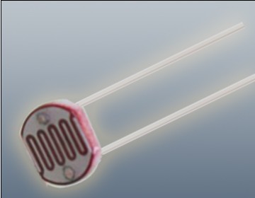
The Photoresistor LDR (Light Dependent Resistor) is a variable resistor whose resistance changes with the light intensity that falls upon it. It is widely used in light sensing applications and projects where detecting light levels is essential. LDRs are cost-effective, easy to use, and suitable for various electronic projects, including light meters, street lights, and other light-sensitive devices.
Key Features:
- Light Sensitivity: Resistance decreases with increasing light intensity
- Simple Interface: Easy to integrate with microcontrollers and analog circuits
- Low Cost: Economical solution for light detection
- Wide Range of Light Detection: Can detect various light levels from low to high intensity
- Compact Size: Fits easily into small projects
Technical Specifications:
- Resistance in Darkness: Typically 1MΩ (depending on specific model)
- Resistance in Bright Light: Typically 10-20kΩ (depending on specific model)
- Spectral Peak: Approximately 540nm (most sensitive to green light)
- Response Time: Rise time ~20ms, fall time ~30ms
- Operating Temperature Range: -30°C to +70°C
- Diameter: Typically 5mm to 10mm (depending on specific model)
Applications:
- Light Meters: Measure light intensity for photography and scientific applications.
- Street Lights: Automatic on/off control based on ambient light levels.
- Alarm Systems: Detect changes in light levels for security purposes.
- Consumer Electronics: Light-sensitive control in devices like clocks and displays.
- Educational Projects: Common component in learning modules for electronics.
Usage:
- Circuit Integration: Connect the LDR in a voltage divider circuit with a fixed resistor to create a variable voltage output based on light intensity.
- Microcontroller Interface: Read the voltage output from the LDR circuit using an analog input pin on a microcontroller.
- Programming: Write code to interpret the analog signal and perform actions based on light levels (e.g., turning on an LED when it gets dark).
- Testing: Calibrate the LDR circuit for the desired light sensitivity by adjusting the fixed resistor value.
Caution:
- Environment: Avoid exposure to extreme temperatures and humidity, which may affect the LDR’s performance.
- Handling: Handle with care to avoid damaging the sensitive surface of the LDR.
Datasheet:
For detailed technical specifications, refer to the Photoresistor LDR Datasheet.
|
The Arduino Uno R3 is a popular microcontroller board based on the ATmega328P. It is designed for easy integration into a wide range of applications, from hobby projects to professional prototyping. The board features a comprehensive set of I/O pins, communication interfaces, and power options, making it ideal for learning, experimentation, and development of embedded systems.
Key Features:
- Microcontroller: ATmega328P
- 14 Digital I/O Pins (6 PWM outputs)
- 6 Analog Input Pins
- Clock Speed: 16 MHz
- USB connection for programming and power
- 32KB Flash Memory (0.5KB used by bootloader)
- 2KB SRAM and 1KB EEPROM
- Built-in Power LED
- Supports SPI, I2C, and UART communication
Technical Specifications:
- Microcontroller: ATmega328P
- Operating Voltage: 5V
- Input Voltage (recommended): 7-12V
- Input Voltage (limits): 6-20V
- Digital I/O Pins: 14 (of which 6 provide PWM output)
- Analog Input Pins: 6
- DC Current per I/O Pin: 20 mA
- DC Current for 3.3V Pin: 50 mA
- Flash Memory: 32 KB (ATmega328P) of which 0.5 KB used by bootloader
- SRAM: 2 KB (ATmega328P)
- EEPROM: 1 KB (ATmega328P)
- Clock Speed: 16 MHz
- USB Connector: Type B
- Dimensions: 68.6 mm x 53.4 mm
- Weight: 25 g
Applications:
- Embedded system prototyping
- DIY electronics projects
- Educational tools for learning programming and electronics
- Robotics
- IoT (Internet of Things) devices
- Automation and control systems
Usage:
- Programming:
- Connect the Arduino Uno R3 to your computer using a USB cable.
- Open the Arduino IDE and select the board and correct COM port.
- Write your program (sketch) and upload it to the board.
- Powering:
- The board can be powered via the USB connection or with an external power supply (7-12V recommended).
- External power can be supplied through the power jack or via the Vin pin.
- Interfacing:
- Use the digital and analog I/O pins to connect sensors, actuators, and other components.
- Utilize communication interfaces like SPI, I2C, and UART for connecting to other devices and modules.
Caution:
- Avoid exceeding the maximum current ratings to prevent damage to the board.
- Ensure proper handling to avoid static discharge which can damage the microcontroller.
- Use a proper power supply to avoid over-voltage damage.
Datasheet:
For detailed technical specifications, refer to the Arduino Uno R3 Datasheet.
|
The S9014 is an NPN bipolar junction transistor (BJT) designed for general-purpose applications, including amplification and switching. It features high current gain and low noise, making it suitable for low-power electronic circuits. Its compact TO-92 package ensures ease of integration into various designs.
Key Features:
- Type: NPN Bipolar Junction Transistor (BJT)
- High Gain: High current gain (hFE) for effective amplification
- Low Noise: Suitable for low-noise applications
- Compact Package: Available in a TO-92 package for ease of use
Technical Specifications:
- Collector-Emitter Voltage (Vce): 50V
- Collector-Base Voltage (Vcb): 50V
- Emitter-Base Voltage (Veb): 6V
- Collector Current (Ic): 500mA
- Power Dissipation (Ptot): 400mW
- DC Current Gain (hFE): 100 to 600
- Transition Frequency (ft): 150MHz
- Package Type: TO-92
Applications:
- Signal Amplification: Ideal for low-power amplification circuits
- Switching: Suitable for low-power switching applications
- Audio Circuits: Used in audio frequency amplification and processing
- General Electronics: Commonly used in general-purpose electronic circuits and projects
Usage:
- Circuit Design: Integrate the S9014 transistor into your circuit based on the desired application.
- Biasing: Properly bias the transistor to ensure effective operation in amplification or switching roles.
- Connection: Connect the collector, base, and emitter terminals according to your circuit design.
- Testing: Verify the circuit operation to ensure the transistor is performing as expected.
Caution:
- Voltage and Current Ratings: Do not exceed the maximum rated voltage and current to avoid damage.
- Heat Management: Ensure adequate cooling to prevent overheating during operation.
- Handling: Handle with care to avoid damage from electrostatic discharge (ESD).
Datasheet:
For detailed technical specifications, refer to the S9014 Transistor Datasheet.
|
The 30cm Arduino Nano Cable is a compact, high-quality cable designed for connecting Arduino Nano boards to various peripherals or devices. Its short length makes it ideal for use in tight spaces or small projects where a longer cable might be cumbersome. This cable is typically used for programming the Arduino Nano or for connecting it to external components such as sensors, displays, or other microcontrollers.
Key Features:
- Length: 30 cm
- Connector Type: Compatible with Arduino Nano boards
- Connector Style: USB Type-B (or other variants depending on the model)
- Durability: High-quality construction for reliable performance
- Compatibility: Designed to fit Arduino Nano board pinouts
- Color: Varies by manufacturer
Technical Specifications:
- Cable Length: 30 cm
- Connector Type: USB Type-B to USB Type-A (or other variant as applicable)
- Material: Typically copper conductors with PVC insulation
- Data Transfer Rate: Depends on USB standard (usually USB 2.0)
- Operating Temperature Range: -20°C to +60°C
Applications:
- Connecting Arduino Nano boards to PCs for programming and communication
- Linking Arduino boards with external devices or peripherals
- Ideal for use in compact or portable projects where space is limited
Usage:
- Plug the USB Type-B connector into the Arduino Nano board.
- Connect the other end to a PC or other USB-enabled device.
- Ensure proper connection for reliable data transfer and device communication.
Caution:
- Avoid excessive bending or twisting of the cable to prevent damage.
- Ensure connectors are properly aligned before inserting to avoid physical damage.
- Use the cable within the specified temperature range to maintain performance.
Datasheet:
For detailed technical specifications, refer to the 30cm Arduino Nano Cable Datasheet.
|
The NEO-6M V2 GPS Module is a highly reliable and precise GPS receiver designed for various applications requiring accurate location tracking and timing. This module is based on the u-blox NEO-6M GPS receiver, providing high sensitivity and low power consumption. It is widely used in navigation, tracking, and timing applications.
Key Features:
- High sensitivity and accuracy
- Supports GPS, QZSS, and SBAS (WAAS, EGNOS, MSAS)
- Low power consumption
- Compact size and easy integration
- Built-in EEPROM for configuration storage
- Onboard battery for faster cold starts
- TTL logic level compatible
- Antenna connection with SMA connector
Technical Specifications:
- Receiver Type: 50 channels, GPS L1 C/A code
- Sensitivity: -161 dBm (tracking), -148 dBm (cold starts)
- Update Rate: Up to 5 Hz
- Accuracy: Position: 2.5 m CEP, Velocity: 0.1 m/s, Time: 30 ns
- Cold Start Time: 27 seconds
- Hot Start Time: 1 second
- Operating Voltage: 3.3V to 5V
- Power Consumption: 37 mA
- Communication Interface: UART (TTL), default baud rate: 9600 bps
- Antenna: External active antenna via SMA connector
- Dimensions: 25 mm x 35 mm x 6 mm
- Operating Temperature Range: -40°C to +85°C
Applications:
- Vehicle and personal navigation
- Asset tracking
- Drone and UAV navigation
- Timing applications
- Geocaching
- Marine navigation
- Location-based services
Usage:
- Power Supply: Connect the module to a 3.3V or 5V power supply.
- Antenna Connection: Attach an external active GPS antenna to the SMA connector.
- Communication Setup: Connect the UART pins (TX, RX) to a microcontroller or serial interface with a compatible TTL logic level.
- Configuration: Configure the module settings if necessary using appropriate software or commands.
- Data Reception: Receive GPS data through the UART interface and process it for your application.
- Position Fix: Wait for the module to acquire satellite signals and provide a position fix.
Caution:
- Ensure the module is powered within the specified voltage range.
- Use a suitable GPS antenna for optimal performance.
- Follow proper ESD handling procedures to prevent damage.
- Place the antenna in a location with a clear view of the sky for best signal reception.
Datasheet:
For detailed technical specifications, refer to the NEO-6M V2 GPS Module Datasheet.
|
The Raspberry Pi 3 Model A+ is a compact and cost-effective variant of the Raspberry Pi 3 series, designed to deliver high performance in a smaller form factor. It retains many of the features of the Raspberry Pi 3 Model B+ but in a more compact size, making it ideal for projects where space and cost are critical considerations. With its quad-core processor and integrated wireless connectivity, the Raspberry Pi 3 Model A+ is perfect for a wide range of applications, from IoT projects to DIY electronics and educational purposes.
Key Features:
- Quad-Core Processor: 1.4 GHz 64-bit quad-core ARM Cortex-A53 CPU for powerful performance.
- Wireless Connectivity: Integrated 2.4GHz and 5GHz IEEE 802.11.b/g/n/ac Wi-Fi and Bluetooth 4.2/BLE.
- Memory: 512MB LPDDR2 SDRAM.
- Compact Form Factor: Smaller size compared to the Raspberry Pi 3 Model B+, making it ideal for space-constrained projects.
- USB Port: One USB 2.0 port for connecting peripherals.
- HDMI Output: Full-size HDMI port for high-definition video output.
- Audio: 3.5mm audio jack and HDMI audio output.
- GPIO Pins: 40-pin GPIO header, compatible with Raspberry Pi HATs and add-on boards.
- Camera and Display Interfaces: CSI camera port for connecting a Raspberry Pi camera and DSI display port for connecting a Raspberry Pi touchscreen display.
- Micro SD Slot: For storage and operating system, located on the bottom of the board.
Technical Specifications:
- Processor: Broadcom BCM2837B0, Cortex-A53 (ARMv8) 64-bit SoC @ 1.4 GHz
- Memory: 512MB LPDDR2 SDRAM
- Wireless: 2.4GHz and 5GHz IEEE 802.11.b/g/n/ac Wi-Fi, Bluetooth 4.2, BLE
- USB Ports: 1 x USB 2.0
- Video & Audio Output: HDMI, composite video (via 3.5mm jack), and stereo audio
- GPIO: 40-pin header with 28 GPIO pins, 3.3V, 5V, ground, and various communication protocols (UART, I2C, SPI)
- Power: 5V/2.5A DC via micro-USB connector
- Dimensions: 65mm x 56.5mm x 15mm
- Weight: 29g
Applications:
- IoT Projects: Suitable for various Internet of Things applications.
- DIY Electronics: Ideal for hobbyist and maker projects.
- Educational Use: Perfect for learning programming, electronics, and computer science.
- Media Centers: Can be used as a media center with software like Kodi.
- Embedded Projects: Suitable for embedding into other projects due to its compact size.
- Home Automation: Useful for creating smart home applications.
Datasheet:
For detailed technical specifications, refer to the Raspberry Pi 3 Model A+ Datasheet.
|
The Allen key, also known as a hex key or hex wrench, is a tool designed for driving screws and bolts with hexagonal sockets. The Size 1.5 mm Allen key is specifically used for fasteners with a 1.5 mm hexagonal socket. This is one of the smallest Allen keys available and is typically used in precision applications where very small fasteners are required.
Key Features:
- Size: 1.5 mm (hexagonal socket size)
- Shape: Commonly L-shaped or T-shaped
- Material: Often made from high-quality steel or chrome vanadium for strength and durability
- Finish: Typically coated with black oxide, chrome plating, or other protective finishes to resist corrosion
- Type: Available in various designs including short or long arm, and sometimes with a ball end for ease of use in tight spaces
Technical Specifications:
- Hexagon Size: 1.5 mm
- Length: Varies by design, usually ranging from 30 mm to 80 mm for short arms, and longer for T-handle or L-handle versions
- Material: Steel, chrome vanadium, or other hardened materials
- Finish: Black oxide, chrome-plated, or other protective coatings
Applications:
- Precision Work: Ideal for tasks involving very small screws and bolts, such as in electronics and small machinery.
- Model Building: Commonly used in assembling and repairing model kits where very small fasteners are used.
- Bicycles: Useful for adjusting components on bicycles that require a small hex size.
- Electronics: Essential for assembling and servicing electronic devices with tiny hex screws.
- Jewelry Making: Used in precision applications where very small screws are common.
Datasheet:
Allen keys generally do not have detailed datasheets, but tool manufacturers or suppliers can provide specifications.
|
The Atmega 328P-PU is a high-performance, low-power 8-bit AVR microcontroller from Microchip Technology, commonly used in Arduino boards like the Arduino Uno. It features advanced RISC architecture with 32KB of ISP flash memory, 2KB of SRAM, and 1KB of EEPROM. This microcontroller is suitable for a wide range of applications, including embedded systems, consumer electronics, and DIY electronics projects.
Key Features:
- Advanced RISC architecture
- 32KB of in-system self-programmable flash memory
- 2KB SRAM and 1KB EEPROM
- 23 general-purpose I/O lines
- 32 general-purpose working registers
- Three flexible timer/counters with compare modes
- Internal and external interrupts
- Serial programmable USART
- Master/slave SPI serial interface
- On-chip analog comparator
- 10-bit ADC with 6 multiplexed channels
- Operating voltage range of 1.8V to 5.5V
- Low power consumption in active and sleep modes
Technical Specifications:
- Architecture: 8-bit AVR
- Flash Memory: 32KB
- SRAM: 2KB
- EEPROM: 1KB
- Clock Speed: Up to 20 MHz (with external crystal)
- Operating Voltage: 1.8V to 5.5V
- Digital I/O Pins: 23
- PWM Channels: 6
- Analog Input Channels: 6
- ADC Resolution: 10-bit
- Timers: 1 x 16-bit, 2 x 8-bit
- Communication Interfaces: USART, SPI, I2C
- Package Type: PDIP-28 (Plastic Dual In-line Package)
- Operating Temperature Range: -40°C to +85°C
Applications:
- Arduino development boards
- Consumer electronics
- Embedded systems
- Robotics
- Home automation
- DIY electronics projects
- Industrial automation
Usage:
- Programming:
- Use an AVR programmer or Arduino board to program the Atmega 328P-PU.
- Commonly programmed using the Arduino IDE for ease of use.
- Connect the microcontroller to your development environment using the appropriate hardware and software tools.
- Circuit Design:
- Integrate the Atmega 328P-PU into your circuit with necessary external components like crystal oscillators, capacitors, and resistors.
- Ensure proper power supply and grounding for stable operation.
- Interfacing:
- Utilize the I/O pins for interfacing with sensors, actuators, displays, and other peripherals.
- Use communication interfaces like USART, SPI, and I2C for data exchange with other devices.
Caution:
- Handle the microcontroller with care to avoid damage from electrostatic discharge (ESD).
- Ensure proper power supply voltage and connections to prevent damage.
- Follow the manufacturer’s guidelines for programming and operation.
Datasheet:
For detailed technical specifications, refer to the Atmega 328P Datasheet.
|
The Raspberry Pi 3 Transparent Injection Case is a protective enclosure designed for the Raspberry Pi 3 Model B and Model B+. It provides a clear, durable case that allows easy viewing of the Raspberry Pi while protecting it from dust, damage, and physical impact. The case is made from high-quality injection-molded plastic, ensuring a precise fit and a sleek, modern look.
Key Features:
- Transparent design for visibility of the Raspberry Pi board
- Injection-molded plastic construction for durability
- Precise cutouts for all ports, connectors, and GPIO pins
- Easy access to SD card slot and USB ports
- Ventilation slots for effective heat dissipation
- Simple snap-together assembly; no tools required
- Includes mounting hardware and rubber feet for stability
Technical Specifications:
- Material: Transparent injection-molded plastic
- Compatibility: Raspberry Pi 3 Model B and Model B+
- Color: Clear/Transparent
- Dimensions: Varies slightly by manufacturer (typically around 90mm x 60mm x 30mm)
- Weight: Varies slightly by manufacturer (typically around 50g)
Applications:
- Protecting Raspberry Pi 3 during use and handling
- Displaying the Raspberry Pi while maintaining access to ports
- Enclosing Raspberry Pi in a professional or educational setting
- Enhancing the aesthetics of Raspberry Pi-based projects
Usage:
- Place the Raspberry Pi 3 into the case, aligning it with the cutouts and mounting points.
- Snap the case parts together to secure the Raspberry Pi in place.
- Ensure all ports and connectors are accessible through the case openings.
- Mount the case using the included rubber feet or screws if required.
Caution:
- Handle the case carefully to avoid scratches or cracks.
- Ensure proper ventilation to prevent overheating of the Raspberry Pi.
- Verify that all connectors and ports are aligned and accessible before use.
Datasheet:
For detailed technical specifications, refer to the Raspberry Pi 3 Transparent Injection Case database.
|
The PIC16F876A is an 8-bit microcontroller from Microchip Technology, known for its versatility and ease of use in a wide range of embedded applications. It features a RISC architecture, with a rich instruction set and extensive peripheral support. This microcontroller is ideal for use in industrial automation, consumer electronics, automotive, and home appliances.
Key Features:
- 8-bit RISC architecture
- 14-bit instruction set
- 7.37 kB (8192 words) Flash memory for program storage
- 368 bytes SRAM for data storage
- 256 bytes EEPROM for non-volatile data storage
- 22 I/O pins for interfacing with external devices
- 3 Timers (2 x 8-bit, 1 x 16-bit)
- 10-bit ADC with 8 channels
- Capture/Compare/PWM (CCP) modules
- Enhanced USART module for serial communication
- Master Synchronous Serial Port (MSSP) supporting SPI and I2C
- Watchdog Timer with dedicated on-chip RC oscillator
- Programmable code protection
- In-Circuit Serial Programming (ICSP) via two pins
Technical Specifications:
- Package Types: 28-pin PDIP, SOIC, SSOP, QFN
- Operating Voltage: 2.0V to 5.5V
- Clock Speed: Up to 20 MHz
- Flash Memory: 7.37 kB
- SRAM: 368 bytes
- EEPROM: 256 bytes
- I/O Pins: 22
- Timers: Two 8-bit, one 16-bit
- ADC Resolution: 10-bit
- ADC Channels: 8
- Operating Temperature Range: -40°C to +85°C
Applications:
- Industrial automation
- Consumer electronics
- Automotive control systems
- Home appliances
- Security systems
- Data acquisition systems
- Robotics
Usage:
- Programming:
- Program the PIC16F876A using a compatible programmer or development kit.
- Utilize ICSP for convenient in-circuit programming and debugging.
- Peripheral Configuration:
- Configure I/O pins, timers, ADC, CCP modules, and communication interfaces via software.
- Use the integrated peripherals to interface with sensors, actuators, and other devices.
- Application Development:
- Write and upload firmware to the microcontroller using development environments such as MPLAB X IDE.
- Utilize libraries and example codes to speed up the development process.
- Deployment:
- Integrate the programmed microcontroller into your electronic circuit.
- Ensure proper power supply and signal connections to avoid damage and ensure optimal performance.
Caution:
- Handle the microcontroller with care to avoid damage from electrostatic discharge (ESD).
- Verify the correct power supply voltage and connections before powering the device.
- Follow the manufacturer’s guidelines for programming and operation to ensure reliability and longevity.
Datasheet:
For detailed technical specifications, refer to the PIC16F876A Datasheet.
|