|
Description |
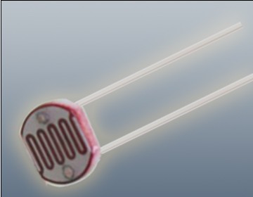
The Photoresistor LDR (Light Dependent Resistor) is a variable resistor whose resistance changes with the light intensity that falls upon it. It is widely used in light sensing applications and projects where detecting light levels is essential. LDRs are cost-effective, easy to use, and suitable for various electronic projects, including light meters, street lights, and other light-sensitive devices.
Key Features:
- Light Sensitivity: Resistance decreases with increasing light intensity
- Simple Interface: Easy to integrate with microcontrollers and analog circuits
- Low Cost: Economical solution for light detection
- Wide Range of Light Detection: Can detect various light levels from low to high intensity
- Compact Size: Fits easily into small projects
Technical Specifications:
- Resistance in Darkness: Typically 1MΩ (depending on specific model)
- Resistance in Bright Light: Typically 10-20kΩ (depending on specific model)
- Spectral Peak: Approximately 540nm (most sensitive to green light)
- Response Time: Rise time ~20ms, fall time ~30ms
- Operating Temperature Range: -30°C to +70°C
- Diameter: Typically 5mm to 10mm (depending on specific model)
Applications:
- Light Meters: Measure light intensity for photography and scientific applications.
- Street Lights: Automatic on/off control based on ambient light levels.
- Alarm Systems: Detect changes in light levels for security purposes.
- Consumer Electronics: Light-sensitive control in devices like clocks and displays.
- Educational Projects: Common component in learning modules for electronics.
Usage:
- Circuit Integration: Connect the LDR in a voltage divider circuit with a fixed resistor to create a variable voltage output based on light intensity.
- Microcontroller Interface: Read the voltage output from the LDR circuit using an analog input pin on a microcontroller.
- Programming: Write code to interpret the analog signal and perform actions based on light levels (e.g., turning on an LED when it gets dark).
- Testing: Calibrate the LDR circuit for the desired light sensitivity by adjusting the fixed resistor value.
Caution:
- Environment: Avoid exposure to extreme temperatures and humidity, which may affect the LDR’s performance.
- Handling: Handle with care to avoid damaging the sensitive surface of the LDR.
Datasheet:
For detailed technical specifications, refer to the Photoresistor LDR Datasheet.
|
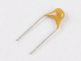
The 15pF monolithic capacitor is a small, high-precision capacitor used in various electronic circuits. Monolithic capacitors are known for their stability, reliability, and small size, making them suitable for high-frequency applications, filtering, and coupling in electronic devices.
Key Features:
- Capacitance value of 15pF
- Monolithic ceramic construction for stability and reliability
- Low equivalent series resistance (ESR)
- Small size for space-constrained applications
- Wide operating temperature range
Technical Specifications:
- Capacitance Value: 15pF
- Tolerance: ±5% (typical)
- Dielectric Material: Ceramic
- Voltage Rating: Typically 50V to 100V (check specific part for exact rating)
- Temperature Coefficient: ±10 ppm/°C (typical)
- Body Dimensions: Small, typically 2.0mm x 1.25mm (dimensions can vary)
Applications:
- High-frequency circuits and RF applications
- Filtering and coupling in electronic circuits
- Oscillator circuits
- Timing circuits
- Signal conditioning
Usage:
- Place the capacitor into the designated position on a PCB or breadboard.
- Solder the leads of the capacitor to secure it in place.
- Verify correct orientation and placement if polarized.
- Check circuit performance to ensure proper functionality after installation.
Caution:
- Ensure the capacitor is within its voltage rating to prevent breakdown.
- Handle with care to avoid physical damage.
- Verify the capacitance value with a meter before installation to ensure it meets specifications.
|
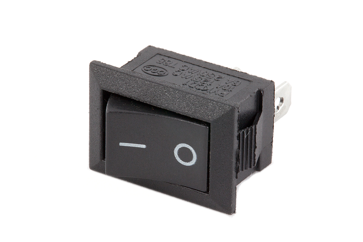
A switch is an electrical component used to make or break a connection in an electrical circuit. It allows the user to control the flow of electricity by toggling between an open (off) and closed (on) position. Switches are essential components in various applications, from household appliances to industrial machinery.
Key Features:
- Function: Controls the flow of electrical current
- Types: Available in various types, including toggle, push-button, rocker, slide, and rotary
- Design: Can be designed for single or multiple circuits
- Mounting Options: Options include panel-mount, surface-mount, and through-hole
Technical Specifications:
- Type: Varies by application (e.g., toggle, push-button, rocker, slide, rotary)
- Contact Rating: Typically specified in voltage and current ratings (e.g., 250V AC, 10A)
- Mechanical Life: Number of cycles the switch can handle before failure (e.g., 1,000,000 cycles)
- Electrical Life: Number of cycles the switch can handle under load (e.g., 100,000 cycles)
- Mounting Type: Can be panel-mount, surface-mount, or through-hole
- Actuation Force: Force required to operate the switch (e.g., 1-5N)
- Insulation Resistance: Resistance to electrical leakage (e.g., >100MΩ)
Applications:
- Household Appliances: Control of lights, fans, and other devices
- Industrial Equipment: Machinery and control panels
- Automotive: Control functions in vehicles
- Consumer Electronics: Power and function controls in gadgets
- Computers: Power buttons and user interface controls
Usage:
- Mounting: Install the switch according to its mounting type.
- Wiring: Connect the switch to the electrical circuit as per its contact ratings.
- Operation: Toggle, push, or slide the switch to control the flow of electricity.
Caution:
- Voltage and Current Ratings: Ensure the switch is rated for the voltage and current of your application to prevent overheating and failure.
- Proper Mounting: Securely mount the switch to avoid mechanical damage.
- Handling: Avoid applying excessive force or impact to prevent damage.
|
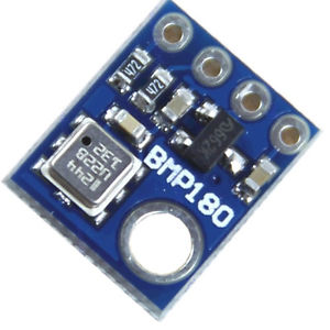
The BMP180 is a high-precision digital barometer and altitude sensor from Bosch, designed to measure atmospheric pressure and temperature. It is commonly used in applications requiring accurate altitude measurement and weather monitoring. The BMP180 provides reliable data for various applications including GPS, weather stations, and altitude tracking in wearable devices.
Key Features:
- Accurate barometric pressure and temperature measurement
- Digital interface with I²C or SPI communication
- High resolution with 0.03 hPa pressure measurement accuracy
- Compact and low-power design
- Built-in calibration for precise readings
- Wide operating temperature range
Technical Specifications:
- Sensor Type: Barometric Pressure and Temperature Sensor
- Communication Protocol: I²C (default), SPI (optional)
- Pressure Range: 300 hPa to 1100 hPa
- Pressure Accuracy: ±1 hPa (typical)
- Temperature Range: -40°C to +85°C
- Temperature Accuracy: ±1°C
- Resolution: 0.03 hPa for pressure
- Operating Voltage: 1.8V to 3.6V
- Current Consumption: 3µA (typical in sleep mode), 10µA (typical in measurement mode)
- Package Type: LGA-8 (Leadless Grid Array)
Applications:
- Altitude and weather tracking
- GPS altitude calibration
- Pressure-based data logging
- Environmental monitoring
- Wearable devices and consumer electronics
Usage:
- Connect the BMP180 sensor to your microcontroller or development board using I²C or SPI interface.
- Power the sensor with a voltage within the operating range (1.8V to 3.6V).
- Use the appropriate library or driver for the I²C or SPI protocol to interface with the sensor.
- Retrieve and process pressure and temperature data according to your application needs.
Caution:
- Ensure proper voltage supply to avoid damage to the sensor.
- Handle the sensor carefully to prevent mechanical damage or contamination.
- Verify correct wiring and communication protocol settings for accurate readings.
Datasheet:
For detailed technical specifications, refer to the BMP180 Datasheet.
|
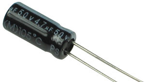
The 4.7µF 50V electrolytic capacitor is a polarized capacitor commonly used in electronic circuits for applications such as filtering, coupling, and decoupling. With a capacitance of 4.7 microfarads and a voltage rating of 50 volts, this capacitor provides reliable performance in a variety of electronic devices.
Key Features:
- Capacitance: 4.7µF
- Voltage Rating: 50V
- Polarized electrolytic design
- High capacitance for compact size
- Reliable for circuit stability and performance
- Suitable for power supply filtering and signal coupling
Technical Specifications:
- Capacitance: 4.7µF (microfarads)
- Voltage Rating: 50V DC
- Tolerance: Typically ±20%
- Temperature Range: -40°C to +85°C
- Package Type: Radial
Applications:
- Power supply smoothing and filtering
- Signal coupling and decoupling
- Audio and RF circuits
- Voltage regulation in electronic devices
- General electronic circuit use
Usage:
- Identify the positive (anode) and negative (cathode) leads of the capacitor.
- Insert the capacitor into the circuit board, ensuring correct polarity.
- Solder the leads securely to the board.
- Verify circuit operation after installation.
Caution:
- Avoid reversing polarity to prevent damage.
- Do not exceed the rated voltage.
- Handle carefully to avoid physical damage.
|
Description:
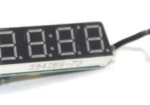
The Seven Segment High Precision Electronic Clock is a digital timekeeping device that displays the current time with high accuracy. Utilizing seven-segment LED displays, it provides a clear and easily readable representation of hours, minutes, and seconds. This clock is suitable for various applications, including industrial environments, educational settings, and personal use.
Key Features:
- High Precision Timekeeping: Ensures accurate time display with minimal drift over time.
- Seven-Segment LED Display: Provides clear and bright time readouts, easily visible from a distance.
- User-Friendly Interface: Simple controls for time setting and adjustments.
- Durable Construction: Built to withstand continuous use in various environments.
- Compact Design: Easily integrates into different spaces without occupying much room.
Technical Specifications:
- Display Type: Seven-segment LED
- Power Supply: Typically 5V DC
- Accuracy: ±1 second per month
- Operating Temperature Range: 0°C to +50°C
- Dimensions: Compact size for versatile installation options
- Weight: Lightweight design for ease of handling and mounting
Applications:
- Industrial Timing: Used in manufacturing plants and workshops for precise timekeeping.
- Educational Settings: Ideal for classrooms and laboratories for teaching time management and electronics.
- Personal Use: Suitable for home and office use to keep accurate track of time.
- Public Spaces: Can be installed in public areas such as lobbies, halls, and waiting rooms for time display.
|
The 4 Channel Remote Control with Receiver is designed for controlling toy car chassis with ease. It features four channels to manage two motors, allowing forward and reverse movement. This system is ideal for toy cars and other small-scale vehicles, but not suited for drones. It includes a remote control and receiver unit, with specific wiring instructions to ensure optimal performance.
Key Features:
- Four-channel control for two motors (forward and reverse)
- Wireless operation at 27 MHz frequency
- Includes remote control and receiver unit
- Compact design for easy integration into toy car chassis
- Available in Orange and Black (shipped randomly)
Technical Specifications:
- Frequency: 27 MHz
- Remote Control Voltage: 3V (2 AA batteries)
- Receiver Input Voltage: 4.5V – 6V (3-4 AA batteries)
- Remote Control Distance: 10 meters
- Receiver Output Voltage: 3V, suitable for 130, 140, and 260 motors
- Remote Control Size: 120mm x 85mm x 45mm (L x W x H)
- Receiver Board Size: 42mm x 27mm (L x W)
- Wiring Method: Red wire to positive power supply, black wire to negative pole; yellow and blue wires to forward and reverse motors, green and white wires to left and right steering motors; white wire with metal ring is the antenna.
Applications:
- Toy car chassis control
- Hobbyist projects
- Small-scale vehicle control
- DIY automation projects
Usage:
- Solder a 104 capacitor to the motor to ensure easy start and reduce interference with the receiver.
- Connect the remote control and receiver according to the provided wiring diagram.
- Insert AA batteries into both the remote control and receiver, ensuring correct voltage.
- Use the remote control to operate the toy car chassis, managing both motors for forward/reverse movement and steering.
Caution:
- Do not use lithium batteries as they can damage the board; use only AA batteries.
- Ensure correct wiring and battery installation to prevent malfunction.
- This remote is specifically for toy car chassis and is not suitable for drones.
|
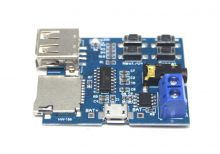
The MP3 Lossless Decoding and Amplifier Board is a versatile module designed to decode MP3 audio files and amplify the output for high-quality sound reproduction. It supports lossless decoding, ensuring that audio quality is preserved. This board is ideal for DIY audio projects, portable speakers, and other applications where high-fidelity audio is required.
Key Features:
- Lossless Decoding: Supports lossless MP3 decoding for high-quality audio playback.
- Built-in Amplifier: Integrated amplifier for direct connection to speakers.
- Multiple Input Sources: Supports USB, SD card, and auxiliary input.
- LCD Display: Provides information on track, playback status, and more.
- Remote Control: Includes remote control for convenient operation.
- Compact Design: Small and lightweight for easy integration into various projects.
- Stereo Output: Delivers clear stereo sound.
Technical Specifications:
- Input Voltage: 5V to 12V DC
- Supported Formats: MP3, WMA, WAV, FLAC
- Output Power: 2 x 3W (stereo output)
- Frequency Response: 20Hz to 20kHz
- Signal-to-Noise Ratio (SNR): ≥90dB
- Total Harmonic Distortion (THD): ≤0.05%
- Dimensions: 85mm x 55mm x 20mm
- Weight: Approximately 50g
Applications:
- Portable Speakers: Create custom portable speaker systems.
- Home Audio Systems: Integrate into home audio setups for high-quality music playback.
- DIY Audio Projects: Ideal for hobbyists building custom audio devices.
- Car Audio: Use in car audio systems for enhanced music playback.
- Public Address Systems: Implement in PA systems for clear and reliable audio output.
Datasheet:
For detailed technical specifications, refer to the MP3 Lossless Decoding and Amplifier Board Datasheet
|
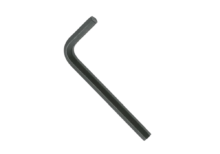
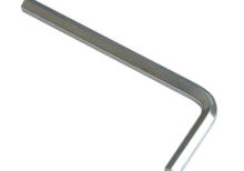
The Allen key, also known as a hex key or hex wrench, is a tool used to drive screws and bolts with hexagonal sockets. The Size 2 mm Allen key is designed for use with fasteners that have a 2 mm hexagonal socket. This size is commonly used in various precision and small-scale applications.
Key Features:
- Size: 2 mm (hexagonal socket size)
- Shape: Typically L-shaped or T-shaped
- Material: Often made from high-strength steel or chrome vanadium for durability
- Finish: Commonly coated with black oxide, chrome plating, or other protective finishes to resist corrosion
- Type: Available in different designs, such as short or long arm, and sometimes with a ball end for use at an angle
Technical Specifications:
- Hexagon Size: 2 mm
- Length: Varies by design, e.g., 40 mm to 100 mm for short arms, and longer for T-handle or L-handle versions
- Material: Steel, chrome vanadium, or other hardened materials
- Finish: Black oxide, chrome-plated, or other protective coatings
Applications:
- Precision Work: Ideal for tasks involving small screws and bolts, such as in electronics, small machinery, and model assembly.
- Model Building: Commonly used in assembling and repairing model kits and hobby projects.
- Bicycles: Useful for adjustments on bicycle components that require a small hex size.
- Electronics: Essential for assembling and servicing electronic devices with small hex screws.
- Furniture Assembly: Often used for small, precision parts in flat-pack furniture.
Datasheet:
Allen keys typically do not have detailed datasheets, but specifications can be obtained from the tool manufacturer or supplier.
|
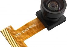
Specifications:
- Length: 21mm
- Pixel: 2 million
- Field of view: 160°
- Interface: DVP
- Lens: 1/4″
- Pixel: 1600*1200
- Aperture: 2.4
|
A line tracking sensor is an infrared-based module used for detecting and following lines or paths on surfaces. It is commonly employed in robotics and automated systems to navigate predefined routes or tracks.
Key Features:
- Sensor Type: Infrared (IR) sensor module.
- Detection Method: Typically uses infrared light emitted by LEDs and reflected off the surface.
- Detection Capability: Can detect lines of contrasting colors (typically black on white or vice versa).
- Output: Digital signals indicating line detection (e.g., high or low) or analog signals proportional to the position on the line.
- Operating Voltage: Usually operates at 5V DC.
- Adjustability: Often adjustable sensitivity to fine-tune detection based on line width and surface reflectivity.
- Integration: Compact and designed for easy integration into robotic systems or line-following vehicles.
- Mounting: Typically includes mounting holes or brackets for easy installation.
Technical Specifications:
- Dimensions: Compact size suitable for various robotic applications.
- Operating Range: Suitable for indoor and controlled outdoor environments.
- Response Time: Fast response to changes in line position.
- Operating Temperature: Typically -10°C to +50°C.
Applications:
- Automated guided vehicles (AGVs)
- Line-following robots
- Industrial automation
- Educational robotics projects
Datasheet: For detailed technical information, refer to the Line Tracking Sensor datasheet.
|
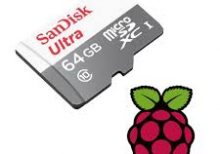
The Raspberry Pi SD Card 64GB is a high-capacity microSD card designed to provide ample storage for your Raspberry Pi projects. This microSD card offers a significant amount of space for operating systems, applications, data, and multimedia files, ensuring smooth and efficient performance. It is ideal for more complex and storage-intensive projects using any Raspberry Pi model with a microSD card slot.
Key Features:
- 64GB storage capacity
- Pre-loaded with the Raspberry Pi operating system (optional)
- High-speed data transfer rates
- Reliable and durable design
- Compatible with all Raspberry Pi models with a microSD card slot
- Ideal for projects requiring substantial storage space
- Easy to set up and use
Technical Specifications:
- Capacity: 64GB
- Format: MicroSDXC
- Speed Class: Class 10, UHS-I or UHS-II (varies by model)
- Read Speed: Up to 100MB/s (varies by model)
- Write Speed: Up to 90MB/s (varies by model)
- Operating Voltage: 2.7V to 3.6V
- Operating Temperature: -25°C to +85°C
- Storage Temperature: -40°C to +85°C
- Dimensions: Standard microSD card size
Applications:
- Raspberry Pi OS and application storage
- Data logging and storage
- Multimedia projects
- IoT applications
- Education and development projects
- Complex software development and testing
Datasheet:
For detailed technical information, please refer to the MicroSD Card Datasheet.
|
The Allen key, also known as a hex key or hex wrench, is a tool used to drive screws and bolts with hexagonal sockets. The Size 3 mm Allen key is designed for fasteners with a 3 mm hexagonal socket, making it suitable for various applications in mechanical, electrical, and DIY projects.
Key Features:
- Size: 3 mm (hexagonal socket size)
- Shape: Typically L-shaped or T-shaped
- Material: Often made from high-strength steel or chrome vanadium for durability and longevity
- Finish: Commonly coated with black oxide, chrome plating, or other protective finishes to resist corrosion
- Type: Available in different designs, such as short or long arm, and sometimes with a ball end for ease of use in tight spaces
Technical Specifications:
- Hexagon Size: 3 mm
- Length: Varies by design, e.g., 50 mm to 120 mm for short arms, and longer for T-handle or L-handle versions
- Material: Steel, chrome vanadium, or other hardened materials
- Finish: Black oxide, chrome-plated, or other protective coatings
Applications:
- Mechanical Work: Ideal for tasks involving screws and bolts in machinery and automotive applications.
- Furniture Assembly: Commonly used for assembling flat-pack furniture.
- Bicycles: Useful for adjusting and tightening components on bicycles.
- Electronics: Essential for assembling and repairing electronic devices with hex screws.
- DIY Projects: Suitable for various home improvement and hobbyist tasks.
Datasheet:
Allen keys generally do not have detailed datasheets, but tool manufacturers or suppliers can provide specifications.
|
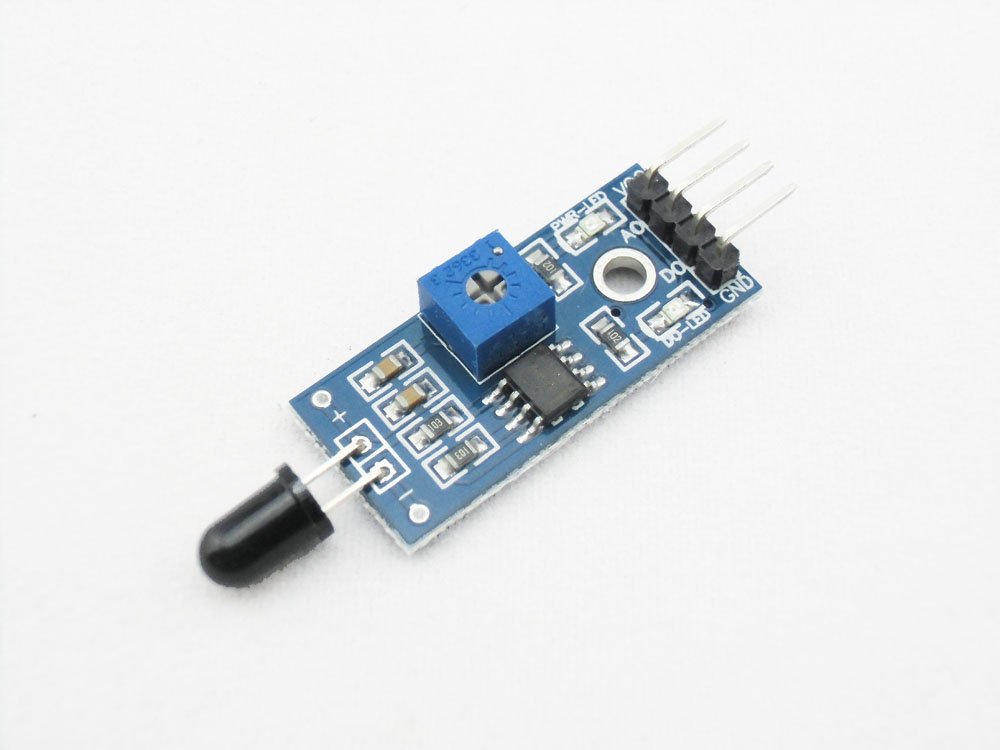
A flame sensor is an infrared (IR) detector used to detect the presence of flame or fire. It is typically used in fire detection and safety systems to provide early warning and activate safety measures. The sensor is sensitive to IR light emitted by flames and can be used in various applications, including security systems, fire-fighting robots, and automatic fire alarm systems.
Key Features:
- Detects infrared light emitted by flames
- High sensitivity and fast response time
- Analog and digital output signals
- Adjustable sensitivity via potentiometer
- Compact and easy to integrate into various systems
- Onboard indicator LED for detection status
Technical Specifications:
- Detection Range: Up to 100cm (varies by model and flame size)
- Wavelength Range: 760nm to 1100nm (IR spectrum)
- Operating Voltage: 3.3V to 5V
- Output Type: Digital (DO) and Analog (AO)
- Response Time: Typically less than 100ms
- Dimensions: Typically around 32mm x 14mm x 8mm (varies by manufacturer)
- Operating Temperature Range: -25°C to +85°C
Applications:
- Fire detection systems
- Security and alarm systems
- Fire-fighting robots
- Industrial safety systems
- Household safety devices
- DIY electronics projects
Usage:
- Connect the flame sensor to your microcontroller or development board, ensuring proper connection of the power supply (VCC, GND) and the output pins (DO, AO).
- Use the digital output (DO) to detect the presence of flame with a simple HIGH/LOW signal.
- Use the analog output (AO) to get a proportional value indicating the intensity of the detected flame.
- Adjust the sensitivity of the sensor using the onboard potentiometer if necessary.
- Implement code to monitor the sensor outputs and trigger appropriate actions or alarms when a flame is detected.
Caution:
- Ensure the sensor is correctly oriented and positioned to detect the flame source accurately.
- Avoid exposing the sensor to direct sunlight or strong artificial light to prevent false detections.
- Handle the sensor carefully to avoid damage to the sensitive IR components.
Datasheet:
For detailed technical specifications, refer to the specific product datasheet provided by the manufacturer.
|
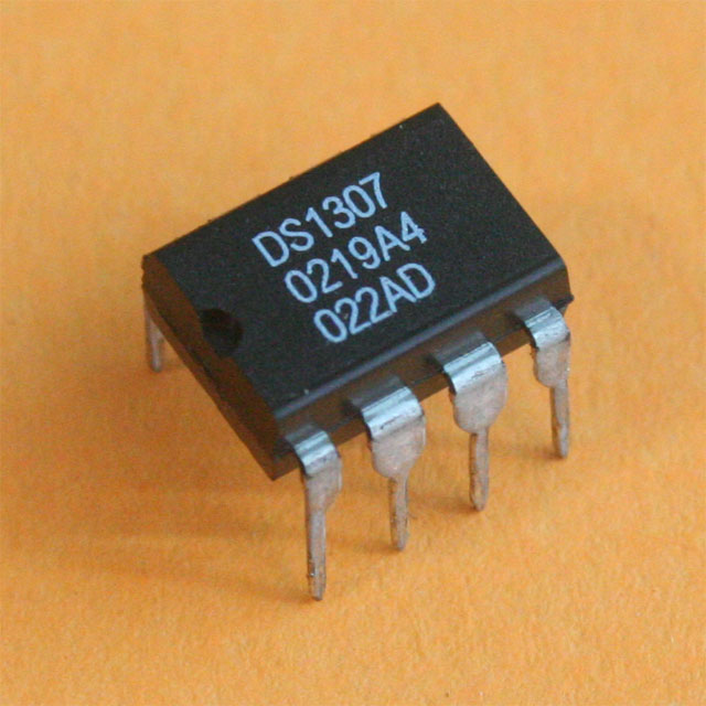
The DS1307 is a real-time clock (RTC) IC from Maxim Integrated, designed for accurate timekeeping in electronic systems. It provides reliable and precise time and date information and features a battery backup to maintain time during power outages. The DS1307 is commonly used in applications such as clocks, data loggers, and time-based control systems.
Key Features:
- Accurate real-time clock (RTC) with date and time functions
- Battery backup to maintain time during power loss
- Communicates via I²C interface
- High-precision timekeeping with a 32.768 kHz crystal oscillator
- Provides time and date information (seconds, minutes, hours, day, date, month, year)
- Low power consumption with battery operation
- Simple interface with microcontrollers and digital systems
Technical Specifications:
- IC Type: Real-Time Clock (RTC)
- Interface: I²C (2-wire)
- Operating Voltage: 4.5V to 5.5V
- Current Consumption: 1µA (battery backup mode), 1mA (active mode)
- Temperature Range: -40°C to +85°C
- Clock Frequency: 32.768 kHz (crystal oscillator)
- Accuracy: ±2 minutes per month at 25°C
- Battery Backup: CR2032 or equivalent lithium battery (not included)
- Package Type: DIP-8, SOIC-8
Applications:
- Real-time clocks for various electronic devices
- Data logging and timestamping
- Time-based control systems
- Embedded systems requiring accurate timekeeping
- Educational projects and prototypes
Usage:
- Connect the DS1307 chip to your microcontroller or development board using the I²C interface (SDA and SCL lines).
- Insert a compatible lithium battery to provide backup power for timekeeping.
- Use the appropriate I²C library or driver to interface with the DS1307 and configure the current date and time.
- Retrieve and process time and date information as required for your application.
Caution:
- Ensure proper installation of the battery to maintain time during power outages.
- Handle the IC with care to avoid damage to the pins or internal components.
- Verify I²C connections and power supply to ensure accurate operation.
Datasheet:
For detailed technical specifications, refer to the DS1307 Datasheet.
|
Description:
The 1-8S LiPo battery voltage detector with buzzer is an essential tool for monitoring and ensuring the safe operation of lithium polymer (LiPo) batteries used in RC models, drones, and other electronic devices. It provides real-time voltage detection for 1 to 8 series LiPo batteries, alerting users to low voltage conditions with an audible buzzer alarm. This compact device helps prevent over-discharge, which can damage batteries and reduce their lifespan, ensuring optimal performance and safety during use.
Key Features:
- Compatible Battery Types: 1-8S LiPo/Li-ion/LiMn/LiFe
- Voltage Detection Range: 2.7V to 25.2V (1S to 8S)
- Audible Buzzer Alarm: Alerts when voltage drops below preset levels
- Compact and Lightweight: Easy to carry and use in the field
- LED Indicators: Display battery voltage status for quick reference
- Reverse Polarity Protection: Prevents damage due to incorrect battery connection
Technical Specifications:
- Input Voltage: DC 5-27V (powered by the battery being tested)
- Accuracy: ±0.01V
- Operating Temperature: 0°C to 40°C
- Dimensions: Compact and portable design
- Weight: Lightweight for easy handling
Applications:
- RC Models (Cars, Planes, Boats)
- Drones and UAVs (Unmanned Aerial Vehicles)
- Portable Electronic Devices
- Battery Maintenance and Monitoring
|
The SIM800L GSM module is a compact and versatile GSM/GPRS module used for communication over cellular networks. It enables devices to send and receive SMS messages, make and receive voice calls, and connect to the internet using GPRS. This module is widely used in various applications including IoT projects, remote monitoring, and mobile communication.
Key Features:
- GSM/GPRS connectivity for voice, SMS, and data communication
- Supports multiple frequency bands for global compatibility
- Integrated antenna or external antenna support
- Simple AT command interface for control and configuration
- Low power consumption with various power-saving modes
Technical Specifications:
- Frequency Bands:
- GSM 850/900/1800/1900 MHz
- GPRS:
- Class 10 (up to 85.6 kbps download and upload)
- Power Supply:
- Operating Voltage: 3.4V to 4.4V
- Recommended Voltage: 4.0V
- Power Consumption: 20mA in idle mode, up to 2A during transmission (peak)
- Communication Interface:
- Serial UART (TX/RX) for AT command communication
- Operating Temperature Range:
- Antenna:
- Integrated or external antenna support (depending on the module variant)
- Size:
- Typically around 25mm x 23mm x 3mm (varies by manufacturer)
Applications:
- IoT (Internet of Things) devices
- Remote monitoring and control systems
- SMS-based applications
- GSM/GPRS-based data communication
- Voice communication applications
Usage:
- Power the Module: Connect the module to a stable power supply within the recommended voltage range.
- Connect to a Microcontroller: Use the UART interface to connect the SIM800L to a microcontroller or development board.
- Insert SIM Card: Insert a compatible SIM card into the SIM slot on the module.
- Send AT Commands: Use AT commands to configure the module, send SMS, make calls, or establish a GPRS connection.
- Integrate Antenna: Attach the antenna (if not integrated) to ensure proper signal reception and transmission.
Caution:
- Ensure proper voltage regulation to avoid damaging the module.
- Use a high-quality antenna to improve signal strength and communication reliability.
- Follow the manufacturer’s guidelines for handling and connecting the module to avoid damage and ensure optimal performance.
Datasheet:
For detailed technical specifications, refer to the SIM800L Datasheet.
|
The 10k Single Gear Potentiometer is an adjustable resistor with a resistance range of 0 to 10 kΩ. It features a single gear mechanism for manual adjustment of resistance. This type of potentiometer is commonly used in various electronic circuits to control voltage, adjust signal levels, and fine-tune parameters.
Key Features:
- Resistance: 10 kΩ
- Type: Single gear (single-turn) potentiometer
- Adjustment Mechanism: Manual adjustment using a rotary knob
- Mounting Type: Typically through-hole or surface-mount
- Material: Usually made from conductive carbon or metal film
Technical Specifications:
- Resistance Range: 0 to 10 kΩ
- Tolerance: Typically ±10% or ±20% (depends on the model)
- Number of Turns: Single-turn (single gear)
- Maximum Power Rating: Usually up to 0.5W
- Temperature Coefficient: Varies by model, typically around ±100 ppm/°C
- Mounting Type: Through-hole or surface-mount (varies by design)
- Adjustment Type: Rotary knob or shaft
Applications:
- Volume Control: Used in audio equipment to adjust volume levels.
- Signal Adjustment: Ideal for fine-tuning signals in electronic circuits.
- Calibration: Useful for calibrating and setting parameters in various devices.
- Control Interfaces: Applied in user interfaces for controlling devices and systems.
- Prototyping: Commonly used in electronic prototypes and experimental setups.
Datasheet:
For detailed technical information, refer to the datasheet of the specific 10k single gear potentiometer model, as specifications can vary based on the manufacturer and design.
|
The IRF740 is a high-voltage, high-current N-channel power MOSFET designed for switching and amplification applications. It is widely used in power supplies, motor controls, and other high-voltage circuits due to its efficient performance and reliable operation.
Key Features:
- N-channel enhancement mode MOSFET
- High voltage rating: 400V
- High current rating: 10A
- Low on-resistance for efficient switching
- Fast switching speed
- Rugged construction for high reliability
- Suitable for high-frequency applications
Technical Specifications:
- Type: N-channel MOSFET
- Drain-Source Voltage (Vds): 400V
- Continuous Drain Current (Id): 10A
- Pulsed Drain Current (Id, Pulse): 40A
- Gate-Source Voltage (Vgs): ±20V
- Rds(on): 1.0Ω (maximum) at Vgs = 10V
- Total Gate Charge (Qg): 67nC (typical)
- Gate-Source Threshold Voltage (Vgs(th)): 2.0V – 4.0V
- Power Dissipation (Pd): 125W
- Operating Temperature Range: -55°C to +150°C
- Package Type: TO-220
Applications:
- Switched-mode power supplies (SMPS)
- Motor control circuits
- Inverters and converters
- High-voltage DC-DC converters
- Load switches
- Lighting ballasts
- Audio amplifiers
Usage:
- Connect the drain terminal to the high-voltage load.
- Connect the source terminal to the ground or low-side of the circuit.
- Apply a suitable gate voltage (Vgs) to control the switching operation.
- Use a gate resistor if needed to control the switching speed and reduce noise.
- Ensure proper heat sinking to manage power dissipation and avoid overheating.
Caution:
- Handle the MOSFET carefully to avoid damage from electrostatic discharge (ESD).
- Verify the voltage and current ratings before use to ensure compatibility with your circuit.
- Ensure adequate cooling and heat dissipation to prevent thermal overload.
Datasheet:
For detailed technical specifications, refer to the IRF740 Datasheet.
|
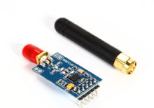
The Industrial Grade CC1101 Wireless Module is a high-performance, low-power radio transceiver module based on the CC1101 chip from Texas Instruments. It is designed for industrial and commercial applications requiring reliable wireless communication over long ranges and in challenging environments. The module operates in various frequency bands and is known for its robustness, low power consumption, and adaptability to different wireless standards.
Key Features:
- Chip: Texas Instruments CC1101
- Frequency Bands: Supports various frequency bands such as 315 MHz, 433 MHz, 868 MHz, and 915 MHz.
- Communication Protocols: Compatible with various communication protocols like 2-FSK, 4-FSK, GFSK, and OOK.
- Power Consumption: Low power consumption with various power-saving modes.
- Range: Typically provides long-range communication, depending on the environment and configuration.
- Interface: SPI (Serial Peripheral Interface) for communication with microcontrollers.
Technical Specifications:
- Operating Frequency: 315 MHz, 433 MHz, 868 MHz, 915 MHz (depending on the module variant)
- Modulation: 2-FSK, 4-FSK, GFSK, OOK
- Data Rate: Up to 500 kbps
- Power Supply: Typically 1.8V to 3.6V
- Current Consumption: Low power consumption with various power-saving modes
- Range: Up to several kilometers (depends on environment and antenna)
- Interface: SPI for communication with external microcontrollers
- Temperature Range: Industrial grade (-40°C to 85°C)
Applications:
- Industrial Automation: Used in industrial automation systems for wireless communication between devices.
- Remote Sensing: Suitable for remote sensing applications requiring long-range communication.
- Wireless Sensors: Ideal for wireless sensor networks and monitoring systems.
- Asset Tracking: Utilized in asset tracking systems where reliable long-range communication is necessary.
- Building Automation: Applied in building automation systems for controlling and monitoring systems remotely.
Datasheet:
For detailed technical information, refer to the CC1101 Datasheet provided by Texas Instruments, which includes comprehensive details on specifications, pin configuration, and operation.
|
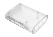
The Raspberry Pi 3 Transparent Injection Case is a protective enclosure designed for the Raspberry Pi 3 Model B and Model B+. It provides a clear, durable case that allows easy viewing of the Raspberry Pi while protecting it from dust, damage, and physical impact. The case is made from high-quality injection-molded plastic, ensuring a precise fit and a sleek, modern look.
Key Features:
- Transparent design for visibility of the Raspberry Pi board
- Injection-molded plastic construction for durability
- Precise cutouts for all ports, connectors, and GPIO pins
- Easy access to SD card slot and USB ports
- Ventilation slots for effective heat dissipation
- Simple snap-together assembly; no tools required
- Includes mounting hardware and rubber feet for stability
Technical Specifications:
- Material: Transparent injection-molded plastic
- Compatibility: Raspberry Pi 3 Model B and Model B+
- Color: Clear/Transparent
- Dimensions: Varies slightly by manufacturer (typically around 90mm x 60mm x 30mm)
- Weight: Varies slightly by manufacturer (typically around 50g)
Applications:
- Protecting Raspberry Pi 3 during use and handling
- Displaying the Raspberry Pi while maintaining access to ports
- Enclosing Raspberry Pi in a professional or educational setting
- Enhancing the aesthetics of Raspberry Pi-based projects
Usage:
- Place the Raspberry Pi 3 into the case, aligning it with the cutouts and mounting points.
- Snap the case parts together to secure the Raspberry Pi in place.
- Ensure all ports and connectors are accessible through the case openings.
- Mount the case using the included rubber feet or screws if required.
Caution:
- Handle the case carefully to avoid scratches or cracks.
- Ensure proper ventilation to prevent overheating of the Raspberry Pi.
- Verify that all connectors and ports are aligned and accessible before use.
Datasheet:
For detailed technical specifications, refer to the Raspberry Pi 3 Transparent Injection Case database.
|
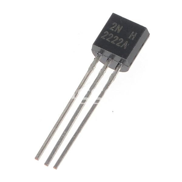
The 2N2222 is a widely used NPN bipolar junction transistor (BJT) known for its versatility in general-purpose switching and amplification applications. It is designed for high-speed switching and low power applications, making it suitable for a wide range of electronic projects. The 2N2222 is commonly used in educational projects, DIY electronics, and professional circuits.
Key Features:
- NPN Bipolar Junction Transistor: Standard NPN configuration for easy integration.
- High-Speed Switching: Suitable for high-speed switching applications.
- Low Power Consumption: Efficient operation with minimal power loss.
- Wide Range of Applications: Versatile for various electronic circuits.
- Robust Design: Reliable performance with a durable construction.
Technical Specifications:
- Transistor Type: NPN
- Collector-Emitter Voltage (Vce): 40V
- Collector-Base Voltage (Vcb): 75V
- Emitter-Base Voltage (Veb): 6V
- Collector Current (Ic): 800mA
- Power Dissipation (Pd): 500mW
- Transition Frequency (ft): 250 MHz
- DC Current Gain (hFE): 35 to 300
- Package Type: TO-18 (metal can), also available in TO-92 (plastic package)
Applications:
- Switching Circuits: Used in switching applications due to its high-speed capabilities.
- Amplification: Suitable for signal amplification in audio and RF circuits.
- Oscillators: Utilized in oscillator circuits for frequency generation.
- Digital Logic Circuits: Used in digital logic and interfacing applications.
- Power Management: Applied in power management circuits for efficient power control.
- DIY Projects: Common in hobbyist and educational electronic projects.
Usage:
- Circuit Design: Integrate the 2N2222 transistor into your circuit design based on its switching or amplification role.
- Biasing: Ensure proper biasing of the transistor for optimal performance.
- Connections: Connect the collector, base, and emitter terminals to the appropriate points in your circuit.
- Testing: Test the circuit to verify the transistor’s functionality and performance.
- Implementation: Use the transistor in your final project, ensuring it operates within the specified limits.
Caution:
- Heat Dissipation: Ensure adequate heat dissipation to prevent overheating.
- Voltage and Current Limits: Operate within the specified voltage and current limits to avoid damage.
- Handling: Handle the transistor with care to avoid electrostatic discharge (ESD) damage.
Datasheet:
For detailed technical specifications, refer to the 2N2222 Transistor Datasheet.
|
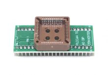
The PLC44 to DIP40 IC Socket Adapter is designed to convert a 44-pin PLCC (Plastic Leaded Chip Carrier) IC package into a 40-pin DIP (Dual Inline Package) socket configuration. This adapter enables the use of PLCC ICs in DIP socket-compatible PCBs and prototyping setups, simplifying integration and testing.
Key Features:
- Convenient Conversion: Adapts a 44-pin PLCC IC for use with a 40-pin DIP socket.
- High-Quality Construction: Built with durable materials to ensure reliable connections and longevity.
- Gold-Plated Contacts: Provides excellent conductivity and corrosion resistance.
- Compact Form Factor: Suitable for use with standard breadboards and PCB mountings.
- Easy Installation: Allows for quick and straightforward installation and removal of ICs.
Technical Specifications:
- Package Type: PLC44 to DIP40
- Pin Pitch (PLCC): 1.27mm
- Pin Pitch (DIP): 2.54mm
- Material: FR4 PCB, Gold-plated contacts
- Dimensions: Varies by model
- Weight: Lightweight design
- Temperature Range: -40°C to +85°C
- Mounting Type: Through-hole
Applications:
- Prototyping: Enables the use of PLCC ICs on DIP-compatible breadboards and prototype boards.
- Development: Facilitates the integration of PLCC devices into DIP-based circuit designs.
- Repair and Replacement: Useful for adapting PLCC ICs in existing DIP-based systems or repairs.
- Educational Use: Ideal for demonstrating the use and conversion of different IC package types.
|
