|
Description |
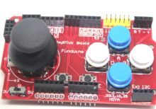
The Joystick Shield V1 is an expansion board designed for Arduino and other compatible microcontroller platforms. It features a joystick, buttons, and connectors that enable easy interfacing for a variety of applications, including gaming, robotics, and interactive projects. The shield provides an intuitive and user-friendly interface for controlling movements and actions in your projects.
Key Features:
- Analog Joystick: Two-axis joystick for precise control of movement.
- Push Buttons: Includes multiple push buttons for additional input options.
- Shield Design: Easily stackable on top of Arduino boards, maintaining a compact form factor.
- Plug and Play: Simple to connect and start using with minimal setup required.
- Versatile Applications: Suitable for gaming controllers, robotic controls, and interactive systems.
Technical Specifications:
- Joystick: 2-axis (X and Y) analog joystick with a push-button function
- Buttons: 5 push buttons (up, down, left, right, select)
- Interface: Connects to Arduino through the standard shield interface
- Operating Voltage: 5V (supplied by the Arduino board)
- Dimensions: Compatible with standard Arduino board dimensions
Applications:
- Gaming Controllers: Create custom gaming controllers for various platforms.
- Robotics: Use the joystick and buttons to control robotic movements and actions.
- Interactive Projects: Develop interactive installations and projects that require user input.
- Prototyping: Ideal for quickly testing and prototyping control interfaces.
Datasheet:
For detailed technical specifications, refer to the Joystick Shield V1 Datasheet.
|
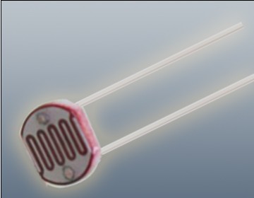
The Photoresistor LDR (Light Dependent Resistor) is a variable resistor whose resistance changes with the light intensity that falls upon it. It is widely used in light sensing applications and projects where detecting light levels is essential. LDRs are cost-effective, easy to use, and suitable for various electronic projects, including light meters, street lights, and other light-sensitive devices.
Key Features:
- Light Sensitivity: Resistance decreases with increasing light intensity
- Simple Interface: Easy to integrate with microcontrollers and analog circuits
- Low Cost: Economical solution for light detection
- Wide Range of Light Detection: Can detect various light levels from low to high intensity
- Compact Size: Fits easily into small projects
Technical Specifications:
- Resistance in Darkness: Typically 1MΩ (depending on specific model)
- Resistance in Bright Light: Typically 10-20kΩ (depending on specific model)
- Spectral Peak: Approximately 540nm (most sensitive to green light)
- Response Time: Rise time ~20ms, fall time ~30ms
- Operating Temperature Range: -30°C to +70°C
- Diameter: Typically 5mm to 10mm (depending on specific model)
Applications:
- Light Meters: Measure light intensity for photography and scientific applications.
- Street Lights: Automatic on/off control based on ambient light levels.
- Alarm Systems: Detect changes in light levels for security purposes.
- Consumer Electronics: Light-sensitive control in devices like clocks and displays.
- Educational Projects: Common component in learning modules for electronics.
Usage:
- Circuit Integration: Connect the LDR in a voltage divider circuit with a fixed resistor to create a variable voltage output based on light intensity.
- Microcontroller Interface: Read the voltage output from the LDR circuit using an analog input pin on a microcontroller.
- Programming: Write code to interpret the analog signal and perform actions based on light levels (e.g., turning on an LED when it gets dark).
- Testing: Calibrate the LDR circuit for the desired light sensitivity by adjusting the fixed resistor value.
Caution:
- Environment: Avoid exposure to extreme temperatures and humidity, which may affect the LDR’s performance.
- Handling: Handle with care to avoid damaging the sensitive surface of the LDR.
Datasheet:
For detailed technical specifications, refer to the Photoresistor LDR Datasheet.
|
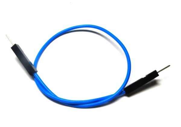
A single male-male jumper wire features male connectors on both ends and is used for making connections between components, breadboards, and other circuit boards. These wires are essential in prototyping and development for creating temporary circuits or testing designs. They allow for easy and flexible connections without the need for soldering.
Key Features:
- Connectors: Male connectors on both ends
- Wire Type: Flexible, insulated wire for easy handling and routing
- Length: Available in various lengths to suit different project needs
- Color-Coded: Available in multiple colors for easy identification and organization
- Durability: Made from high-quality materials for reliable and repeated use
- Compatibility: Suitable for standard 2.54mm (0.1 inch) pitch headers and connectors
Technical Specifications:
- Connector Type: Male-to-male
- Wire Gauge: Typically 28 AWG
- Insulation Material: PVC or similar flexible plastic
- Pitch: 2.54mm (0.1 inch)
- Length Options: Common lengths include 10cm, 20cm, 30cm, and others
- Operating Temperature: Typically -40°C to +80°C
- Current Rating: Usually up to 1A
Applications:
- Prototyping: Ideal for making connections on breadboards and development boards.
- Educational Projects: Used in educational settings to teach electronics and programming concepts.
- DIY Electronics: Suitable for hobbyists and makers working on various electronics projects and experiments.
- Temporary Connections: Useful for creating temporary connections during development and testing.
- Interfacing Components: Facilitates connections between components and modules with male pin headers.
|
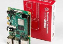
The Raspberry Pi 4 Model B is a versatile and powerful single-board computer, designed for a wide range of applications from DIY projects to professional development. The 1GB RAM version offers sufficient memory for basic tasks and lightweight applications, making it an ideal choice for various computing needs.
Key Features:
- Powerful Processor: Quad-core ARM Cortex-A72 CPU running at 1.5 GHz
- Memory: 1GB LPDDR4 RAM
- Connectivity: Gigabit Ethernet, 2.4GHz and 5GHz Wi-Fi, Bluetooth 5.0
- USB Ports: 2x USB 3.0, 2x USB 2.0
- Video Output: 2x Micro HDMI ports (up to 4K resolution)
- Storage: MicroSD card slot
- GPIO: 40-pin GPIO header for expansion and interfacing
Technical Specifications:
- Processor: Quad-core ARM Cortex-A72, 1.5 GHz
- Memory: 1GB LPDDR4
- Networking: Gigabit Ethernet, Wi-Fi 802.11ac, Bluetooth 5.0
- USB Ports: 2x USB 3.0, 2x USB 2.0
- Video Output: 2x Micro HDMI (supports up to 4K resolution)
- Audio: 3.5mm audio jack
- Storage: MicroSD card slot
- GPIO: 40-pin GPIO header
- Power Supply: 5V DC via USB-C
- Dimensions: 85.6 mm x 56.5 mm
Applications:
- Personal Computers
- Media Centers
- Educational Tools
- Home Automation
- IoT Projects
Usage:
- Connect the Raspberry Pi 4 to a monitor via Micro HDMI cables.
- Insert a microSD card with the desired operating system.
- Connect a USB keyboard and mouse.
- Power the board using a 5V USB-C power supply.
- Follow on-screen instructions to set up the operating system.
Caution:
- Use a compatible 5V USB-C power supply to avoid power issues.
- Handle the board with care to avoid damage to connectors and components.
Datasheet:
For more detailed technical information, refer to the Raspberry Pi 4 Model B Datasheet.
|
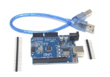
- The Arduino UNO R3 SMD is a popular and versatile microcontroller board based on the ATmega328P microcontroller. The SMD (Surface-Mount Device) version features the ATmega328P microcontroller in an SMD package, offering the same functionality as the traditional UNO R3 but with a more compact design. It is widely used for a variety of projects, from simple experiments to complex prototypes.
Key Features:
- Microcontroller: ATmega328P in SMD package
- Operating Voltage: 5V
- Input Voltage (recommended): 7-12V
- Digital I/O Pins: 14 (of which 6 provide PWM output)
- Analog Input Pins: 6
- Flash Memory: 32 KB (ATmega328P) of which 0.5 KB used by bootloader
- SRAM: 2 KB (ATmega328P)
- EEPROM: 1 KB (ATmega328P)
- Clock Speed: 16 MHz
- USB Connection: Standard USB-B for programming and communication
- Power Jack: 2.1mm center-positive barrel jack
- ICSP Header: For in-circuit programming
- Reset Button: For easy reset of the microcontroller
Technical Specifications:
- Microcontroller: ATmega328P
- Operating Voltage: 5V
- Input Voltage (limits): 6-20V
- Digital I/O Pins: 14 (6 PWM)
- PWM Digital I/O Pins: 6
- Analog Input Pins: 6
- DC Current per I/O Pin: 20 mA
- DC Current for 3.3V Pin: 50 mA
- Flash Memory: 32 KB (ATmega328P) of which 0.5 KB used by bootloader
- SRAM: 2 KB (ATmega328P)
- EEPROM: 1 KB (ATmega328P)
- Clock Speed: 16 MHz
- Length: 68.6 mm
- Width: 53.4 mm
- Weight: 25 g
Applications:
- Educational Projects: Ideal for beginners and students learning electronics and programming.
- Prototyping: Widely used for developing and testing new electronic devices and systems.
- Robotics: Can be used as a controller for various robotics projects.
- Home Automation: Suitable for creating smart home devices and automation systems.
- DIY Projects: Perfect for hobbyists and makers building custom gadgets and interactive installations.
Datasheet:
For detailed technical specifications, refer to the Arduino UNO R3 SMD Datasheet.
|
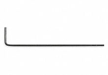
The Allen key, also known as a hex key or hex wrench, is a tool designed for driving screws and bolts with hexagonal sockets. The Size 1.5 mm Allen key is specifically used for fasteners with a 1.5 mm hexagonal socket. This is one of the smallest Allen keys available and is typically used in precision applications where very small fasteners are required.
Key Features:
- Size: 1.5 mm (hexagonal socket size)
- Shape: Commonly L-shaped or T-shaped
- Material: Often made from high-quality steel or chrome vanadium for strength and durability
- Finish: Typically coated with black oxide, chrome plating, or other protective finishes to resist corrosion
- Type: Available in various designs including short or long arm, and sometimes with a ball end for ease of use in tight spaces
Technical Specifications:
- Hexagon Size: 1.5 mm
- Length: Varies by design, usually ranging from 30 mm to 80 mm for short arms, and longer for T-handle or L-handle versions
- Material: Steel, chrome vanadium, or other hardened materials
- Finish: Black oxide, chrome-plated, or other protective coatings
Applications:
- Precision Work: Ideal for tasks involving very small screws and bolts, such as in electronics and small machinery.
- Model Building: Commonly used in assembling and repairing model kits where very small fasteners are used.
- Bicycles: Useful for adjusting components on bicycles that require a small hex size.
- Electronics: Essential for assembling and servicing electronic devices with tiny hex screws.
- Jewelry Making: Used in precision applications where very small screws are common.
Datasheet:
Allen keys generally do not have detailed datasheets, but tool manufacturers or suppliers can provide specifications.
|
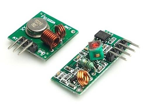
RF (Radio Frequency) Transmitters and Receivers are essential components for wireless communication systems. They are used to transmit and receive radio signals over a distance, making them ideal for remote control, data transmission, and wireless sensor networks. These modules are compact, efficient, and easy to integrate into various electronic projects, providing a reliable solution for wireless communication.
Key Features:
- Wireless Communication: Enables data transmission without physical connections.
- Compact Design: Small size suitable for integration in various projects.
- High Frequency: Operates 433 MHz for clear and stable communication.
- Low Power Consumption: Efficient operation for battery-powered applications.
- Easy Integration: Simple interfacing with microcontrollers and other digital devices.
- Long Range: Capable of transmitting signals over significant distances, depending on the environment and power output.
Technical Specifications:
- Frequency: 433 MHz
- Operating Voltage: 3V to 12V (varies by model)
- Data Rate: Up to 10 kbps (varies by model)
- Range: Up to 100 meters (open space, line of sight)
- Modulation: ASK (Amplitude Shift Keying) / OOK (On-Off Keying)
- Transmitter Power: Typically 10mW (varies by model)
- Receiver Sensitivity: Typically -105 dBm (varies by model)
Applications:
- Remote Controls: Used in remote control systems for various appliances and devices.
- Wireless Data Transmission: Transfer data between microcontrollers without physical connections.
- Home Automation: Control lights, doors, and other home systems wirelessly.
- Wireless Sensor Networks: Collect and transmit sensor data over a wireless network.
- Robotics: Implement wireless communication between robots and control systems.
- Security Systems: Use in alarm systems for transmitting signals from sensors to central units.
Usage:
- Wiring: Connect the transmitter and receiver modules to your microcontroller or control circuit.
- Programming: Write code to send and receive data wirelessly using available libraries for platforms like Arduino.
- Testing: Test the communication range and reliability in your specific environment.
- Integration: Integrate the modules into your final project, ensuring a stable power supply and secure connections.
Caution:
- Interference: Avoid placing near other electronic devices that may cause interference.
- Antenna: Use appropriate antennas to maximize range and signal strength.
- Power Supply: Ensure the modules are supplied with the correct voltage to avoid damage.
- Legal Compliance: Adhere to local regulations regarding RF transmissions and frequencies.
Datasheet:
For detailed technical specifications, refer to the RF Transmitter and Receiver Datasheet.
|
The HC-06 Bluetooth Module is a low-cost, easy-to-use Bluetooth SPP (Serial Port Protocol) module designed for transparent wireless serial communication. It enables devices to communicate wirelessly over a short range, making it ideal for use in wireless communication projects, home automation, and other embedded systems.
Key Features:
- Bluetooth V2.0+EDR (Enhanced Data Rate) compliant
- Serial port Bluetooth module for wireless communication
- Easy to interface with microcontrollers using UART
- Default baud rate of 9600 bps (configurable)
- Supports both Master and Slave modes
- Compact design with built-in antenna
- Low power consumption
- LED indicator for connection status
Technical Specifications:
- Bluetooth Standard: Bluetooth V2.0+EDR
- Frequency Range: 2.4 GHz ISM band
- Operating Voltage: 3.3V to 5V
- Operating Current: 30 mA (typical)
- Communication Range: Up to 10 meters (unobstructed)
- Default Baud Rate: 9600 bps (configurable from 4800 bps to 115200 bps)
- Data Bits: 8
- Stop Bits: 1
- Parity: None
- UART Interface: TX, RX, VCC, GND
- Dimensions: Approximately 28mm x 15mm x 2.5mm
- Weight: 2g
Applications:
- Wireless serial communication
- Home automation systems
- Remote control systems
- Data acquisition systems
- Wireless sensors
- Robotics and DIY projects
- Wireless data logging
Usage:
- Connection:
- Connect the VCC pin to a 3.3V to 5V power supply.
- Connect the GND pin to ground.
- Connect the TX pin of the module to the RX pin of the microcontroller.
- Connect the RX pin of the module to the TX pin of the microcontroller.
- Pairing:
- Power on the module; it will enter pairing mode, indicated by a flashing LED.
- Search for the module using a Bluetooth-enabled device (e.g., smartphone, tablet, PC) and pair with it. The default pairing code is usually “1234” or “0000.”
- Once paired, the LED will stop flashing and remain on, indicating a successful connection.
- Communication:
- Use serial communication commands to send and receive data between the microcontroller and the paired device.
- Configure the module’s settings (e.g., baud rate) if necessary using AT commands.
Caution:
- Ensure proper voltage levels to avoid damaging the module.
- Handle the module carefully to avoid static discharge and physical damage.
- Avoid placing the module near metal objects to maintain optimal signal strength.
Datasheet:
For detailed technical specifications, refer to the HC-06 Bluetooth Module Datasheet.
|
