- You have no items in your shopping cart
- Subtotal: ₦0.00

hi guys, welcome to the weekend DIY tutorials. Each weekend will feature cool tutorials that will teach you how to build different projects ranging from home automation to several other cool things and it will span the use of random microcontrollers and development platforms including, the popular arduino, Raspberry pi, Esp-boards, Particle photon, TI launchpad among others.
For this week we will be building a weighing scale. Have you ever wanted to know the weight of something? How about knowing the change in weight over time? Do you want your project to sense the presence of something by measuring strain or a load on some surface. If so, you’re in the right place.
The weighing scale forms the basis for several devices we come in contact with in our everyday life from weighing scales used in trading stores to the BMI machines in health. An Interesting follow up to this project will be a DIY home inventory management system to ensure you stay up to date as far as the amount of a particular food stuff left in you store for instance is concerned.
For this tutorial we will be working with the following components below;
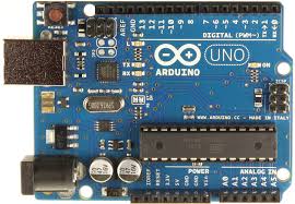
1. Arduino Uno (any other member of the family works)
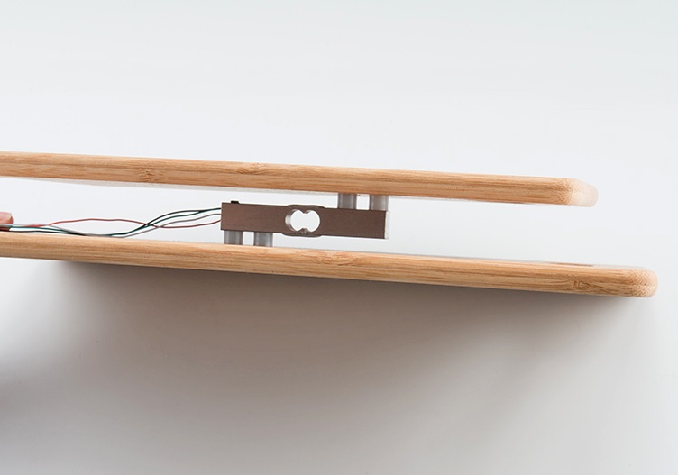
2. Load Cell
3. Hx711 Amplifier
4. 1602 LCD
5. Resistor (220 ohms)
7. A wooden Surface
Understanding the Load cell
Its probably nice to take a look at the Load cell which is almost the most important piece in this puzzle.
A load cell is a sensor or a transducer that converts a load or force acting on it into an electronic signal. This electronic signal can be a voltage change, current change or frequency change depending on the type of load cell and circuitry used. There are many different kinds of load cells, but for this tutorial we will be working with the Strain gauge load cells.
The strain gauge load cell is a mechanical sensing element of which senses the applied force by the deformation of a (or several) strain gauge(s) on the element.
The Load cell is setup in such a way that the torque applied to the bar in such a way that the four strain gauges on the cell will measure the bending distortion, two measuring compression and two tension. These four strain gauges are set up in a wheatstone bridge formation,so it is easy to accurately measure the small changes in resistance from the strain gauges.
The millivolt output of the strain guage is not large enough to be measured accurately by an average voltmeter or DMM. One needs to amplify the signal carefully to obtain a signal large enough to be imputed to a Micro-controller that has a Analog to Digital Converter that is where the hx711 amplifier comes in.

Schematics
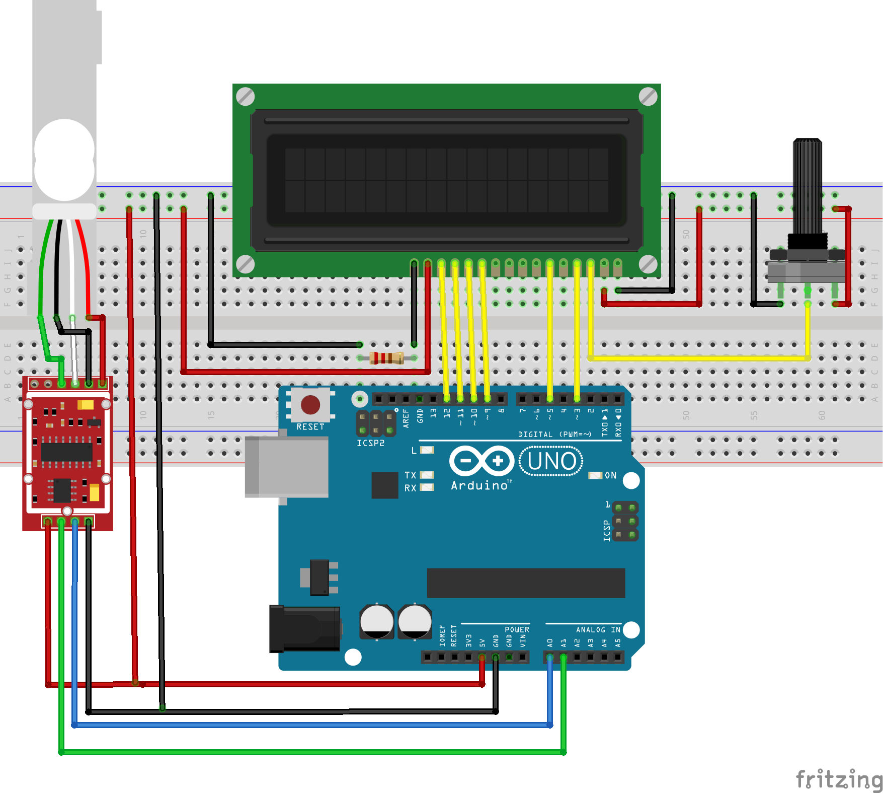
now that we have gotten explanations on the load cell out of the way, lets connect the components.

Depending on the kind of load cell you are working with the black E- wire may actually have to be connected to E+ of your Hx711 amplifier its thus very important to check the data sheet of your load cell to be sure of how it connects.
Your final setup should probably look like the Image below.

Code
for this project we will need the Hx711 master arduino library which can be gotten from here, download and install the library. Our tasks is simply to measure the wait and display it on the LCD screen.
you can follow the Hx711 library on github to better understand the capabilities and ow well to use the library.
Below is the code, Just copy and paste into your arduino IDE after installing the Hx711 arduino library.
#include #include "HX711.h"
// HX711.DOUT – pin #A1
// HX711.PD_SCK – pin #A0
LiquidCrystal lcd(12, 11, 5, 4, 3, 2);
HX711 scale(A1, A0); // parameter “gain” is ommited; the default value 128 is used by the library
void setup() {
Serial.begin(38400);
lcd.begin(16, 2);
lcd.print(“weight Measurement”);
delay(1000);
lcd.clear();
lcd.print(“setting up”);
Serial.println(“Weight Measurement”);
Serial.println(“Before setting up the scale:”);
Serial.print(“read: \t\t”);
Serial.println(scale.read()); // print a raw reading from the ADC
Serial.print(“read average: \t\t”);
Serial.println(scale.read_average(20)); // print the average of 20 readings from the ADC
Serial.print(“get value: \t\t”);
Serial.println(scale.get_value(5)); // print the average of 5 readings from the ADC minus the tare weight (not set yet)
Serial.print(“get units: \t\t”);
Serial.println(scale.get_units(5), 1); // print the average of 5 readings from the ADC minus tare weight (not set) divided
// by the SCALE parameter (not set yet)
scale.set_scale(2280.f); // this value is obtained by calibrating the scale with known weights; see the README for details
scale.tare(); // reset the scale to 0
Serial.println(“After setting up the scale:”);
Serial.print(“read: \t\t”);
Serial.println(scale.read()); // print a raw reading from the ADC
Serial.print(“read average: \t\t”);
Serial.println(scale.read_average(20)); // print the average of 20 readings from the ADC
Serial.print(“get value: \t\t”);
Serial.println(scale.get_value(5)); // print the average of 5 readings from the ADC minus the tare weight, set with tare()
Serial.print(“get units: \t\t”);
Serial.println(scale.get_units(5), 1); // print the average of 5 readings from the ADC minus tare weight, divided
// by the SCALE parameter set with set_scale
Serial.println(“Readings:”);
}
void loop() {
Serial.print(“one reading:\t”);
Serial.print(scale.get_units(), 1);
Serial.print(“\t| average:\t”);
Serial.println(scale.get_units(10), 1);
lcd.clear();
lcd.setCursor(1,1);
lcd.print(scale.get_units(10), 1);
scale.power_down(); // put the ADC in sleep mode
delay(5000);
scale.power_up();
}
It is important to calibrate the scale as described in the code to ensure optimum performance. To allow for easy calibration, the code uses a lot of serial print which will guide you through the process of calibration.
that’s it guys as always, Let me know if you have any questions.
Have a great weekend!


