|
Description |
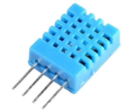
The DHT11 is a basic, ultra-low-cost digital temperature and humidity sensor. It uses a capacitive humidity sensor and a thermistor to measure the surrounding air and outputs a digital signal on the data pin. It’s simple to use but requires careful timing to grab data. It’s perfect for DIY projects, weather stations, and other applications where accurate and reliable temperature and humidity readings are needed.
Key Features:
- Temperature Range: 0-50°C with ±2°C accuracy
- Humidity Range: 20-80% RH with ±5% RH accuracy
- Low Power Consumption: Efficient for battery-operated applications
- Single Wire Digital Interface: Easy to interface with microcontrollers
- Pre-calibrated: No need for additional calibration
- Compact Size: Suitable for compact projects and devices
Technical Specifications:
- Temperature Range: 0-50°C (32-122°F)
- Humidity Range: 20-80% RH
- Temperature Accuracy: ±2°C
- Humidity Accuracy: ±5% RH
- Operating Voltage: 3.3V to 5.5V
- Max Current: 2.5mA
- Output: Digital signal via 1-wire protocol
- Dimensions: 15.5mm x 12mm x 5.5mm
Applications:
- Weather Stations: Monitor and log temperature and humidity levels.
- Home Automation: Control HVAC systems based on environmental conditions.
- Greenhouses: Maintain optimal growing conditions for plants.
- DIY Projects: Perfect for hobbyists building custom sensors and gadgets.
- Data Loggers: Record environmental data over time for analysis.
- Educational Projects: Teach students about sensors and data acquisition.
Usage:
- Wiring: Connect the VCC pin to 3.3V or 5V, GND to ground, and the DATA pin to a digital input on your microcontroller.
- Library Integration: Use libraries available for platforms like Arduino or Raspberry Pi to simplify reading data from the sensor.
- Coding: Write code to initialize the sensor and read temperature and humidity data.
- Data Processing: Process and use the sensor data in your application as needed, such as displaying it on an LCD or sending it to a web server.
Caution:
- Power Supply: Ensure the sensor is supplied with the correct voltage to avoid damage.
- Environmental Conditions: Keep the sensor in a dust-free, non-condensing environment for accurate readings.
- Wiring Length: Minimize the length of wiring between the sensor and the microcontroller to maintain signal integrity.
Datasheet:
For detailed technical specifications, refer to the DHT11 Datasheet.
|
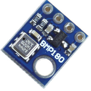
The BMP180 is a high-precision digital barometer and altitude sensor from Bosch, designed to measure atmospheric pressure and temperature. It is commonly used in applications requiring accurate altitude measurement and weather monitoring. The BMP180 provides reliable data for various applications including GPS, weather stations, and altitude tracking in wearable devices.
Key Features:
- Accurate barometric pressure and temperature measurement
- Digital interface with I²C or SPI communication
- High resolution with 0.03 hPa pressure measurement accuracy
- Compact and low-power design
- Built-in calibration for precise readings
- Wide operating temperature range
Technical Specifications:
- Sensor Type: Barometric Pressure and Temperature Sensor
- Communication Protocol: I²C (default), SPI (optional)
- Pressure Range: 300 hPa to 1100 hPa
- Pressure Accuracy: ±1 hPa (typical)
- Temperature Range: -40°C to +85°C
- Temperature Accuracy: ±1°C
- Resolution: 0.03 hPa for pressure
- Operating Voltage: 1.8V to 3.6V
- Current Consumption: 3µA (typical in sleep mode), 10µA (typical in measurement mode)
- Package Type: LGA-8 (Leadless Grid Array)
Applications:
- Altitude and weather tracking
- GPS altitude calibration
- Pressure-based data logging
- Environmental monitoring
- Wearable devices and consumer electronics
Usage:
- Connect the BMP180 sensor to your microcontroller or development board using I²C or SPI interface.
- Power the sensor with a voltage within the operating range (1.8V to 3.6V).
- Use the appropriate library or driver for the I²C or SPI protocol to interface with the sensor.
- Retrieve and process pressure and temperature data according to your application needs.
Caution:
- Ensure proper voltage supply to avoid damage to the sensor.
- Handle the sensor carefully to prevent mechanical damage or contamination.
- Verify correct wiring and communication protocol settings for accurate readings.
Datasheet:
For detailed technical specifications, refer to the BMP180 Datasheet.
|
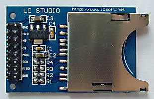
The SD Card Module is a compact and efficient solution for adding storage capabilities to your microcontroller or development board projects. It allows you to read from and write to SD cards, making it ideal for data logging, file storage, and other applications requiring large amounts of memory. The module supports various SD card formats and interfaces seamlessly with popular microcontrollers like Arduino, Raspberry Pi, and others.
Key Features:
- Storage: Supports SD, SDHC, and MicroSD (with adapter) cards
- Interface: SPI interface for easy integration
- Voltage Compatibility: Operates at 3.3V and 5V
- Onboard 3.3V Regulator: Ensures stable operation
- Card Detection: Built-in card detection switch
- Compact Design: Small footprint for easy incorporation into projects
- File System: Compatible with FAT16 and FAT32 file systems
Technical Specifications:
- Supported Cards: SD, SDHC, MicroSD (with adapter)
- Operating Voltage: 3.3V/5V
- Interface: SPI
- Current Consumption: < 100mA
- File System: FAT16, FAT32
- Dimensions: 42mm x 24mm x 12mm
Applications:
- Data Logging: Store sensor data and logs in embedded systems.
- File Storage: Save files for multimedia applications and projects.
- Firmware Updates: Load new firmware from the SD card for microcontrollers.
- DIY Projects: Perfect for hobbyists needing additional storage.
- Educational Projects: Commonly used in learning modules for data storage and retrieval.
Usage:
- Wiring: Connect the SD card module to your microcontroller using the SPI interface (CS, MOSI, MISO, SCK, VCC, GND).
- Power Supply: Ensure the module is powered with 3.3V or 5V, as required.
- Card Insertion: Insert a formatted SD card into the module.
- Programming: Use libraries (e.g., SD library for Arduino) to initialize the SD card and read/write data.
- Data Handling: Store or retrieve data files from the SD card as needed by your application.
Caution:
- Voltage Levels: Ensure proper voltage levels to avoid damaging the module.
- Handling SD Cards: Handle SD cards with care to prevent data loss or corruption.
Datasheet:
For detailed technical specifications, refer to the SD Card Module Datasheet.
|
|
The Raspberry Pi 3.5 Inches Resistive Touch Screen is a compact display module designed specifically for use with Raspberry Pi boards. This touch screen offers a user-friendly interface for various applications, allowing you to interact directly with your Raspberry Pi projects. It features a resistive touch panel, making it suitable for applications that require precise touch input.
Key Features:
- Screen Size: 3.5 inches
- Display Type: TFT LCD
- Resolution: 320 x 480 pixels
- Touch Type: Resistive touch panel
- Interface: SPI (Serial Peripheral Interface)
- Compatibility: Compatible with Raspberry Pi models such as Raspberry Pi 4, 3, 2, and Zero
Technical Specifications:
- Screen Size: 3.5 inches
- Display Resolution: 320 x 480 pixels
- Touch Panel: Resistive
- Interface: SPI
- Operating Voltage: 3.3V/5V (powered through Raspberry Pi GPIO)
- Dimensions: Approximately 85mm x 55mm x 30mm
- Viewing Angle: Wide viewing angle
- Backlight: LED backlight for enhanced visibility
Applications:
- Portable Raspberry Pi projects
- DIY handheld devices
- Control interfaces for home automation
- Interactive displays for education and prototyping
- Gaming consoles and entertainment systems
Usage:
- Connect the 3.5-inch touch screen to the GPIO pins of your Raspberry Pi board.
- Install the necessary drivers and configure the Raspberry Pi for the touch screen.
- Calibrate the touch panel if required to ensure accurate touch input.
- Use the touch screen to interact with your Raspberry Pi applications, projects, or operating system.
Caution:
- Handle the touch screen carefully to avoid damaging the display or touch panel.
- Ensure the GPIO pins are correctly connected to avoid short circuits or incorrect operation.
- Follow the manufacturer’s guidelines for driver installation and configuration.
Datasheet:
For detailed technical specifications, refer to the Raspberry Pi 3.5 Inches Resistive Touch Screen Datasheet.
|
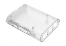
The Raspberry Pi 3 Transparent Injection Case is a protective enclosure designed for the Raspberry Pi 3 Model B and Model B+. It provides a clear, durable case that allows easy viewing of the Raspberry Pi while protecting it from dust, damage, and physical impact. The case is made from high-quality injection-molded plastic, ensuring a precise fit and a sleek, modern look.
Key Features:
- Transparent design for visibility of the Raspberry Pi board
- Injection-molded plastic construction for durability
- Precise cutouts for all ports, connectors, and GPIO pins
- Easy access to SD card slot and USB ports
- Ventilation slots for effective heat dissipation
- Simple snap-together assembly; no tools required
- Includes mounting hardware and rubber feet for stability
Technical Specifications:
- Material: Transparent injection-molded plastic
- Compatibility: Raspberry Pi 3 Model B and Model B+
- Color: Clear/Transparent
- Dimensions: Varies slightly by manufacturer (typically around 90mm x 60mm x 30mm)
- Weight: Varies slightly by manufacturer (typically around 50g)
Applications:
- Protecting Raspberry Pi 3 during use and handling
- Displaying the Raspberry Pi while maintaining access to ports
- Enclosing Raspberry Pi in a professional or educational setting
- Enhancing the aesthetics of Raspberry Pi-based projects
Usage:
- Place the Raspberry Pi 3 into the case, aligning it with the cutouts and mounting points.
- Snap the case parts together to secure the Raspberry Pi in place.
- Ensure all ports and connectors are accessible through the case openings.
- Mount the case using the included rubber feet or screws if required.
Caution:
- Handle the case carefully to avoid scratches or cracks.
- Ensure proper ventilation to prevent overheating of the Raspberry Pi.
- Verify that all connectors and ports are aligned and accessible before use.
Datasheet:
For detailed technical specifications, refer to the Raspberry Pi 3 Transparent Injection Case database.
|
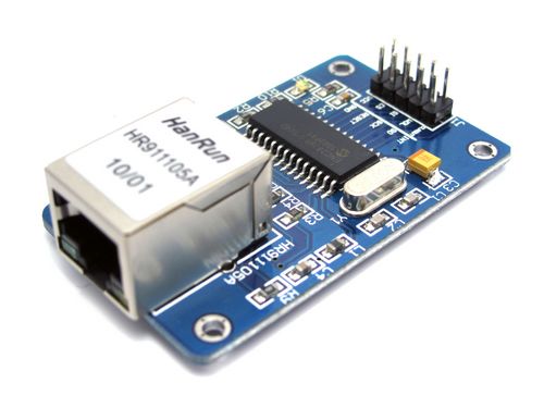
The ENC28J60 Ethernet Network Board Module is a compact and efficient solution for adding Ethernet connectivity to microcontroller-based projects. It features the ENC28J60 Ethernet controller from Microchip Technology, which is a standalone Ethernet controller with an SPI interface. This module is ideal for embedded systems that require network communication capabilities, such as IoT devices, web servers, and home automation systems.
Key Features:
- ENC28J60 Ethernet controller chip
- Supports 10Mbps data rate
- SPI interface for easy integration with microcontrollers
- Built-in MAC and PHY layer
- Low power consumption
- Compact design with RJ45 connector and status LEDs
- Compatible with various microcontroller platforms
Technical Specifications:
- Ethernet Controller: ENC28J60
- Data Rate: 10Mbps
- Interface: SPI (Serial Peripheral Interface)
- Operating Voltage: 3.3V
- Current Consumption: Typically 180mA
- Connector Type: RJ45 Ethernet connector
- Dimensions: Typically 48mm x 24mm x 15mm (varies slightly by manufacturer)
- Operating Temperature Range: -40°C to +85°C
Applications:
- IoT (Internet of Things) devices
- Home automation systems
- Web servers and clients
- Networked sensors and data loggers
- Remote monitoring and control systems
- Embedded systems requiring network connectivity
Usage:
- Connect the ENC28J60 module to your microcontroller or development board using the SPI interface (CS, SCK, MISO, MOSI) and power supply (3.3V, GND).
- Use the appropriate library or driver for your microcontroller platform to initialize and configure the ENC28J60 for network communication.
- Connect the module to an Ethernet network using the RJ45 connector.
- Implement network communication protocols and functions in your application code to interact with other devices or servers over the network.
- Monitor the status LEDs on the module for network activity and connection status.
Caution:
- Ensure the power supply voltage is 3.3V to avoid damaging the module.
- Verify SPI connections and configuration settings for proper communication with the microcontroller.
- Handle the module carefully to avoid damage to the electronic components and connectors.
Datasheet:
For detailed technical specifications, refer to the ENC28J60 Datasheet.
|
The Creality CR-6SE is a high-precision 3D printer designed for users seeking reliable, professional-quality prints. Known for its ease of use and innovative features, the CR-6SE offers an enhanced printing experience with a focus on accuracy, stability, and user convenience. Ideal for hobbyists, educators, and professionals, this 3D printer delivers excellent performance for a variety of projects, from prototypes to complex models.
Key Features:
- High Precision Printing: Delivers detailed and accurate prints with a layer resolution of 0.1 mm.
- Auto-Leveling System: Features an advanced leveling-free system for hassle-free setup.
- Silent Operation: Equipped with a silent motherboard and TMC2209 drivers for quiet printing.
- Sturdy Construction: Built with a robust aluminum frame for stability and durability.
- Modular Design: Easy to assemble and maintain with a modular design.
- Resume Printing Function: Capable of resuming printing after power outages or interruptions.
- Touch Screen Interface: 4.3-inch color touch screen for an intuitive user interface.
- Dual Z-Axis: Provides improved accuracy and stability for the Z-axis movement.
Technical Specifications:
- Build Volume: 235 x 235 x 250 mm
- Layer Resolution: 0.1 mm
- Printing Speed: Up to 100 mm/s
- Nozzle Diameter: Standard 0.4 mm (interchangeable)
- Filament Compatibility: PLA, ABS, TPU, PETG, and other 1.75 mm filaments
- Extruder Type: Single Bowden extruder
- Print Bed: Carborundum glass platform for better adhesion and easy removal of prints
- Connectivity: USB, SD card
- Operating Temperature: Nozzle: Up to 260°C, Bed: Up to 110°C
- Power Supply: Meanwell 24V 350W
Applications:
- Prototyping: Ideal for creating accurate and detailed prototypes.
- Education: Useful for educational purposes in schools and universities.
- Art and Design: Perfect for artists and designers creating intricate models.
- DIY Projects: Suitable for hobbyists and makers working on custom projects.
- Manufacturing: Can be used for small-scale manufacturing and production of parts.
Usage:
- Assembly: Follow the provided instructions to assemble the 3D printer.
- Leveling: Use the auto-leveling system to ensure the print bed is properly leveled.
- Loading Filament: Load the desired filament into the extruder.
- Printing: Upload the 3D model via USB or SD card and start the print job using the touch screen interface.
- Post-Processing: Remove the finished print from the bed and perform any necessary post-processing.
Caution:
- Safety: Always operate the printer in a well-ventilated area.
- Temperature: Handle heated components with care to avoid burns.
- Maintenance: Regularly clean and maintain the printer for optimal performance.
Datasheet:
For detailed technical specifications, refer to the Creality CR-6SE Datasheet.
|
Description:
The USB DC-DC Buck Boost Module with Seven Segment Display is a versatile power management module designed to provide adjustable output voltage from a USB power source. It combines a DC-DC buck-boost converter with a seven-segment display for real-time monitoring of the output voltage.
Key Features:
- Buck-Boost Converter: Capable of both stepping up and stepping down the input voltage to achieve a stable output.
- Adjustable Output Voltage: Allows precise adjustment of the output voltage using onboard controls.
- Seven-Segment Display: Provides real-time voltage readings for easy monitoring and adjustment.
- USB Powered: Operates from a standard USB power source (5V DC).
- Compact Design: Easy to integrate into various applications due to its small size.
Technical Specifications:
- Input Voltage: USB 5V DC
- Output Voltage Range: Typically adjustable from 1.5V to 12V DC
- Output Current: Up to 3A
- Display: Seven-segment LED for voltage readout
- Dimensions: Compact size suitable for various applications
Applications:
- Power Supply: Provides adjustable voltage for powering different electronic devices.
- Portable Projects: Ideal for battery-powered or USB-powered projects requiring voltage regulation.
- Educational Kits: Useful for learning about power conversion and electronics.
- DIY Electronics: Suitable for custom electronic projects needing adjustable power supply.
|
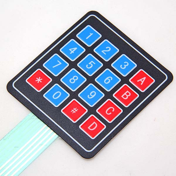
The 4×4 Matrix Keypad is a user-friendly input device consisting of 16 keys arranged in a 4×4 matrix. It is widely used in embedded systems, microcontroller projects, and DIY electronics for user input. Each key press is detected by scanning the matrix, allowing for efficient and reliable data entry. The keypad is compact, durable, and easy to integrate into various projects.
Key Features:
- Key Configuration: 4 rows and 4 columns, totaling 16 keys
- Interface: Matrix scanning
- Key Labels: Numeric and function keys (0-9, A-D, *, #)
- Compact Design: Suitable for handheld devices and small projects
- Durable: Made from high-quality materials for long-lasting use
- Flexible: Can be connected to any microcontroller or development board
- Low Power Consumption: Efficient operation with minimal power usage
Technical Specifications:
- Number of Keys: 16 (4×4 matrix)
- Operating Voltage: 3.3V to 5V
- Current Consumption: < 10mA
- Contact Resistance: ≤ 200 ohms
- Insulation Resistance: ≥ 100M ohms (at 250V DC)
- Operating Temperature Range: -20°C to +60°C
- Keypad Dimensions: 69mm x 69mm x 1.8mm
- Connection Type: 8-pin header
Applications:
- Embedded Systems: User input for microcontroller-based projects.
- DIY Electronics: Ideal for hobbyists and makers creating custom projects.
- Access Control: Use in security systems for code entry.
- Consumer Electronics: Keypad input for appliances and gadgets.
- Educational Projects: Commonly used in educational kits and learning modules.
Usage:
- Wiring: Connect the 8-pin header to the microcontroller or development board, ensuring correct row and column connections.
- Programming: Use libraries (e.g., Keypad library for Arduino) to read key presses and handle input.
- Integration: Incorporate the keypad into your project for reliable user input.
- Testing: Verify the functionality by pressing keys and checking the output.
Caution:
- Proper Connection: Ensure the keypad is connected correctly to avoid malfunction.
- Voltage Levels: Operate within the specified voltage range to prevent damage.
Datasheet:
For detailed technical specifications, refer to the 4×4 Matrix Keypad Datasheet.
|
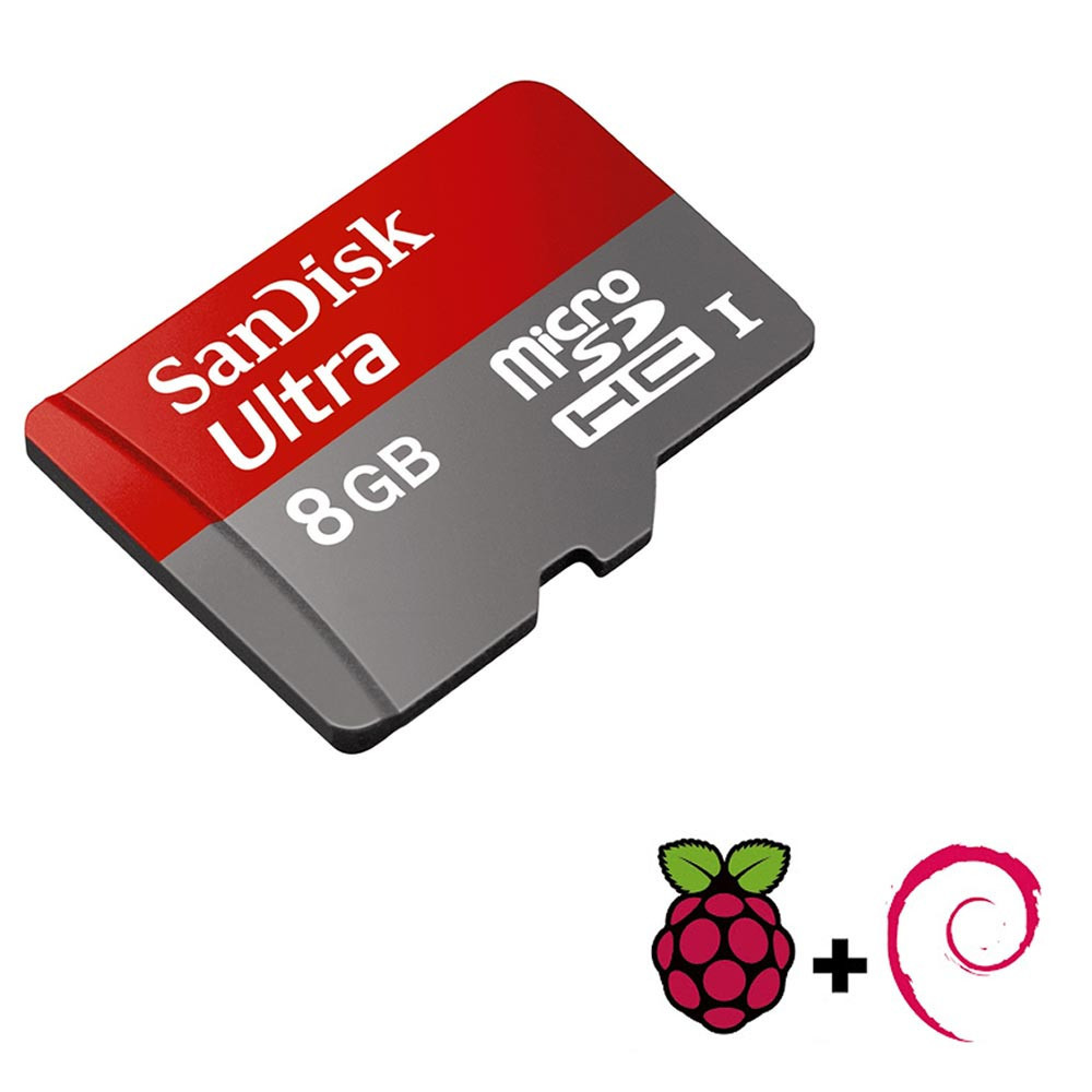
The Raspberry Pi 8GB SD card is a high-performance memory card designed for use with Raspberry Pi computers. It provides the necessary storage for the operating system, applications, and data. The card typically comes pre-loaded with a Raspberry Pi-compatible OS, making it ready for use right out of the box.
Key Features:
- Storage Capacity: 8GB
- Form Factor: SD Card (usually microSD)
- Speed Class: UHS-I (Ultra High Speed) or Class 10 for fast read and write speeds
- Pre-installed OS: Often pre-loaded with Raspberry Pi OS (formerly Raspbian) or other compatible operating systems
- Compatibility: Designed for use with Raspberry Pi models that support microSD cards
Technical Specifications:
- Storage Capacity: 8GB
- Card Type: microSD or SD (depending on the specific model)
- Speed Class: Class 10 or UHS-I (depending on the card)
- Read Speed: Typically up to 80MB/s (varies by manufacturer)
- Write Speed: Typically up to 20MB/s (varies by manufacturer)
- Operating Temperature Range: -25°C to +85°C (varies by manufacturer)
- File System: FAT32 or exFAT (usually formatted for compatibility with Raspberry Pi)
Applications:
- Operating System Storage: Primary storage for Raspberry Pi operating systems and software
- Data Storage: Store files, projects, and applications for Raspberry Pi
- Backup and Recovery: Useful for creating backups of Raspberry Pi setups and data
Usage:
- Insert into Raspberry Pi: Insert the microSD card into the microSD card slot on the Raspberry Pi.
- Boot Up: Power on the Raspberry Pi. If the card is pre-loaded with an OS, the device should boot up automatically.
- Setup: Follow on-screen instructions to configure the operating system and perform initial setup.
- Transfer Data: Use the card for data storage, program installation, and other tasks as needed.
Caution:
- Data Backup: Regularly back up important data to avoid loss due to card failure or corruption.
- Avoid Physical Damage: Handle the card carefully to avoid physical damage or data corruption.
- Proper Formatting: Ensure the card is properly formatted before use if not pre-loaded.
|
The Raspberry Pi 5 (8GB RAM) is the latest iteration in the Raspberry Pi series, featuring significant performance improvements and expanded memory to handle more demanding applications. With a powerful quad-core processor, enhanced GPU, and versatile connectivity options, this compact single-board computer is ideal for a wide range of projects and applications.
Key Features:
- 8GB RAM: Ample memory for complex tasks and multitasking
- Quad-Core Processor: Enhanced processing power for improved performance
- Enhanced GPU: Supports 4K video output and better graphics performance
- Multiple Connectivity Options: USB 3.0 ports, Gigabit Ethernet, Bluetooth 5.0, and Wi-Fi
- Expandable Storage: MicroSD card slot and USB boot capability
- GPIO Pins: 40-pin GPIO header for hardware projects
Technical Specifications:
- Processor: Quad-core ARM Cortex-A72, 1.8GHz
- Memory: 8GB LPDDR4 RAM
- Graphics: Broadcom VideoCore VI, supports dual 4K displays
- Storage: MicroSD card slot, USB boot support
- Connectivity:
- 2 x USB 3.0 ports
- 2 x USB 2.0 ports
- Gigabit Ethernet
- Dual-band 2.4/5.0 GHz IEEE 802.11ac wireless
- Bluetooth 5.0
- Video Output: 2 x micro HDMI ports (supports up to 4K resolution)
- Audio Output: 3.5mm audio jack, HDMI
- Power Supply: 5V/3A USB-C power input
- GPIO: 40-pin GPIO header
- Operating System: Compatible with Raspberry Pi OS and various Linux distributions
Applications:
- Home automation
- Media centers and streaming devices
- IoT projects
- Educational tools for learning programming and electronics
- Personal computing and office tasks
- Robotics and AI projects
Usage:
- Insert a pre-loaded microSD card with the operating system into the microSD card slot.
- Connect peripherals such as a keyboard, mouse, and monitor.
- Plug in the power supply to the USB-C power input.
- Set up and configure your Raspberry Pi 5 as needed.
Caution:
- Use a high-quality power supply to ensure stable operation.
- Handle the board with care to avoid static damage to components.
Datasheet:
For more detailed technical information, refer to the Raspberry Pi 5 (8GB RAM) Datasheet.
|
The Raspberry Pi HDMI to VGA Converter is a compact adapter designed to enable the connection of a Raspberry Pi to a VGA display or monitor. This converter transforms the digital HDMI output from the Raspberry Pi into an analog VGA signal, allowing for compatibility with older monitors and projectors that support VGA input. It is an essential accessory for users who need to interface their Raspberry Pi with VGA-equipped display devices.
Key Features:
- HDMI to VGA Conversion: Converts HDMI digital signal to VGA analog signal
- Resolution Support: Supports common VGA resolutions up to 1080p
- Power Supply: Powered through the HDMI connection (no additional power required)
- Compact Design: Small and lightweight for easy integration
- Plug-and-Play: No additional drivers or software required
- Audio Support: Some models may include a separate audio output for connecting external speakers
Technical Specifications:
- Input: HDMI Type A (female)
- Output: VGA (15-pin D-Sub, female)
- Resolution Support: Up to 1920×1080 (1080p)
- Power Supply: Powered through HDMI connection (requires sufficient HDMI power)
- Dimensions: Typically compact, around 50mm x 30mm x 20mm
- Weight: Approximately 50g
Applications:
- Connecting Raspberry Pi to VGA monitors or projectors
- Using older VGA display equipment with modern HDMI devices
- Educational and DIY projects requiring VGA display output
- Retro computing and display setups
Usage:
- Connect the HDMI end of the converter to the HDMI output of the Raspberry Pi.
- Connect the VGA end of the converter to the VGA input of the monitor or projector.
- Optionally, connect an external audio cable if the converter provides a separate audio output.
- Power on the Raspberry Pi and the display device to start using the setup.
Caution:
- Ensure the HDMI and VGA connections are secure to prevent signal loss or display issues.
- Verify that the VGA display supports the resolution output by the Raspberry Pi.
- Check the power requirements of the HDMI connection to ensure proper operation.
Datasheet:
For detailed technical specifications, refer to the Raspberry Pi HDMI to VGA Converter Datasheet.
|
The MCP4725 I2C DAC Breakout Board is a compact and versatile module designed to provide digital-to-analog conversion with high precision. Based on the MCP4725 DAC chip, this board allows you to convert digital values into an analog output voltage, making it ideal for various applications such as signal generation, control systems, and data acquisition.
Key Features:
- I2C Interface: Utilizes the I2C communication protocol for easy integration with microcontrollers and other digital systems.
- 12-bit Resolution: Provides 12-bit resolution for accurate and fine-grained analog output.
- Adjustable Output Voltage: Capable of generating a wide range of output voltages based on the supplied reference voltage.
- Built-in EEPROM: Includes EEPROM memory for storing DAC settings and configurations.
- Compact Design: Small form factor suitable for integration into various projects and devices.
Technical Specifications:
- DAC Type: Digital-to-Analog Converter (DAC)
- Resolution: 12 bits
- Communication Interface: I2C
- Output Voltage Range: Dependent on the reference voltage (typically 0V to VDD)
- Reference Voltage: VDD (Supply Voltage)
- Power Supply: Typically 2.7V to 5.5V
- Operating Temperature Range: -40°C to +125°C
- Package Type: Varies by specific board design (e.g., SMD components)
Applications:
- Signal Generation: Used in applications requiring precise analog signal generation.
- Control Systems: Suitable for use in control systems where analog outputs are needed.
- Data Acquisition: Ideal for converting digital data into analog signals for measurement and monitoring.
- Prototyping: Useful in prototyping and development projects that require DAC functionality.
Datasheet:
For detailed technical specifications, refer to the MCP4725 Datasheet.
|
Description:
The MCU FT232H to JTAG UART FIFO SPI I2C Module is a versatile interface module that uses the FT232H chip to provide a bridge between various communication protocols and your microcontroller or development board. It supports multiple interfaces including JTAG, UART, FIFO, SPI, and I2C, making it a flexible solution for interfacing with different types of peripherals and systems.
Key Features:
- FT232H Chip: Utilizes the FTDI FT232H for high-performance USB to serial conversion.
- Multiple Interfaces: Supports JTAG, UART, FIFO, SPI, and I2C communication protocols.
- High-Speed Operation: Capable of high-speed data transfer for efficient communication.
- Easy Integration: Designed for straightforward integration with development boards and microcontrollers.
- USB Connectivity: Provides USB interface for easy connection to computers and other USB-enabled devices.
- Flexible Configuration: Configurable to meet various interfacing needs and protocols.
Technical Specifications:
- Interface Chip: FTDI FT232H
- Supported Protocols: JTAG, UART, FIFO, SPI, I2C
- USB Interface: USB 2.0
- Operating Voltage: 3.3V or 5V (depending on configuration)
- Maximum Data Rate: Up to 12 Mbps (depending on protocol)
- Connector Types: Various connectors depending on the module design
- Dimensions: Compact size suitable for integration into different setups
- Weight: Lightweight for minimal impact on connected systems
Applications:
- Development Boards: Used for expanding the communication capabilities of microcontroller development boards.
- Interface Bridging: Acts as a bridge between USB and various communication protocols.
- Embedded Systems: Useful in embedded systems for interfacing with peripherals and other modules.
- Testing and Debugging: Ideal for testing and debugging JTAG, UART, SPI, and I2C communication.
- Prototyping: Supports rapid prototyping of electronic and communication systems.
Datasheet:
For detailed technical information and specifications, please refer to the FT232H to JTAG UART FIFO SPI I2C Module Datasheet.
|
This sleek aluminum case for Raspberry Pi 4 offers superior protection and cooling with its ultra-thin design and dual cooling fans. Constructed from reinforced aluminum, the case ensures effective heat dissipation while maintaining a lightweight and durable build. The open design provides unobstructed access to all ports and does not interfere with the Wi-Fi signal.
Key Features:
- Ultra-thin Design: Slim profile for minimal space usage
- Easy Installation: Simple to assemble with included hardware
- Fast Heat Dissipation: Designed with smooth and straight aluminum material for efficient cooling
- Port Access: All ports and slots perfectly align with Raspberry Pi 4 Computer Model B
- Open Case Design: No interference with Wi-Fi signals
- Reinforced Material: Lightweight, durable aluminum with optional CPU grease for enhanced heat dissipation
- Silicon Cooling Pad: 0.5mm thickness for direct contact with the shell body, replaceable with CPU grease for better cooling
Dual Fan Features:
- Noise Level: 18dB for quiet operation
- Power Consumption: Low power design for energy efficiency
- Cooling Performance: Dual fans for enhanced heat dissipation
- Quiet Operation: Designed to minimize fan noise
- Quality Control: Each fan tested for optimal performance
- Thermal Tape: Updated for effective heat conduction
Technical Specifications:
- Material: Reinforced aluminum
- Cooling Fans: Dual 5V DC fans
- Fan Dimensions: 30mm x 30mm x 7mm
- Fan Noise Level: 18dB
- Case Dimensions: 95 x 62 x 30 mm (L x W x H)
- Weight: 150g (approx.)
- Cooling Pad Thickness: 0.5mm
- Port Compatibility: Fully compatible with Raspberry Pi 4 Model B
Applications:
- Raspberry Pi 4 Model B
- High-performance computing projects
- Media centers and home automation systems
- Robotics and DIY electronics
Usage:
- Install the Raspberry Pi 4 into the case using the provided screws and standoffs.
- Connect the dual cooling fans to the GPIO pins on the Raspberry Pi 4.
- Ensure the cooling pad or CPU grease is applied correctly for optimal heat dissipation.
Caution:
- Raspberry Pi is not included.
- Avoid exposure to excessive moisture or dust.
- Ensure fans are connected properly to avoid overheating.
|
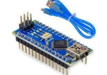
The Arduino Nano V3.0 is a compact, breadboard-friendly microcontroller board based on the ATmega328P. It is part of the Arduino platform and is designed for use in small projects and prototyping. The board includes a USB cable for easy connection to a computer for programming and power.
Key Features:
- ATmega328P microcontroller
- Compact size with 30mm x 18mm dimensions
- 22 digital I/O pins, of which 6 can be used as PWM outputs
- 8 analog input pins
- 32 KB Flash memory for program storage
- 2 KB SRAM for data storage
- 1 KB EEPROM for non-volatile data storage
- Built-in USB interface for easy programming
- Compatible with Arduino IDE for development
Technical Specifications:
- Microcontroller: ATmega328P
- Operating Voltage: 5V
- Input Voltage: 7-12V (through the power jack or USB)
- Digital I/O Pins: 22
- PWM Output Pins: 6
- Analog Input Pins: 8
- Flash Memory: 32 KB
- SRAM: 2 KB
- EEPROM: 1 KB
- Clock Speed: 16 MHz
- USB Interface: Mini-USB
- Dimensions: 30mm x 18mm
Applications:
- Prototyping and development for electronics projects
- Embedded systems and automation
- Robotics
- Sensor interfacing and data acquisition
- Educational projects and learning
Usage:
- Connection: Connect the Arduino Nano V3.0 to your computer using the included USB cable. The USB cable is used for both power and programming.
- Programming: Use the Arduino IDE to write and upload code to the board via the USB connection.
- Connection to Peripherals: Utilize the digital and analog I/O pins to connect sensors, actuators, and other peripherals.
- Power Supply: The board can be powered through the USB connection or via an external power source connected to the VIN pin.
Caution:
- Ensure correct voltage levels are used to avoid damaging the board. The recommended input voltage is 7-12V.
- Avoid short-circuiting the pins and connections.
- Handle the board and USB cable with care to prevent physical damage.
Datasheet:
For detailed technical specifications and pin configuration, refer to the Arduino Nano V3.0 Datasheet.
|
Description:
The Mega 2560 PRO with CH340 is a compact and powerful development board based on the ATmega2560 microcontroller. Designed for advanced applications, it offers extensive I/O capabilities, high processing power, and reliable USB communication via the CH340 chip. This board is ideal for projects requiring multiple interfaces, large memory, and robust performance.
Key Features:
- Microcontroller: ATmega2560 with 54 digital I/O pins, 16 analog inputs, and 4 UARTs.
- USB to Serial Communication: CH340 chip for reliable USB communication.
- Compact Design: Smaller form factor compared to standard Mega 2560 boards.
- High Memory Capacity: 256 KB Flash memory, 8 KB SRAM, and 4 KB EEPROM.
- Multiple Interfaces: I2C, SPI, and serial interfaces for versatile connectivity.
- Wide Operating Voltage Range: Supports 7-12V DC input voltage.
Technical Specifications:
- Microcontroller: ATmega2560
- Operating Voltage: 5V
- Input Voltage (recommended): 7-12V
- Digital I/O Pins: 54 (of which 15 provide PWM output)
- Analog Input Pins: 16
- DC Current per I/O Pin: 20 mA
- Flash Memory: 256 KB (8 KB used by bootloader)
- SRAM: 8 KB
- EEPROM: 4 KB
- Clock Speed: 16 MHz
- USB Controller: CH340
- Dimensions: Compact size for integration into various projects
Applications:
- Robotics: Ideal for controlling multiple motors, sensors, and other peripherals.
- Embedded Systems: Suitable for complex embedded system designs.
- IoT Projects: Can be used in Internet of Things (IoT) applications requiring extensive I/O and memory.
- Automation: Perfect for automation projects needing high processing power and multiple interfaces.
- Prototyping: Great for prototyping advanced electronics and software applications.
Datasheet:
For detailed technical information and specifications, please refer to the Mega 2560 PRO with CH340 Datasheet.
|
The USBASP 10PIN to 6PIN Adapter is a convenient tool designed to convert the 10-pin ISP (In-System Programming) interface to the 6-pin interface commonly used in various AVR microcontroller programming setups. This adapter allows for seamless integration of the USBASP programmer with devices that require a 6-pin connection, simplifying the process of programming and debugging AVR microcontrollers.
Key Features:
- 10-Pin to 6-Pin Conversion: Converts the standard 10-pin ISP interface to a 6-pin interface
- Compact Design: Small and lightweight, easy to use and carry
- High Compatibility: Compatible with a wide range of AVR microcontrollers and USBASP programmers
- Durable Construction: Made with quality materials for reliable and long-lasting use
- Ease of Use: Simplifies the connection process for programming and debugging
Technical Specifications:
- Connector Type: 10-pin IDC (In-circuit Debugging Connector) to 6-pin IDC
- Pin Configuration: Standard AVR ISP pinout
- Dimensions: Compact and easy to handle
- Material: Durable plastic and metal connectors
- Weight: Lightweight for portability
Applications:
- AVR microcontroller programming
- In-system programming (ISP) for development and prototyping
- Debugging and firmware updates
- Compatible with USBASP programmers
Usage:
- Connect the 10-pin side of the adapter to the USBASP programmer.
- Connect the 6-pin side of the adapter to the target AVR microcontroller or programming header.
- Ensure correct orientation and secure connections.
- Proceed with programming or debugging the AVR microcontroller using the USBASP programmer.
Caution:
- Ensure correct orientation of the connectors to avoid damage.
- Verify the pinout compatibility with your target microcontroller before use.
- Handle with care to prevent damage to the pins and connectors.
Datasheet:
For detailed technical specifications, refer to the USBASP 10PIN to 6PIN Adapter Datasheet.
|
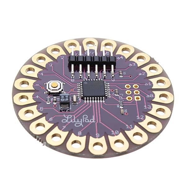
The Arduino LilyPad is a flexible and washable microcontroller board designed for e-textiles and wearable electronics. It is part of the Arduino platform and features a unique design that allows it to be integrated into fabric and clothing. The LilyPad is ideal for projects that require electronic components to be embedded in textiles, enabling creative and interactive wearable technology.
Key Features:
- Microcontroller: ATmega328P, similar to Arduino Uno
- Flexible Design: Can be sewn into fabric or clothing
- Washable: Water-resistant design for washable applications (note: always check the specific model’s washing instructions)
- Connectivity: Includes a range of I/O pins for connecting sensors, actuators, and other components
- Power Supply: Can be powered via USB or external battery pack
- Programming: Compatible with the Arduino IDE for easy programming
Technical Specifications:
- Dimensions:
- Weight: Approximately 10 g
- Operating Voltage: 2.7V to 5.5V DC
- Digital I/O Pins: 14 (of which 6 provide PWM output)
- Analog Input Pins: 6
- Flash Memory: 32 KB (ATmega328P) of which 0.5 KB used by bootloader
- SRAM: 2 KB (ATmega328P)
- EEPROM: 1 KB (ATmega328P)
- Clock Speed: 16 MHz
- Communication: UART, SPI, I2C
- Power Supply: Can be powered via USB or battery (battery not included)
- Connector Types: Sewable conductive thread or wire for connections
Applications:
- Wearable Technology: Ideal for creating interactive clothing and accessories.
- E-Textiles: Used in smart fabrics and textiles for embedded electronics.
- Education: Useful for teaching electronics and programming in a hands-on manner.
- DIY Projects: Perfect for hobbyists creating custom wearable gadgets.
- Interactive Art: Enables the creation of art installations that involve electronics and textiles.
Datasheet:
For detailed technical information, refer to the Arduino LilyPad Datasheet.
|
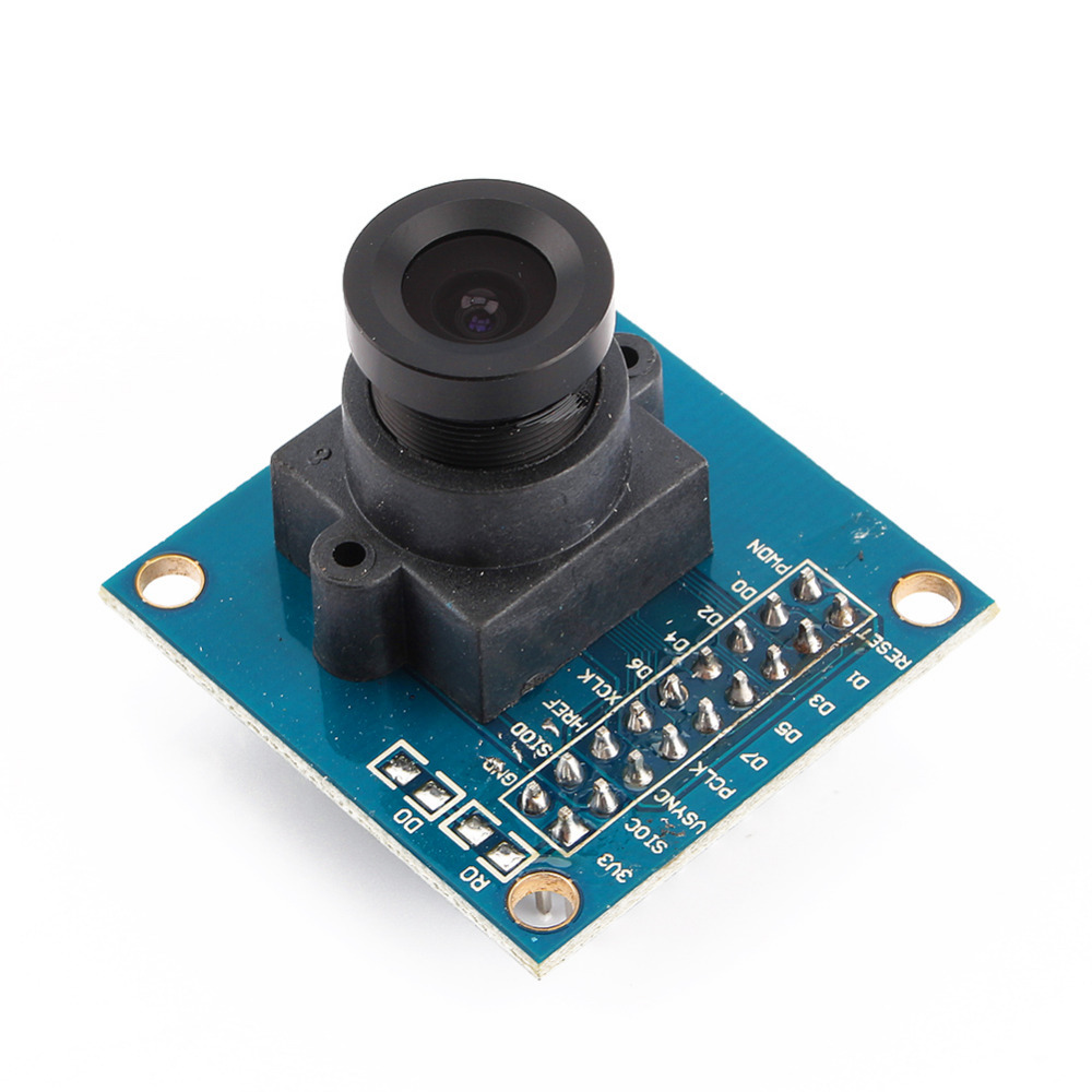
The OV7670 Camera Module is a low-cost camera module designed for use with Arduino and other microcontroller platforms. It features the OV7670 image sensor, which provides basic image capture capabilities suitable for low-resolution and hobbyist applications. This module is ideal for educational projects, DIY electronics, and simple image processing tasks.
Key Features:
- VGA (640×480) resolution capability
- Low power consumption
- Small form factor, easy to integrate with Arduino
- Includes an integrated image sensor (OV7670)
- Supports various output formats, including RGB565 and YUV422
- Built-in FIFO buffer to store image data temporarily
Technical Specifications:
- Image Sensor: OV7670 CMOS
- Resolution: VGA (640×480 pixels)
- Output Formats: RGB565, YUV422
- Power Supply: 3.3V DC (requires voltage regulator for Arduino 5V supply)
- Interface: 8-bit parallel data bus
- Operating Temperature Range: -20°C to +70°C
- Frame Rate: Up to 30 frames per second (fps) at VGA resolution
- Lens Type: Fixed-focus lens
Applications:
- Basic image capture and processing
- Educational and experimental projects involving image processing
- Low-resolution video streaming
- Simple security or surveillance systems
- Integration with Arduino for image-related applications
Usage:
- Connection: Connect the OV7670 module to the Arduino using the provided pin headers. Typically, connections include power (3.3V), ground, and data lines.
- Configuration: Use Arduino libraries and example code to configure the camera module and capture images. The module usually requires initialization and setup via I2C or SPI.
- Processing: Retrieve image data from the module and process it using Arduino or other compatible microcontrollers.
- Integration: Integrate the camera module into your project to enable image capturing or video streaming functionality.
Caution:
- The OV7670 operates at 3.3V, so be careful not to apply 5V directly to the module to avoid damage.
- Properly handle and secure the module to avoid damage to the delicate components.
- Ensure correct wiring and connections according to the module’s datasheet to avoid communication issues.
Datasheet:
For detailed technical specifications, refer to the OV7670 Camera Module Datasheet.
|
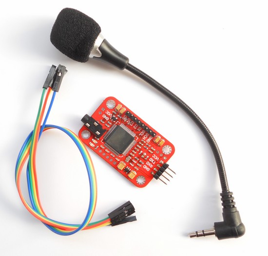
The Voice Recognition Module V3 is a compact and easy-to-use voice recognition module designed for embedded systems. It can be trained to recognize voice commands and respond accordingly, making it ideal for applications in home automation, robotics, and interactive projects. The module supports up to 80 voice commands, with 7 commands being recognized at any given time.
Key Features:
- Supports up to 80 voice commands
- Recognizes 7 voice commands simultaneously
- Speaker-independent and speaker-dependent modes
- Easy UART interface for communication with microcontrollers
- Onboard microphone for voice input
- Low power consumption
- Supports multiple languages
- High accuracy and fast response time
Technical Specifications:
- Supply Voltage: 4.5V to 5.5V
- Current Consumption: 50 mA (max)
- Interface: UART (9600 bps default)
- Recognition Accuracy: 99%
- Recognition Time: < 1 second
- Number of Commands: 80 (in groups of 7)
- Operating Temperature Range: -40°C to +85°C
- Dimensions: 30mm x 20mm x 5mm
Applications:
- Home automation systems
- Voice-controlled robots
- Interactive toys and games
- Voice-activated devices
- Security systems
- Assistive technologies for the disabled
Usage:
- Connection:
- Connect the VCC pin to a 5V power supply.
- Connect the GND pin to ground.
- Connect the RX pin to the TX pin of the microcontroller.
- Connect the TX pin to the RX pin of the microcontroller.
- Training:
- Use the provided software or serial commands to train the module with voice commands.
- Train the module in a quiet environment for best results.
- Store the voice commands in one of the available groups.
- Operation:
- After training, the module can recognize voice commands and send corresponding signals to the microcontroller.
- Use the recognized commands to control devices, trigger actions, or execute programs.
- Programming:
- Write a program on the microcontroller to interface with the module and handle recognized commands.
- Use the UART interface to send and receive data from the module.
Caution:
- Avoid exposing the module to high levels of noise during operation.
- Handle the module carefully to avoid damage from electrostatic discharge (ESD).
- Ensure proper power supply and connections to prevent malfunction.
Datasheet:
For detailed technical specifications, refer to the Voice Recognition Module V3 Datasheet.
|
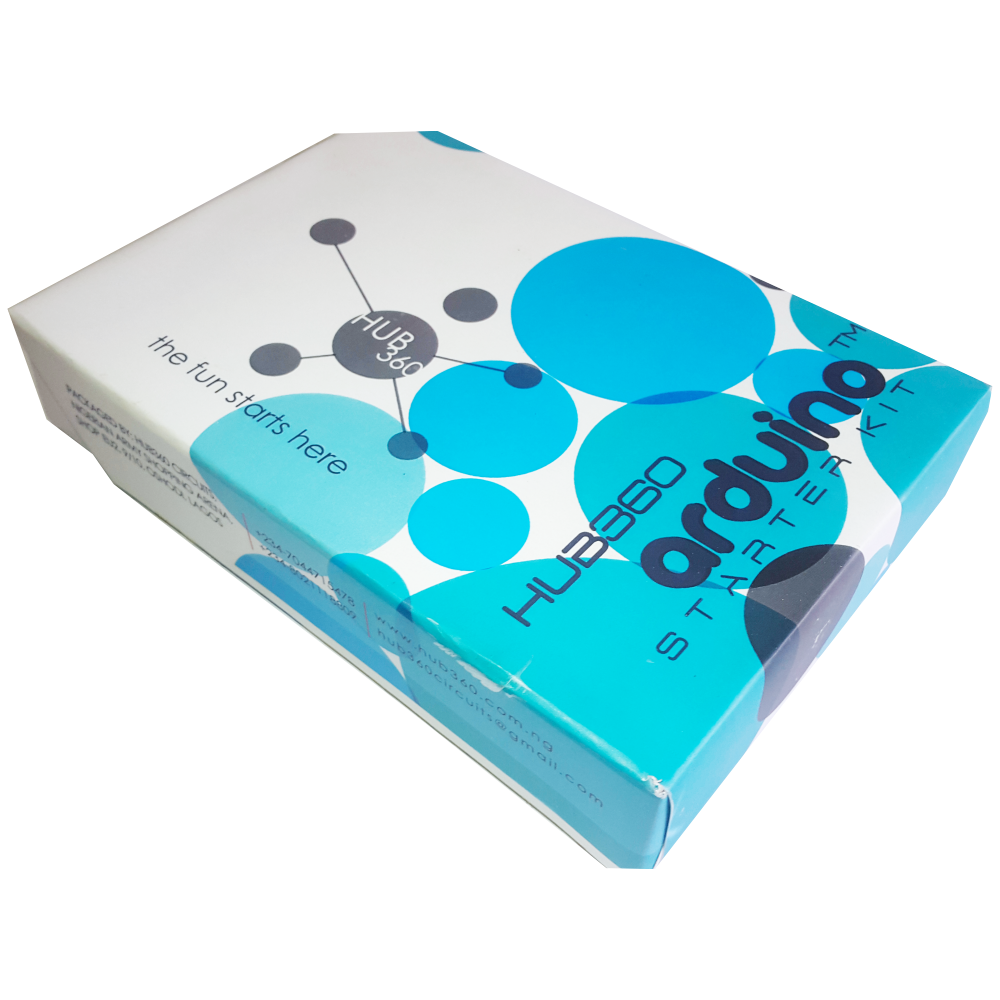
The Hub360 Arduino Starter Kit is a comprehensive package designed for beginners and enthusiasts looking to dive into the world of electronics and programming. This kit includes Arduino Uno, which is a microcontroller board based on the ATmega328P. The kit provides a variety of components and modules to help users learn and experiment with different electronic projects and concepts.
Key Features:
- Includes Arduino Uno board
- Comprehensive set of components and modules for various projects
- Ideal for beginners and hobbyists
- Detailed tutorial and project guide included
- USB interface for easy programming and power
- Compatible with Arduino IDE and various libraries
Technical Specifications:
- Microcontroller: ATmega328P
- Operating Voltage: 5V
- Input Voltage (recommended): 7-12V
- Digital I/O Pins: 14 (6 PWM outputs)
- Analog Input Pins: 6
- DC Current per I/O Pin: 20mA
- Flash Memory: 32KB (ATmega328P) of which 0.5KB used by bootloader
- SRAM: 2KB (ATmega328P)
- EEPROM: 1KB (ATmega328P)
- Clock Speed: 16 MHz
Kit Contents:
- ARDUINO BOARD 1
- ARDUINO USB CABLE 1
- ARDUINO BATTERY CONNECTOR 1
- 400 HOLE BREADBOARD 1
- LED (RED, YELLOW , GREEN, WHITE) 20
- RGB LED 1
- JUMPER WIRE(M-M, M-F, F-F) 120
- PHOTORESISTOR (LDR) 3
- MALE HEADERS 40
- ULTRASONIC SENSOR 1
- FLAME SENSOR 1
- TEMP./HUMIDITY SENSOR 1
- TILT SENSOR 1
- LASER SENSOR 1
- PIR MOTION SENSOR 1
- RESISTORS(220K, 1K, 10K,100K) 40
- 7 SEGMENT DISPLAY 1
- SG90 SERVO 1
- REMOTE CONTROL 1
- BUZZER 1
- 2N2222 2
- TSOP 1838 1
- RF TRANSMITTER 1
- RF RECEIVER 1
- TACT SWITCH 5
- 16*2 LCD DISPLAY
Applications:
- Learning basic electronics and programming
- Building interactive projects and prototypes
- Developing skills in microcontroller-based design
- Experimenting with sensors and actuators
- Creating DIY electronic devices
Usage:
- Setup:
- Connect the Arduino Uno board to your computer using the USB cable.
- Install the Arduino IDE and configure it to recognize the board.
- Programming:
- Write or upload sample code (sketches) to the Arduino board using the Arduino IDE.
- Utilize the provided components and modules to build and test different circuits.
- Experimentation:
- Follow the detailed tutorials and project guide to create various projects.
- Modify and expand on the sample projects to enhance learning and creativity.
Caution:
- Handle the components carefully to avoid damage.
- Ensure proper connections and polarity to prevent short circuits or component failure.
- Verify the code and circuit connections before powering the board.
Datasheet:
For detailed technical specifications of the Arduino Uno, refer to the Arduino Uno Datasheet.
|
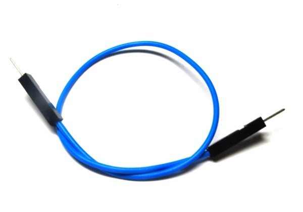
A single male-male jumper wire features male connectors on both ends and is used for making connections between components, breadboards, and other circuit boards. These wires are essential in prototyping and development for creating temporary circuits or testing designs. They allow for easy and flexible connections without the need for soldering.
Key Features:
- Connectors: Male connectors on both ends
- Wire Type: Flexible, insulated wire for easy handling and routing
- Length: Available in various lengths to suit different project needs
- Color-Coded: Available in multiple colors for easy identification and organization
- Durability: Made from high-quality materials for reliable and repeated use
- Compatibility: Suitable for standard 2.54mm (0.1 inch) pitch headers and connectors
Technical Specifications:
- Connector Type: Male-to-male
- Wire Gauge: Typically 28 AWG
- Insulation Material: PVC or similar flexible plastic
- Pitch: 2.54mm (0.1 inch)
- Length Options: Common lengths include 10cm, 20cm, 30cm, and others
- Operating Temperature: Typically -40°C to +80°C
- Current Rating: Usually up to 1A
Applications:
- Prototyping: Ideal for making connections on breadboards and development boards.
- Educational Projects: Used in educational settings to teach electronics and programming concepts.
- DIY Electronics: Suitable for hobbyists and makers working on various electronics projects and experiments.
- Temporary Connections: Useful for creating temporary connections during development and testing.
- Interfacing Components: Facilitates connections between components and modules with male pin headers.
|
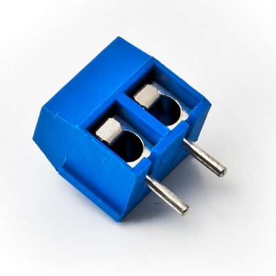
The 2-Way PCB Screw Terminal is a compact and reliable connector used to securely attach and disconnect wires on a printed circuit board (PCB). It features two screw terminals for connecting two wires, providing a stable and durable connection for various electronic and electrical applications. This type of terminal is commonly used in power distribution, signal connections, and modular systems.
Key Features:
- Two screw terminals for easy wire connection
- Suitable for use with PCB for secure mounting
- Provides a reliable and durable electrical connection
- Simple and convenient for quick wire insertion and removal
- Supports various wire gauges and types
- Compact design for space-saving on PCB
Technical Specifications:
- Number of Positions: 2
- Terminal Type: Screw
- Mounting Type: PCB (Printed Circuit Board)
- Wire Gauge Range: Typically 22-12 AWG (varies by manufacturer)
- Insulation Material: Polyamide (PA) or other suitable insulating materials
- Terminal Material: Brass or copper with tin plating
- Operating Voltage: Typically up to 300V (depends on the specific terminal rating)
- Operating Temperature Range: -40°C to +105°C
- Package Type: Typically available in strips or individual connectors
Applications:
- Power supply connections
- Signal wiring and distribution
- Modular and expandable systems
- Industrial equipment
- Consumer electronics
Usage:
- Mount the 2-Way PCB Screw Terminal onto the PCB by inserting it into the designated holes.
- Secure the terminal to the PCB by soldering the pins or using mechanical locking methods (if applicable).
- Strip the insulation from the wires to the appropriate length.
- Insert the stripped wires into the terminal and tighten the screws to secure the wires in place.
Caution:
- Ensure the terminal is rated for the voltage and current levels used in your application.
- Avoid over-tightening the screws to prevent damage to the terminal or wires.
- Verify proper wire insulation stripping to ensure reliable connections.
Datasheet:
For detailed technical specifications, refer to the 2-Way PCB Screw Terminal Datasheet.
|
