|
Description |
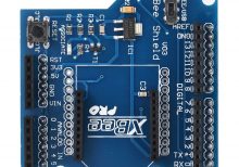
The Arduino XBee Expansion Board V3.0 is designed to facilitate easy integration of XBee modules with Arduino boards, providing a convenient platform for wireless communication projects. It allows XBee modules (such as XBee 802.15.4, Zigbee, or others) to be easily plugged into Arduino boards, enabling wireless communication capabilities without the need for extensive wiring.
Key Features:
- Compatibility: Compatible with Arduino Uno, Mega, and other compatible boards.
- XBee Socket: Provides a socket for XBee modules, supporting various XBee module types.
- Onboard Components: Includes necessary components for XBee module operation.
- Power Options: Supports both 3.3V and 5V operation, selectable via jumpers.
- Reset Button: Onboard reset button for resetting connected Arduino and XBee modules.
- Interface: Provides UART interface for communication between Arduino and XBee modules.
- Indicator LEDs: LEDs for power and status indication.
- Expansion Headers: Additional headers for connecting to Arduino I/O pins.
Applications:
- Wireless sensor networks
- Remote monitoring and control systems
- IoT (Internet of Things) projects
- Home automation systems
- Robotics and automation projects
Technical Specifications:
- Dimensions: Standard Arduino shield dimensions
- Power Supply: 5V DC input via Arduino board or external power source
- Communication: UART interface between Arduino and XBee module
- Operating Temperature: Typically -40°C to +85°C
Datasheet: For detailed technical information, refer to the Arduino XBee Expansion Board V3.0 datasheet.
|
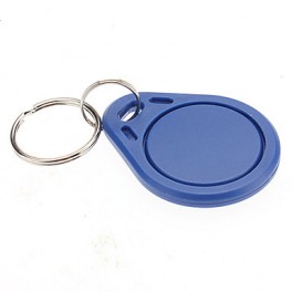
The 125KHZ RFID Key Chain is a compact and durable radio-frequency identification (RFID) device used for access control and identification applications. It operates at a frequency of 125kHz and is compatible with standard RFID readers. The key chain format makes it convenient to carry and use for various applications such as security systems, attendance tracking, and asset management.
Key Features:
- Operates at 125kHz frequency
- Durable and compact key chain design
- Compatible with standard RFID readers
- Unique identification number (UID) for each key chain
- Waterproof and shock-resistant
- Long read range (up to 10 cm depending on the reader)
- No battery required (passive RFID technology)
Technical Specifications:
- Operating Frequency: 125kHz
- Material: ABS plastic
- Dimensions: Approximately 40mm x 32mm x 4mm
- Weight: Approximately 6g
- Read Range: Up to 10 cm (depending on the reader and environment)
- Data Storage: 64-bit read-only unique identifier (UID)
- Operating Temperature Range: -25°C to +85°C
- Color: Typically blue, but may vary by manufacturer
- Waterproof: Yes
Applications:
- Access control systems
- Time and attendance tracking
- Membership management
- Asset tracking
- Secure entry systems
- Contactless payment systems
Usage:
- Integration:
- Enroll the RFID key chain in the desired RFID system by registering its unique identifier (UID) with the system’s database.
- Operation:
- Present the key chain to an RFID reader within the read range (up to 10 cm).
- The reader will capture the UID and communicate it to the control system for processing.
- Security:
- Use the key chain for secure access to restricted areas or for tracking attendance.
- Pair the key chain with a compatible RFID reader and control system for seamless operation.
Caution:
- Avoid exposing the key chain to extreme temperatures or harsh chemicals.
- Do not bend or apply excessive force to the key chain to prevent damage.
- Keep the key chain away from strong magnetic fields to ensure proper operation.
Datasheet:
For detailed technical specifications, refer to the manufacturer’s datasheet for your specific 125kHz RFID key chain model.
|
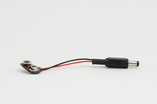
The Arduino 9V Battery Connector is a convenient accessory for powering Arduino boards and other compatible devices. It allows you to connect a standard 9V battery to the Arduino’s power jack, providing a portable power solution for your projects. This connector is essential for mobile and battery-operated applications, offering an easy and reliable way to supply power to your electronics.
Key Features:
- Compatible with standard 9V batteries
- Easy to connect and use
- Provides a secure and stable power connection
- Compact and portable design
- Durable construction for long-lasting use
- Standard DC barrel plug compatible with Arduino boards
Technical Specifications:
- Connector Type: DC barrel plug (center-positive)
- Barrel Plug Dimensions: Outer diameter 5.5mm, inner diameter 2.1mm
- Battery Connector Type: Snap-on connector for 9V battery
- Cable Length: Approximately 15 cm
- Material: Plastic and metal connectors with insulated wire
- Color: Typically black with red and black wires
Applications:
- Portable Arduino projects
- Battery-operated electronics
- Prototyping and testing
- Educational kits
- DIY electronics
Usage:
- Connection:
- Snap the 9V battery connector onto the terminals of a standard 9V battery.
- Insert the DC barrel plug into the power jack of your Arduino board or compatible device.
- Powering:
- Ensure the polarity of the connections is correct (center-positive) to avoid damage to the board.
- The Arduino will draw power from the 9V battery through the connector.
- Monitoring:
- Monitor the battery voltage periodically to ensure it remains within the acceptable range for your Arduino board (typically 7-12V).
Caution:
- Ensure the connector is securely attached to the battery terminals to prevent intermittent connections.
- Avoid short-circuiting the battery terminals.
- Do not expose the connector to moisture or extreme temperatures.
- Remove the battery from the connector when not in use to prevent battery drain.
Datasheet:
Refer to the manufacturer’s guidelines or specifications for further details.
|
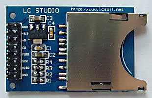
The SD Card Module is a compact and efficient solution for adding storage capabilities to your microcontroller or development board projects. It allows you to read from and write to SD cards, making it ideal for data logging, file storage, and other applications requiring large amounts of memory. The module supports various SD card formats and interfaces seamlessly with popular microcontrollers like Arduino, Raspberry Pi, and others.
Key Features:
- Storage: Supports SD, SDHC, and MicroSD (with adapter) cards
- Interface: SPI interface for easy integration
- Voltage Compatibility: Operates at 3.3V and 5V
- Onboard 3.3V Regulator: Ensures stable operation
- Card Detection: Built-in card detection switch
- Compact Design: Small footprint for easy incorporation into projects
- File System: Compatible with FAT16 and FAT32 file systems
Technical Specifications:
- Supported Cards: SD, SDHC, MicroSD (with adapter)
- Operating Voltage: 3.3V/5V
- Interface: SPI
- Current Consumption: < 100mA
- File System: FAT16, FAT32
- Dimensions: 42mm x 24mm x 12mm
Applications:
- Data Logging: Store sensor data and logs in embedded systems.
- File Storage: Save files for multimedia applications and projects.
- Firmware Updates: Load new firmware from the SD card for microcontrollers.
- DIY Projects: Perfect for hobbyists needing additional storage.
- Educational Projects: Commonly used in learning modules for data storage and retrieval.
Usage:
- Wiring: Connect the SD card module to your microcontroller using the SPI interface (CS, MOSI, MISO, SCK, VCC, GND).
- Power Supply: Ensure the module is powered with 3.3V or 5V, as required.
- Card Insertion: Insert a formatted SD card into the module.
- Programming: Use libraries (e.g., SD library for Arduino) to initialize the SD card and read/write data.
- Data Handling: Store or retrieve data files from the SD card as needed by your application.
Caution:
- Voltage Levels: Ensure proper voltage levels to avoid damaging the module.
- Handling SD Cards: Handle SD cards with care to prevent data loss or corruption.
Datasheet:
For detailed technical specifications, refer to the SD Card Module Datasheet.
|
The Arduino Mega Case is a protective enclosure designed to house and safeguard the Arduino Mega microcontroller board. This case is ideal for ensuring the board remains secure during use, while also providing easy access to its ports and connectors. It is typically made from durable materials such as plastic or acrylic, offering both protection and functionality for various projects and applications.
Key Features:
- Protective Enclosure: Shields the Arduino Mega board from physical damage, dust, and debris
- Material: Often made from sturdy plastic or acrylic for durability and lightweight protection
- Access Ports: Designed with cutouts or openings for easy access to connectors, buttons, and LEDs
- Ventilation: Includes ventilation holes or slots to prevent overheating
- Mounting Options: May include mounting holes or clips for secure attachment of the Arduino Mega board
Technical Specifications:
- Material: Plastic or acrylic
- Compatibility: Specifically designed for Arduino Mega 2560 or similar models
- Dimensions: Custom-fit for Arduino Mega board size, typically around 115mm x 65mm x 25mm
- Color: Available in various colors, including clear, black, or colored options
- Ventilation: Ventilation slots or holes for heat dissipation
Applications:
- Protection of Arduino Mega boards in various projects
- Use in educational settings and development environments
- Housing for DIY electronics and robotics projects
- Secure enclosure for Arduino-based prototypes and final products
Usage:
- Placement: Insert the Arduino Mega board into the case, aligning with mounting holes or clips.
- Securing: Fasten the board within the case using screws or clips as provided.
- Access: Use the case’s cutouts to connect cables and peripherals to the Arduino Mega board.
- Ventilation: Ensure that ventilation openings are unobstructed for proper cooling.
Caution:
- Fit: Verify that the case is compatible with your specific Arduino Mega model.
- Ventilation: Ensure that ventilation slots are not blocked to prevent overheating.
- Handling: Handle with care to avoid cracking or damaging the case.
Datasheet:
For detailed technical specifications, refer to the Arduino Mega Case Datasheet.
|
The Push and Hold Switch is a type of momentary switch designed to activate a circuit only while it is being pressed. This switch maintains its contact state as long as the user continues to hold it down, and returns to its default position once released. It is commonly used in applications where continuous activation is needed for a function, such as in temporary control circuits, safety devices, and interactive electronics.
Key Features:
- Momentary action: activates only while held down
- Provides tactile feedback for user confirmation
- Available in various sizes and mounting styles
- Reliable and durable for repeated use
- Can be used for both AC and DC applications
- Simple installation with clear actuation feedback
Technical Specifications:
- Type: Momentary (normally open)
- Actuation Force: Varies by model (typically between 100g and 300g)
- Contact Rating: Typically 1A at 12V DC or 0.5A at 250V AC (check specific model)
- Contact Resistance: <50Ω
- Insulation Resistance: >100MΩ at 250V DC
- Dielectric Strength: 500V AC for 1 minute
- Operating Temperature Range: -20°C to +70°C
- Mounting Style: Panel mount, surface mount, or through-hole (varies by model)
Applications:
- Temporary control functions in electronic devices
- Safety switches in machinery
- Interactive user interfaces
- Alarm systems and emergency controls
- Testing and calibration equipment
Usage:
- Mount the Push and Hold Switch on the desired panel or enclosure using the appropriate mounting method.
- Connect the switch terminals to the control circuit, ensuring proper alignment and connection.
- Test the switch to verify that it activates the circuit only while held down and returns to its default state when released.
- Ensure the switch is securely mounted and properly insulated to avoid accidental activation or short circuits.
Caution:
- Avoid applying excessive force that might damage the switch or its mounting.
- Ensure correct voltage and current ratings for the specific application to prevent overheating or damage.
- Handle the switch carefully to avoid physical damage or degradation of the internal components.
Datasheet:
For detailed technical specifications, refer to the Push and Hold Switch Datasheet.
|


