|
Description |
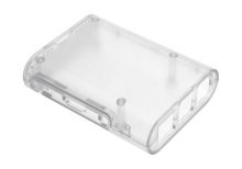
The Raspberry Pi 3 Transparent Injection Case is a protective enclosure designed for the Raspberry Pi 3 Model B and Model B+. It provides a clear, durable case that allows easy viewing of the Raspberry Pi while protecting it from dust, damage, and physical impact. The case is made from high-quality injection-molded plastic, ensuring a precise fit and a sleek, modern look.
Key Features:
- Transparent design for visibility of the Raspberry Pi board
- Injection-molded plastic construction for durability
- Precise cutouts for all ports, connectors, and GPIO pins
- Easy access to SD card slot and USB ports
- Ventilation slots for effective heat dissipation
- Simple snap-together assembly; no tools required
- Includes mounting hardware and rubber feet for stability
Technical Specifications:
- Material: Transparent injection-molded plastic
- Compatibility: Raspberry Pi 3 Model B and Model B+
- Color: Clear/Transparent
- Dimensions: Varies slightly by manufacturer (typically around 90mm x 60mm x 30mm)
- Weight: Varies slightly by manufacturer (typically around 50g)
Applications:
- Protecting Raspberry Pi 3 during use and handling
- Displaying the Raspberry Pi while maintaining access to ports
- Enclosing Raspberry Pi in a professional or educational setting
- Enhancing the aesthetics of Raspberry Pi-based projects
Usage:
- Place the Raspberry Pi 3 into the case, aligning it with the cutouts and mounting points.
- Snap the case parts together to secure the Raspberry Pi in place.
- Ensure all ports and connectors are accessible through the case openings.
- Mount the case using the included rubber feet or screws if required.
Caution:
- Handle the case carefully to avoid scratches or cracks.
- Ensure proper ventilation to prevent overheating of the Raspberry Pi.
- Verify that all connectors and ports are aligned and accessible before use.
Datasheet:
For detailed technical specifications, refer to the Raspberry Pi 3 Transparent Injection Case database.
|
The LiPo Battery 7.4V 2400mAh is a rechargeable lithium polymer battery commonly used in high-performance applications such as drones, RC vehicles, and other electronics. Its high capacity and stable voltage make it suitable for applications requiring reliable and extended power supply. This battery offers a balance between size, weight, and power output.
Key Features:
- Voltage: 7.4V (nominal)
- Capacity: 2400mAh
- Chemistry: Lithium Polymer (LiPo)
- Discharge Rate: Typically high discharge rates available (e.g., 20C to 30C)
- Charge Rate: Safe charging rate, typically 1C (2400mA)
- Compact Design: Lightweight and compact for easy integration
- Protection Circuit: Often includes built-in protection to prevent overcharging and over-discharging (varies by manufacturer)
Technical Specifications:
- Dimensions:
- Length: 100 mm (typical)
- Width: 35 mm (typical)
- Height: 15 mm (typical)
- Weight: Approximately 150 g
- Nominal Voltage: 7.4V
- Capacity: 2400mAh
- Discharge Rate:
- Continuous: Typically 20C to 30C (e.g., 48A to 72A)
- Peak: Higher rates available depending on model
- Charge Rate: 1C (2400mA) or as specified by manufacturer
- Connector Type: JST or XT60 (varies by model)
- Battery Type: Lithium Polymer (LiPo)
- Protection Circuit: Built-in protection (varies by model)
Applications:
- Drones: Provides power for multirotor drones and other UAVs.
- RC Vehicles: Suitable for remote-controlled cars, boats, and planes.
- Electronics Projects: Ideal for DIY electronics and prototyping projects requiring reliable power.
- High-Power Devices: Used in devices requiring high discharge rates and extended battery life.
Datasheet:
For detailed technical information, refer to the LiPo Battery 7.4V 2400mAh Datasheet.
|
The Raspberry Pi 3.5 Inches Resistive Touch Screen is a compact display module designed specifically for use with Raspberry Pi boards. This touch screen offers a user-friendly interface for various applications, allowing you to interact directly with your Raspberry Pi projects. It features a resistive touch panel, making it suitable for applications that require precise touch input.
Key Features:
- Screen Size: 3.5 inches
- Display Type: TFT LCD
- Resolution: 320 x 480 pixels
- Touch Type: Resistive touch panel
- Interface: SPI (Serial Peripheral Interface)
- Compatibility: Compatible with Raspberry Pi models such as Raspberry Pi 4, 3, 2, and Zero
Technical Specifications:
- Screen Size: 3.5 inches
- Display Resolution: 320 x 480 pixels
- Touch Panel: Resistive
- Interface: SPI
- Operating Voltage: 3.3V/5V (powered through Raspberry Pi GPIO)
- Dimensions: Approximately 85mm x 55mm x 30mm
- Viewing Angle: Wide viewing angle
- Backlight: LED backlight for enhanced visibility
Applications:
- Portable Raspberry Pi projects
- DIY handheld devices
- Control interfaces for home automation
- Interactive displays for education and prototyping
- Gaming consoles and entertainment systems
Usage:
- Connect the 3.5-inch touch screen to the GPIO pins of your Raspberry Pi board.
- Install the necessary drivers and configure the Raspberry Pi for the touch screen.
- Calibrate the touch panel if required to ensure accurate touch input.
- Use the touch screen to interact with your Raspberry Pi applications, projects, or operating system.
Caution:
- Handle the touch screen carefully to avoid damaging the display or touch panel.
- Ensure the GPIO pins are correctly connected to avoid short circuits or incorrect operation.
- Follow the manufacturer’s guidelines for driver installation and configuration.
Datasheet:
For detailed technical specifications, refer to the Raspberry Pi 3.5 Inches Resistive Touch Screen Datasheet.
|
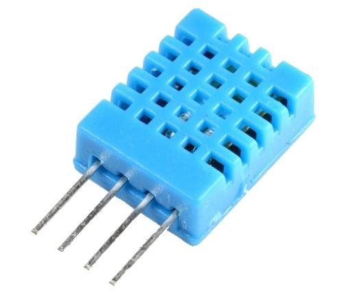
The DHT11 is a basic, ultra-low-cost digital temperature and humidity sensor. It uses a capacitive humidity sensor and a thermistor to measure the surrounding air and outputs a digital signal on the data pin. It’s simple to use but requires careful timing to grab data. It’s perfect for DIY projects, weather stations, and other applications where accurate and reliable temperature and humidity readings are needed.
Key Features:
- Temperature Range: 0-50°C with ±2°C accuracy
- Humidity Range: 20-80% RH with ±5% RH accuracy
- Low Power Consumption: Efficient for battery-operated applications
- Single Wire Digital Interface: Easy to interface with microcontrollers
- Pre-calibrated: No need for additional calibration
- Compact Size: Suitable for compact projects and devices
Technical Specifications:
- Temperature Range: 0-50°C (32-122°F)
- Humidity Range: 20-80% RH
- Temperature Accuracy: ±2°C
- Humidity Accuracy: ±5% RH
- Operating Voltage: 3.3V to 5.5V
- Max Current: 2.5mA
- Output: Digital signal via 1-wire protocol
- Dimensions: 15.5mm x 12mm x 5.5mm
Applications:
- Weather Stations: Monitor and log temperature and humidity levels.
- Home Automation: Control HVAC systems based on environmental conditions.
- Greenhouses: Maintain optimal growing conditions for plants.
- DIY Projects: Perfect for hobbyists building custom sensors and gadgets.
- Data Loggers: Record environmental data over time for analysis.
- Educational Projects: Teach students about sensors and data acquisition.
Usage:
- Wiring: Connect the VCC pin to 3.3V or 5V, GND to ground, and the DATA pin to a digital input on your microcontroller.
- Library Integration: Use libraries available for platforms like Arduino or Raspberry Pi to simplify reading data from the sensor.
- Coding: Write code to initialize the sensor and read temperature and humidity data.
- Data Processing: Process and use the sensor data in your application as needed, such as displaying it on an LCD or sending it to a web server.
Caution:
- Power Supply: Ensure the sensor is supplied with the correct voltage to avoid damage.
- Environmental Conditions: Keep the sensor in a dust-free, non-condensing environment for accurate readings.
- Wiring Length: Minimize the length of wiring between the sensor and the microcontroller to maintain signal integrity.
Datasheet:
For detailed technical specifications, refer to the DHT11 Datasheet.
|
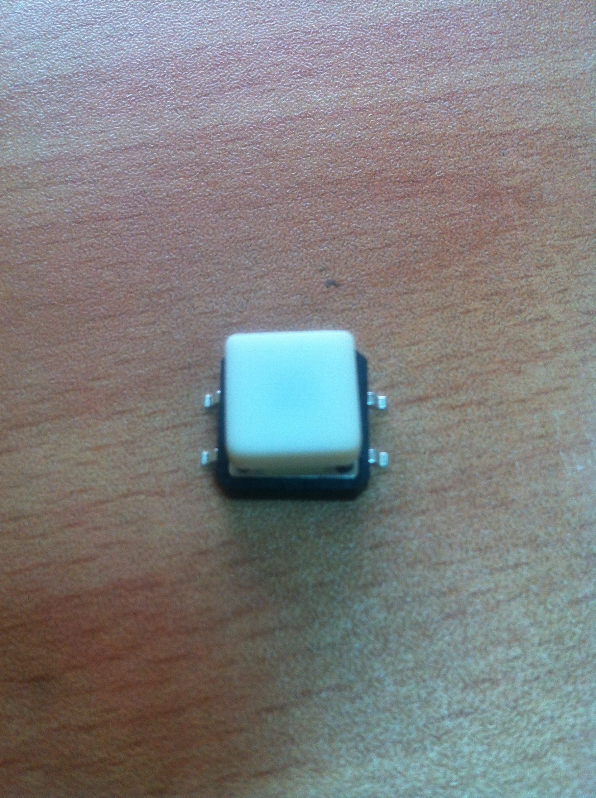
The SMD (Surface-Mount Device) tact switch with cap is a compact, reliable switch used in various electronic devices and applications. The switch is mounted directly onto a printed circuit board (PCB) and is designed to be activated by pressing the cap. The cap provides a user-friendly interface and helps in guiding the pressing action.
Key Features:
- Type: SMD Tactile Switch
- With Cap: Includes a cap for easy pressing and improved tactile feedback
- Mounting Type: Surface-mount for easy PCB integration
- Actuation Force: Typically designed for low actuation force
- Switch Function: Momentary contact (normally open; closes when pressed)
- Durability: Designed for many cycles of operation
Technical Specifications:
- Package Type: SMD (Surface-Mount Device)
- Cap Type: Plastic or rubber cap for tactile feedback
- Actuation Force: Typically ranges from 100g to 500g (varies by model)
- Contact Rating: Generally rated for 50mA to 100mA at 12V (varies by model)
- Contact Resistance: Typically 100Ω or less
- Insulation Resistance: Typically 100MΩ or more
- Life Cycle: Rated for up to 1,000,000 cycles
- Operating Temperature Range: -20°C to +85°C
Applications:
- Consumer Electronics: Used in devices like remote controls, calculators, and handheld devices
- Industrial Equipment: Integrated into control panels and user interfaces
- Automotive: Utilized in dashboards and control systems
- Medical Devices: Employed in compact medical equipment and interfaces
Usage:
- PCB Mounting: Solder the SMD tact switch to the designated pads on the PCB.
- Cap Placement: Ensure the cap is securely placed on the switch for proper operation and tactile feedback.
- Testing: Test the switch to ensure it functions correctly and provides the desired tactile response.
- Integration: Integrate the switch into the final assembly and connect it to the necessary circuits or components.
Caution:
- Handling: Handle with care to avoid damaging the switch or cap.
- Soldering: Follow proper soldering techniques to avoid overheating or damaging the switch.
- Compatibility: Ensure the switch is compatible with the design requirements and PCB layout.
Datasheet:
For detailed technical specifications and mounting guidelines, refer to the manufacturer’s datasheet for the specific SMD tact switch model.
|
The Raspberry Pi GPIO Expansion Board is designed to extend the General Purpose Input/Output (GPIO) capabilities of the Raspberry Pi. This board provides additional headers for easy connection of various sensors, modules, and devices. It is an essential accessory for prototyping and experimenting with the Raspberry Pi, allowing users to access more GPIO pins and make connections more manageable.
Key Features:
- Expands the GPIO pins of the Raspberry Pi
- Easy-to-use design with labeled pins
- Provides additional headers for quick connections
- Compatible with Raspberry Pi models
- Supports various add-ons and modules
- Durable construction for reliable performance
Technical Specifications:
- Compatibility: Raspberry Pi models (e.g., Raspberry Pi 3, 4, Zero)
- Number of GPIO Pins: 40-pin expansion
- Headers: Male and female headers for easy connections
- Dimensions: Standard size to fit Raspberry Pi form factor
- Material: High-quality PCB with gold-plated connectors
Applications:
- Prototyping and experimentation with Raspberry Pi
- Connecting multiple sensors and modules
- Educational projects and learning electronics
- Home automation and IoT projects
- Robotics and embedded systems development
Usage:
- Connect the expansion board to the GPIO header of the Raspberry Pi.
- Secure the board in place to ensure a stable connection.
- Use the additional headers to connect various sensors, modules, and devices.
- Access the extended GPIO pins through the labeled headers for easy reference.
- Program the Raspberry Pi to interface with the connected components.
Caution:
- Ensure proper alignment of the expansion board with the Raspberry Pi GPIO header.
- Avoid connecting incompatible devices that may damage the GPIO pins.
- Handle the board with care to prevent static discharge and damage.
|
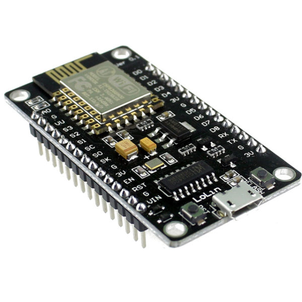
The ESP8266 NodeMcu LUA WiFi Development Board is an open-source IoT platform. It integrates the ESP8266 WiFi module, which allows for easy development of WiFi-based applications. The board includes the Lua scripting language for programming, enabling quick and efficient development. This development board is highly suitable for beginners and professionals looking to build IoT projects due to its simplicity, low cost, and robust capabilities.
Key Features:
- WiFi Module: Integrated ESP8266 with full TCP/IP stack and microcontroller capability
- Programming Language: Lua scripting language support
- GPIO: Multiple GPIO pins available for connecting sensors and actuators
- USB Interface: On-board USB to serial interface for easy programming
- Memory: 4MB Flash Memory
- Power Supply: Can be powered via micro USB or external power supply
- Built-in Antenna: On-board WiFi antenna for wireless connectivity
- Compact Size: Small form factor for easy integration into projects
Technical Specifications:
- Dimensions: 48 mm x 26 mm
- Weight: Approximately 10 g
- Operating Voltage: 3.3V
- Digital I/O Pins: 11
- Analog Input Pins: 1 (max input 3.2V)
- Clock Speed: 80 MHz
- Flash Memory: 4MB
- USB to UART: CP2102 or CH340G
- Power Consumption:
- Deep Sleep: <10 μA
- Light Sleep: <1 mA
- Modem Sleep: ~15 mA
- Active Mode: ~70 mA
- WiFi Standards: 802.11 b/g/n
- Connector Types: Micro USB, GPIO headers
Applications:
- IoT Projects: Ideal for developing Internet of Things applications with WiFi connectivity.
- Home Automation: Control and monitor home appliances and systems remotely.
- Prototyping: Rapid development and testing of WiFi-enabled prototypes.
- Wireless Sensor Networks: Creating networks of sensors with real-time data collection and communication.
- Smart Devices: Integrating WiFi capabilities into various smart devices and gadgets.
Datasheet:
For detailed technical information, refer to the ESP8266 NodeMcu LUA WiFi Development Board Datasheet.
|
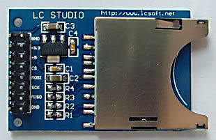
The SD Card Module is a compact and efficient solution for adding storage capabilities to your microcontroller or development board projects. It allows you to read from and write to SD cards, making it ideal for data logging, file storage, and other applications requiring large amounts of memory. The module supports various SD card formats and interfaces seamlessly with popular microcontrollers like Arduino, Raspberry Pi, and others.
Key Features:
- Storage: Supports SD, SDHC, and MicroSD (with adapter) cards
- Interface: SPI interface for easy integration
- Voltage Compatibility: Operates at 3.3V and 5V
- Onboard 3.3V Regulator: Ensures stable operation
- Card Detection: Built-in card detection switch
- Compact Design: Small footprint for easy incorporation into projects
- File System: Compatible with FAT16 and FAT32 file systems
Technical Specifications:
- Supported Cards: SD, SDHC, MicroSD (with adapter)
- Operating Voltage: 3.3V/5V
- Interface: SPI
- Current Consumption: < 100mA
- File System: FAT16, FAT32
- Dimensions: 42mm x 24mm x 12mm
Applications:
- Data Logging: Store sensor data and logs in embedded systems.
- File Storage: Save files for multimedia applications and projects.
- Firmware Updates: Load new firmware from the SD card for microcontrollers.
- DIY Projects: Perfect for hobbyists needing additional storage.
- Educational Projects: Commonly used in learning modules for data storage and retrieval.
Usage:
- Wiring: Connect the SD card module to your microcontroller using the SPI interface (CS, MOSI, MISO, SCK, VCC, GND).
- Power Supply: Ensure the module is powered with 3.3V or 5V, as required.
- Card Insertion: Insert a formatted SD card into the module.
- Programming: Use libraries (e.g., SD library for Arduino) to initialize the SD card and read/write data.
- Data Handling: Store or retrieve data files from the SD card as needed by your application.
Caution:
- Voltage Levels: Ensure proper voltage levels to avoid damaging the module.
- Handling SD Cards: Handle SD cards with care to prevent data loss or corruption.
Datasheet:
For detailed technical specifications, refer to the SD Card Module Datasheet.
|
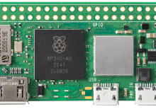
The Raspberry Pi Zero 2 W is a compact and powerful single-board computer designed for various applications, from IoT projects to educational tools. It combines the small form factor of the original Raspberry Pi Zero with significant performance improvements, making it an ideal choice for projects requiring both compact size and computing power. The Zero 2 W features a quad-core ARM Cortex-A53 CPU, offering a balance of efficiency and capability.
Key Features:
- Processor: Broadcom BCM2710A1, quad-core 64-bit ARM Cortex-A53
- Clock Speed: 1 GHz
- RAM: 512 MB LPDDR2 SDRAM
- Wireless:
- 802.11 b/g/n wireless LAN
- Bluetooth 4.2
- Bluetooth Low Energy (BLE)
- Connectivity:
- 1x Mini HDMI port
- 2x Micro USB ports (1 for power, 1 for data)
- 1x Micro USB On-The-Go (OTG) port
- 1x MicroSD card slot
- HAT-compatible 40-pin header
- Composite video and reset headers
- Power: 5V, 2.5A power via micro USB
- Operating System: Compatible with Raspberry Pi OS and other Linux-based systems
Technical Specifications:
- Dimensions: 65 mm x 30 mm x 5 mm
- Weight: Approximately 9 g
- GPU: VideoCore IV, capable of 1080p60 H.264 decode
- Power Consumption: Typically around 0.5W to 1W
- Operating Temperature: 0°C to +50°C
- GPIO: 40-pin GPIO header, identical pinout to Model A+/B+/2B/3B/4B
- Video Output: Mini HDMI for 1080p output
- Audio Output: HDMI and composite
Applications:
- IoT Projects: Ideal for Internet of Things (IoT) applications due to its small size and wireless capabilities.
- Education: Used in classrooms for teaching programming and electronics.
- Prototyping: Suitable for developing and testing electronic projects.
- Embedded Systems: Perfect for integrating into custom embedded systems and devices.
- Media Center: Can be used to create a compact and affordable media center.
Datasheet:
For detailed technical information, refer to the Raspberry Pi Zero 2 W Datasheet.
|
