|
Description |
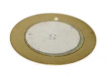
The Piezoelectric Transducer 27mm is a compact and efficient device used for converting electrical signals into mechanical vibrations or sound waves. It is commonly used in buzzers, alarms, and ultrasonic applications due to its ability to generate precise and high-frequency sounds. The transducer is highly reliable, lightweight, and suitable for various electronic projects and devices.
Key Features:
- High Sensitivity: Efficiently converts electrical energy into mechanical vibrations.
- Compact Size: 27mm diameter, suitable for space-constrained applications.
- Wide Frequency Range: Capable of generating a broad range of frequencies.
- Low Power Consumption: Operates efficiently with minimal power.
- Durable Construction: Designed for long-lasting performance.
- Easy Integration: Simple to integrate into various circuits and devices.
Technical Specifications:
- Diameter: 27mm
- Resonant Frequency: Typically around 4 kHz (varies by model)
- Capacitance: Typically 2000 pF at 1 kHz (varies by model)
- Operating Voltage: 3V to 30V (varies by model)
- Sound Pressure Level: Typically 85 dB at 10 cm and 5V (varies by model)
- Operating Temperature Range: -20°C to +60°C
- Material: Metal and ceramic
Applications:
- Buzzers and Alarms: Used in buzzers, alarms, and warning systems.
- Ultrasonic Cleaners: Integrated into ultrasonic cleaning devices.
- Medical Devices: Utilized in medical equipment for ultrasonic applications.
- Sonar Systems: Employed in sonar systems for underwater detection.
- Musical Instruments: Used in electronic musical instruments for sound generation.
- DIY Projects: Suitable for hobbyist and educational electronic projects.
Usage:
- Wiring: Connect the transducer to the appropriate points in your circuit, typically using driver circuits to control the input signal.
- Power Supply: Ensure the transducer is supplied with the correct voltage to prevent damage.
- Mounting: Secure the transducer in place within your device, ensuring it has sufficient space to vibrate freely.
- Testing: Test the transducer by applying the input signal and verifying the sound output or vibration.
Caution:
- Handling: Handle with care to avoid damage to the ceramic element.
- Voltage: Ensure correct voltage levels to avoid overloading the transducer.
- Environmental Conditions: Use within the specified temperature range to maintain performance.
Datasheet:
For detailed technical specifications, refer to the Piezoelectric Transducer 27mm Datasheet.
|
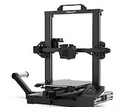
The Creality CR-6SE is a high-precision 3D printer designed for users seeking reliable, professional-quality prints. Known for its ease of use and innovative features, the CR-6SE offers an enhanced printing experience with a focus on accuracy, stability, and user convenience. Ideal for hobbyists, educators, and professionals, this 3D printer delivers excellent performance for a variety of projects, from prototypes to complex models.
Key Features:
- High Precision Printing: Delivers detailed and accurate prints with a layer resolution of 0.1 mm.
- Auto-Leveling System: Features an advanced leveling-free system for hassle-free setup.
- Silent Operation: Equipped with a silent motherboard and TMC2209 drivers for quiet printing.
- Sturdy Construction: Built with a robust aluminum frame for stability and durability.
- Modular Design: Easy to assemble and maintain with a modular design.
- Resume Printing Function: Capable of resuming printing after power outages or interruptions.
- Touch Screen Interface: 4.3-inch color touch screen for an intuitive user interface.
- Dual Z-Axis: Provides improved accuracy and stability for the Z-axis movement.
Technical Specifications:
- Build Volume: 235 x 235 x 250 mm
- Layer Resolution: 0.1 mm
- Printing Speed: Up to 100 mm/s
- Nozzle Diameter: Standard 0.4 mm (interchangeable)
- Filament Compatibility: PLA, ABS, TPU, PETG, and other 1.75 mm filaments
- Extruder Type: Single Bowden extruder
- Print Bed: Carborundum glass platform for better adhesion and easy removal of prints
- Connectivity: USB, SD card
- Operating Temperature: Nozzle: Up to 260°C, Bed: Up to 110°C
- Power Supply: Meanwell 24V 350W
Applications:
- Prototyping: Ideal for creating accurate and detailed prototypes.
- Education: Useful for educational purposes in schools and universities.
- Art and Design: Perfect for artists and designers creating intricate models.
- DIY Projects: Suitable for hobbyists and makers working on custom projects.
- Manufacturing: Can be used for small-scale manufacturing and production of parts.
Usage:
- Assembly: Follow the provided instructions to assemble the 3D printer.
- Leveling: Use the auto-leveling system to ensure the print bed is properly leveled.
- Loading Filament: Load the desired filament into the extruder.
- Printing: Upload the 3D model via USB or SD card and start the print job using the touch screen interface.
- Post-Processing: Remove the finished print from the bed and perform any necessary post-processing.
Caution:
- Safety: Always operate the printer in a well-ventilated area.
- Temperature: Handle heated components with care to avoid burns.
- Maintenance: Regularly clean and maintain the printer for optimal performance.
Datasheet:
For detailed technical specifications, refer to the Creality CR-6SE Datasheet.
|
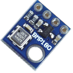
The BMP180 is a high-precision digital barometer and altitude sensor from Bosch, designed to measure atmospheric pressure and temperature. It is commonly used in applications requiring accurate altitude measurement and weather monitoring. The BMP180 provides reliable data for various applications including GPS, weather stations, and altitude tracking in wearable devices.
Key Features:
- Accurate barometric pressure and temperature measurement
- Digital interface with I²C or SPI communication
- High resolution with 0.03 hPa pressure measurement accuracy
- Compact and low-power design
- Built-in calibration for precise readings
- Wide operating temperature range
Technical Specifications:
- Sensor Type: Barometric Pressure and Temperature Sensor
- Communication Protocol: I²C (default), SPI (optional)
- Pressure Range: 300 hPa to 1100 hPa
- Pressure Accuracy: ±1 hPa (typical)
- Temperature Range: -40°C to +85°C
- Temperature Accuracy: ±1°C
- Resolution: 0.03 hPa for pressure
- Operating Voltage: 1.8V to 3.6V
- Current Consumption: 3µA (typical in sleep mode), 10µA (typical in measurement mode)
- Package Type: LGA-8 (Leadless Grid Array)
Applications:
- Altitude and weather tracking
- GPS altitude calibration
- Pressure-based data logging
- Environmental monitoring
- Wearable devices and consumer electronics
Usage:
- Connect the BMP180 sensor to your microcontroller or development board using I²C or SPI interface.
- Power the sensor with a voltage within the operating range (1.8V to 3.6V).
- Use the appropriate library or driver for the I²C or SPI protocol to interface with the sensor.
- Retrieve and process pressure and temperature data according to your application needs.
Caution:
- Ensure proper voltage supply to avoid damage to the sensor.
- Handle the sensor carefully to prevent mechanical damage or contamination.
- Verify correct wiring and communication protocol settings for accurate readings.
Datasheet:
For detailed technical specifications, refer to the BMP180 Datasheet.
|
A line tracking sensor is an infrared-based module used for detecting and following lines or paths on surfaces. It is commonly employed in robotics and automated systems to navigate predefined routes or tracks.
Key Features:
- Sensor Type: Infrared (IR) sensor module.
- Detection Method: Typically uses infrared light emitted by LEDs and reflected off the surface.
- Detection Capability: Can detect lines of contrasting colors (typically black on white or vice versa).
- Output: Digital signals indicating line detection (e.g., high or low) or analog signals proportional to the position on the line.
- Operating Voltage: Usually operates at 5V DC.
- Adjustability: Often adjustable sensitivity to fine-tune detection based on line width and surface reflectivity.
- Integration: Compact and designed for easy integration into robotic systems or line-following vehicles.
- Mounting: Typically includes mounting holes or brackets for easy installation.
Technical Specifications:
- Dimensions: Compact size suitable for various robotic applications.
- Operating Range: Suitable for indoor and controlled outdoor environments.
- Response Time: Fast response to changes in line position.
- Operating Temperature: Typically -10°C to +50°C.
Applications:
- Automated guided vehicles (AGVs)
- Line-following robots
- Industrial automation
- Educational robotics projects
Datasheet: For detailed technical information, refer to the Line Tracking Sensor datasheet.
|
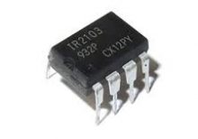
The IR2103PBF is a high voltage, high-speed power MOSFET and IGBT driver with independent high and low side referenced output channels. It is designed to drive high-side and low-side N-channel power MOSFETs or IGBTs in a half-bridge configuration. The device features a floating channel designed for bootstrap operation, allowing it to drive the high-side switch up to 600V.
Key Features:
- Gate drive supply range from 10V to 20V
- Floating channel can be used to drive an N-channel power MOSFET or IGBT in the high-side configuration up to 600V
- Gate drive outputs: 2A peak source, 2A peak sink
- Independent high-side and low-side channels
- Under-voltage lockout for both channels
- Logic input (IR2103) compatible with standard CMOS or LSTTL outputs
- Matched propagation delay for both channels
- Low side output in phase with input signal
- High side output out of phase with input signal
Technical Specifications:
- Supply Voltage (Vcc): 10V – 20V
- Floating Supply Voltage (Vb): up to 600V
- Logic Supply Voltage (Vss): -5V – 20V
- Output Source Current (Io+): 2A
- Output Sink Current (Io-): 2A
- Gate Drive Output Voltage (Vout): 10V – 20V
- Propagation Delay: 120ns (typical)
- Operating Temperature Range: -40°C to +125°C
- Package: PDIP-8
Applications:
- Motor drive applications
- Induction heating
- UPS systems
- DC-DC converters
- Switch-mode power supplies
Datasheet:
For detailed technical information, please refer to the IR2103PBF Datasheet.
|
The STM8S Development Board is a comprehensive platform designed for developing and prototyping with the STM8S series microcontrollers. It provides a robust set of features and peripherals to facilitate a wide range of applications, from simple embedded projects to complex industrial control systems. The board offers easy access to all the microcontroller’s functionalities and includes a variety of interfaces and connectors to enhance development efficiency.
Key Features:
- Microcontroller: Based on the STM8S series microcontroller.
- Peripheral Interfaces: Multiple GPIOs, UART, I2C, SPI, and ADC/DAC interfaces.
- Power Supply Options: Supports multiple power supply options, including USB and external sources.
- On-Board Debugging: Integrated SWIM interface for debugging and programming.
- Expandable: Pin headers for easy expansion with additional modules and shields.
- User-Friendly Design: Includes user LEDs, push buttons, and a reset button for easy development and testing.
- Software Support: Compatible with various IDEs and development tools, including STM8S firmware libraries.
Technical Specifications:
- Microcontroller: STM8S series
- Operating Voltage: 3.3V to 5V
- Communication Interfaces: UART, I2C, SPI
- Analog Inputs: Multiple ADC channels
- Digital I/O: Multiple GPIO pins
- Clock Speed: Up to 16MHz
- Memory: Flash, RAM, and EEPROM (varies by specific STM8S model)
- Dimensions: Compact and portable design
Applications:
- Embedded Systems: Ideal for developing and prototyping embedded systems.
- Industrial Control: Suitable for industrial automation and control applications.
- Education and Training: Perfect for educational purposes and hands-on learning.
- Home Automation: Can be used in home automation projects.
- Consumer Electronics: Applicable in various consumer electronic devices.
Datasheet:
For detailed technical specifications, refer to the STM8S Development Board Datasheet.
|
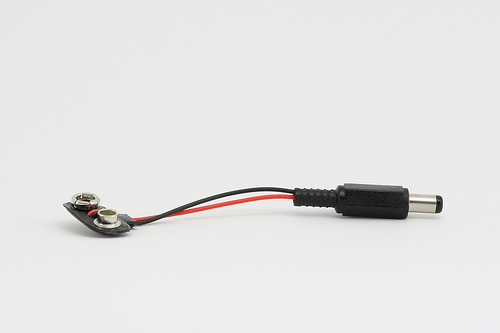
The Arduino 9V Battery Connector is a convenient accessory for powering Arduino boards and other compatible devices. It allows you to connect a standard 9V battery to the Arduino’s power jack, providing a portable power solution for your projects. This connector is essential for mobile and battery-operated applications, offering an easy and reliable way to supply power to your electronics.
Key Features:
- Compatible with standard 9V batteries
- Easy to connect and use
- Provides a secure and stable power connection
- Compact and portable design
- Durable construction for long-lasting use
- Standard DC barrel plug compatible with Arduino boards
Technical Specifications:
- Connector Type: DC barrel plug (center-positive)
- Barrel Plug Dimensions: Outer diameter 5.5mm, inner diameter 2.1mm
- Battery Connector Type: Snap-on connector for 9V battery
- Cable Length: Approximately 15 cm
- Material: Plastic and metal connectors with insulated wire
- Color: Typically black with red and black wires
Applications:
- Portable Arduino projects
- Battery-operated electronics
- Prototyping and testing
- Educational kits
- DIY electronics
Usage:
- Connection:
- Snap the 9V battery connector onto the terminals of a standard 9V battery.
- Insert the DC barrel plug into the power jack of your Arduino board or compatible device.
- Powering:
- Ensure the polarity of the connections is correct (center-positive) to avoid damage to the board.
- The Arduino will draw power from the 9V battery through the connector.
- Monitoring:
- Monitor the battery voltage periodically to ensure it remains within the acceptable range for your Arduino board (typically 7-12V).
Caution:
- Ensure the connector is securely attached to the battery terminals to prevent intermittent connections.
- Avoid short-circuiting the battery terminals.
- Do not expose the connector to moisture or extreme temperatures.
- Remove the battery from the connector when not in use to prevent battery drain.
Datasheet:
Refer to the manufacturer’s guidelines or specifications for further details.
|
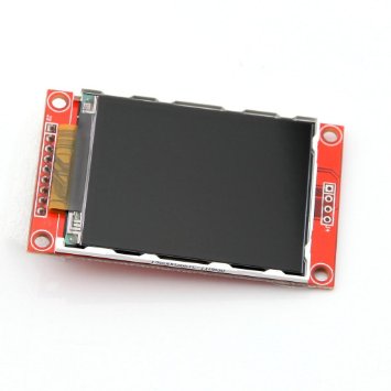
The 2.2-inch colored LCD is a compact display module designed to provide clear and vibrant visual output in a small form factor. This LCD module is ideal for various embedded applications where space is limited but a color display is required. It is commonly used in consumer electronics, handheld devices, and development projects.
Key Features:
- 2.2-inch TFT LCD display
- High-resolution color display for clear and vibrant visuals
- Wide viewing angle for better visibility from different perspectives
- Supports multiple color formats (RGB)
- Easy integration with microcontrollers and development boards
- Low power consumption for efficient operation
- Durable and compact design
Technical Specifications:
- Display Type: TFT LCD
- Screen Size: 2.2 inches
- Resolution: 240 x 320 pixels
- Color Depth: 65K colors (16-bit RGB)
- Interface: SPI, parallel (depends on model)
- Operating Voltage: 3.3V to 5V
- Backlight: LED
- Viewing Angle: 160° horizontal/vertical (varies by model)
- Dimensions: Varies by manufacturer (common size: 50mm x 60mm x 6mm)
- Weight: Varies by manufacturer (typically around 25g)
Applications:
- Portable electronic devices
- Handheld gadgets and consumer electronics
- Industrial control displays
- Educational projects and prototyping
- Home automation systems
Usage:
- Connect the LCD module to your microcontroller or development board using the appropriate interface (SPI, parallel).
- Power the module with a compatible power source (3.3V to 5V).
- Install and configure the necessary display libraries and drivers for your development environment.
- Use the provided functions to initialize the display and send data for visualization.
- Customize the display output according to your project requirements.
Caution:
- Handle the LCD module with care to avoid damage to the screen or connectors.
- Ensure correct wiring and voltage levels to prevent electrical damage.
- Follow the manufacturer’s guidelines for installation and operation to avoid damage and ensure proper functionality.
Datasheet:
For detailed technical specifications, refer to the 2.2-Inch Colored LCD Datasheet.
|
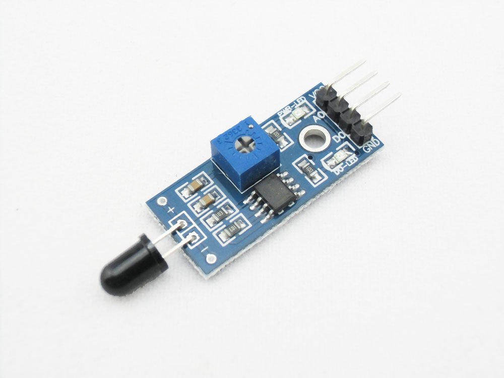
A flame sensor is an infrared (IR) detector used to detect the presence of flame or fire. It is typically used in fire detection and safety systems to provide early warning and activate safety measures. The sensor is sensitive to IR light emitted by flames and can be used in various applications, including security systems, fire-fighting robots, and automatic fire alarm systems.
Key Features:
- Detects infrared light emitted by flames
- High sensitivity and fast response time
- Analog and digital output signals
- Adjustable sensitivity via potentiometer
- Compact and easy to integrate into various systems
- Onboard indicator LED for detection status
Technical Specifications:
- Detection Range: Up to 100cm (varies by model and flame size)
- Wavelength Range: 760nm to 1100nm (IR spectrum)
- Operating Voltage: 3.3V to 5V
- Output Type: Digital (DO) and Analog (AO)
- Response Time: Typically less than 100ms
- Dimensions: Typically around 32mm x 14mm x 8mm (varies by manufacturer)
- Operating Temperature Range: -25°C to +85°C
Applications:
- Fire detection systems
- Security and alarm systems
- Fire-fighting robots
- Industrial safety systems
- Household safety devices
- DIY electronics projects
Usage:
- Connect the flame sensor to your microcontroller or development board, ensuring proper connection of the power supply (VCC, GND) and the output pins (DO, AO).
- Use the digital output (DO) to detect the presence of flame with a simple HIGH/LOW signal.
- Use the analog output (AO) to get a proportional value indicating the intensity of the detected flame.
- Adjust the sensitivity of the sensor using the onboard potentiometer if necessary.
- Implement code to monitor the sensor outputs and trigger appropriate actions or alarms when a flame is detected.
Caution:
- Ensure the sensor is correctly oriented and positioned to detect the flame source accurately.
- Avoid exposing the sensor to direct sunlight or strong artificial light to prevent false detections.
- Handle the sensor carefully to avoid damage to the sensitive IR components.
Datasheet:
For detailed technical specifications, refer to the specific product datasheet provided by the manufacturer.
|
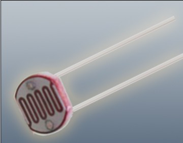
The Photoresistor LDR (Light Dependent Resistor) is a variable resistor whose resistance changes with the light intensity that falls upon it. It is widely used in light sensing applications and projects where detecting light levels is essential. LDRs are cost-effective, easy to use, and suitable for various electronic projects, including light meters, street lights, and other light-sensitive devices.
Key Features:
- Light Sensitivity: Resistance decreases with increasing light intensity
- Simple Interface: Easy to integrate with microcontrollers and analog circuits
- Low Cost: Economical solution for light detection
- Wide Range of Light Detection: Can detect various light levels from low to high intensity
- Compact Size: Fits easily into small projects
Technical Specifications:
- Resistance in Darkness: Typically 1MΩ (depending on specific model)
- Resistance in Bright Light: Typically 10-20kΩ (depending on specific model)
- Spectral Peak: Approximately 540nm (most sensitive to green light)
- Response Time: Rise time ~20ms, fall time ~30ms
- Operating Temperature Range: -30°C to +70°C
- Diameter: Typically 5mm to 10mm (depending on specific model)
Applications:
- Light Meters: Measure light intensity for photography and scientific applications.
- Street Lights: Automatic on/off control based on ambient light levels.
- Alarm Systems: Detect changes in light levels for security purposes.
- Consumer Electronics: Light-sensitive control in devices like clocks and displays.
- Educational Projects: Common component in learning modules for electronics.
Usage:
- Circuit Integration: Connect the LDR in a voltage divider circuit with a fixed resistor to create a variable voltage output based on light intensity.
- Microcontroller Interface: Read the voltage output from the LDR circuit using an analog input pin on a microcontroller.
- Programming: Write code to interpret the analog signal and perform actions based on light levels (e.g., turning on an LED when it gets dark).
- Testing: Calibrate the LDR circuit for the desired light sensitivity by adjusting the fixed resistor value.
Caution:
- Environment: Avoid exposure to extreme temperatures and humidity, which may affect the LDR’s performance.
- Handling: Handle with care to avoid damaging the sensitive surface of the LDR.
Datasheet:
For detailed technical specifications, refer to the Photoresistor LDR Datasheet.
|
The T Plug Pair, also known as Deans connectors, is a set of high-current connectors commonly used in RC models, batteries, and other electronic applications requiring reliable and secure power connections. These connectors are known for their low resistance, high current carrying capacity, and easy-to-use design.
Key Features:
- Type: T Plug (Deans connectors)
- Current Capacity: High current capacity for demanding applications
- Design: Compact design for ease of use and installation
- Material: High-quality plastic housing with gold-plated metal contacts for improved conductivity and durability
- Polarity: Clearly marked to prevent incorrect connections
- Compatibility: Widely compatible with RC batteries, ESCs, and other electronic devices
Technical Specifications:
- Dimensions:
- Length: Approximately 15 mm
- Width: Approximately 8 mm
- Height: Approximately 20 mm
- Weight: Approximately 2-3 g per connector
- Material:
- Contacts: Gold-plated for low resistance and high conductivity
- Housing: Heat-resistant plastic
- Current Rating: Up to 60A continuous (varies by manufacturer)
- Voltage Rating: Typically up to 20V
- Connection Type: Soldered connections for secure attachment to wires
Applications:
- RC Models: Commonly used in RC cars, boats, airplanes, and drones for connecting batteries to ESCs and motors.
- Batteries: Ideal for making secure connections between batteries and electronic devices.
- DIY Electronics: Useful for hobbyists and engineers working on custom electronic projects requiring reliable power connections.
- Power Systems: Suitable for high-current applications in various power systems and electronic setups.
Datasheet:
For detailed technical information, refer to the T Plug Pair Datasheet.
|
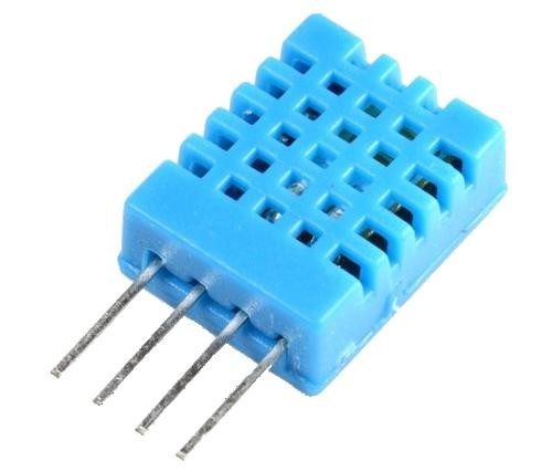
The DHT11 is a basic, ultra-low-cost digital temperature and humidity sensor. It uses a capacitive humidity sensor and a thermistor to measure the surrounding air and outputs a digital signal on the data pin. It’s simple to use but requires careful timing to grab data. It’s perfect for DIY projects, weather stations, and other applications where accurate and reliable temperature and humidity readings are needed.
Key Features:
- Temperature Range: 0-50°C with ±2°C accuracy
- Humidity Range: 20-80% RH with ±5% RH accuracy
- Low Power Consumption: Efficient for battery-operated applications
- Single Wire Digital Interface: Easy to interface with microcontrollers
- Pre-calibrated: No need for additional calibration
- Compact Size: Suitable for compact projects and devices
Technical Specifications:
- Temperature Range: 0-50°C (32-122°F)
- Humidity Range: 20-80% RH
- Temperature Accuracy: ±2°C
- Humidity Accuracy: ±5% RH
- Operating Voltage: 3.3V to 5.5V
- Max Current: 2.5mA
- Output: Digital signal via 1-wire protocol
- Dimensions: 15.5mm x 12mm x 5.5mm
Applications:
- Weather Stations: Monitor and log temperature and humidity levels.
- Home Automation: Control HVAC systems based on environmental conditions.
- Greenhouses: Maintain optimal growing conditions for plants.
- DIY Projects: Perfect for hobbyists building custom sensors and gadgets.
- Data Loggers: Record environmental data over time for analysis.
- Educational Projects: Teach students about sensors and data acquisition.
Usage:
- Wiring: Connect the VCC pin to 3.3V or 5V, GND to ground, and the DATA pin to a digital input on your microcontroller.
- Library Integration: Use libraries available for platforms like Arduino or Raspberry Pi to simplify reading data from the sensor.
- Coding: Write code to initialize the sensor and read temperature and humidity data.
- Data Processing: Process and use the sensor data in your application as needed, such as displaying it on an LCD or sending it to a web server.
Caution:
- Power Supply: Ensure the sensor is supplied with the correct voltage to avoid damage.
- Environmental Conditions: Keep the sensor in a dust-free, non-condensing environment for accurate readings.
- Wiring Length: Minimize the length of wiring between the sensor and the microcontroller to maintain signal integrity.
Datasheet:
For detailed technical specifications, refer to the DHT11 Datasheet.
|
The PIC12F675 is an 8-bit microcontroller from Microchip’s PIC12 family, known for its low-power operation and compact size. It is designed for applications requiring a small form factor and includes integrated peripherals like timers and an Analog-to-Digital Converter (ADC), making it suitable for simple control tasks and sensor interfacing.
Key Features:
- 8-bit microcontroller with 14-bit instruction set architecture
- 128 bytes of RAM
- 256 bytes of EEPROM
- 10-bit Analog-to-Digital Converter (ADC)
- Two Timer modules (Timer0 and Timer1)
- Watchdog Timer (WDT)
- Capture/Compare/PWM (CCP) module
- Low-power operation with multiple sleep modes
- 6-bit wide I/O ports
- Internal oscillator
Technical Specifications:
- Operating Voltage: 2.0V to 5.5V
- Operating Frequency: Up to 20MHz
- Program Memory Size: 1KB (Flash)
- Data Memory Size: 64 bytes SRAM
- EEPROM Size: 128 bytes
- Number of I/O Pins: 6
- Timers: 8-bit Timer0, 8-bit Timer1
- ADC Resolution: 10-bit
- Package Type: 8-pin PDIP, 8-pin SOIC
Applications:
- Consumer electronics
- Battery-operated devices
- Simple sensor interfacing
- LED and display control
- Remote controls
- Low-power embedded systems
Usage:
- Connect the microcontroller to a power supply within the recommended voltage range.
- Program the PIC12F675 using its Flash program memory for specific tasks.
- Utilize the ADC for analog signal processing and Timer modules for timing tasks.
- Manage power consumption effectively using sleep modes for battery-operated applications.
Caution:
- Check power supply and connections to prevent damage.
- Handle with care to avoid electrostatic discharge (ESD) damage.
- Ensure I/O pins do not exceed maximum current ratings to prevent damage.
Datasheet:
For detailed technical specifications, refer to the PIC12F675 Datasheet.
|
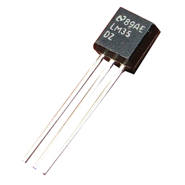
The LM35 is a precision temperature sensor with an analog output proportional to the temperature in degrees Celsius. This sensor offers high accuracy and linearity, making it ideal for a wide range of temperature measurement applications in both commercial and industrial environments. The LM35 does not require any external calibration or trimming, simplifying its use in embedded systems and temperature monitoring solutions.
Key Features:
- Type: Analog temperature sensor
- Accuracy: ±0.5°C at room temperature
- Range: -55°C to +150°C
- Linear Output: 10mV/°C
- Low Self-Heating: Less than 0.1°C in still air
- Wide Operating Voltage: 4V to 30V
- Low Impedance Output: Can drive up to 1mA load
- Calibration: Factory calibrated in Celsius
Technical Specifications:
- Output Voltage: 10mV per °C
- Operating Voltage: 4V to 30V
- Temperature Range: -55°C to +150°C
- Accuracy: ±0.5°C at 25°C
- Self-Heating: 0.08°C in still air
- Response Time: 1.5 seconds (typical)
- Output Impedance: Low impedance output (less than 1 ohm)
- Package Type: TO-92, SO-8, TO-220
Applications:
- Temperature Measurement: Suitable for HVAC systems, environmental monitoring, and home appliances.
- Thermal Protection: Can be used for thermal shutdown and temperature control in electronic devices.
- Industrial Equipment: Monitoring temperature in industrial machinery and processes.
- Consumer Electronics: Used in gadgets, computers, and other electronic products for temperature sensing.
- Automotive: Temperature monitoring in automotive systems and engines.
Usage:
- Circuit Integration: Connect the LM35 sensor to a microcontroller or analog-to-digital converter (ADC) to read temperature data.
- Power Supply: Provide a stable voltage within the operating range (4V to 30V).
- Temperature Reading: Measure the output voltage, which corresponds to the temperature (e.g., 250mV equals 25°C).
Caution:
- Proper Wiring: Ensure correct wiring to avoid damage to the sensor.
- Environment: Protect the sensor from extreme conditions beyond its specified range.
Datasheet:
For detailed technical specifications, refer to the LM35 Temperature Sensor Datasheet.
|
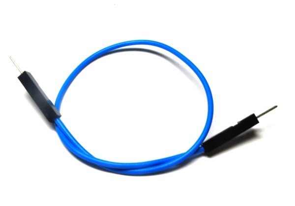
A single male-male jumper wire features male connectors on both ends and is used for making connections between components, breadboards, and other circuit boards. These wires are essential in prototyping and development for creating temporary circuits or testing designs. They allow for easy and flexible connections without the need for soldering.
Key Features:
- Connectors: Male connectors on both ends
- Wire Type: Flexible, insulated wire for easy handling and routing
- Length: Available in various lengths to suit different project needs
- Color-Coded: Available in multiple colors for easy identification and organization
- Durability: Made from high-quality materials for reliable and repeated use
- Compatibility: Suitable for standard 2.54mm (0.1 inch) pitch headers and connectors
Technical Specifications:
- Connector Type: Male-to-male
- Wire Gauge: Typically 28 AWG
- Insulation Material: PVC or similar flexible plastic
- Pitch: 2.54mm (0.1 inch)
- Length Options: Common lengths include 10cm, 20cm, 30cm, and others
- Operating Temperature: Typically -40°C to +80°C
- Current Rating: Usually up to 1A
Applications:
- Prototyping: Ideal for making connections on breadboards and development boards.
- Educational Projects: Used in educational settings to teach electronics and programming concepts.
- DIY Electronics: Suitable for hobbyists and makers working on various electronics projects and experiments.
- Temporary Connections: Useful for creating temporary connections during development and testing.
- Interfacing Components: Facilitates connections between components and modules with male pin headers.
|
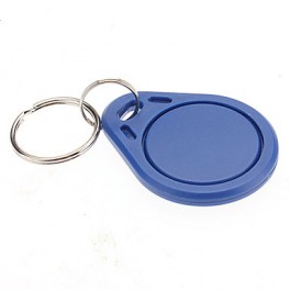
The 125KHZ RFID Key Chain is a compact and durable radio-frequency identification (RFID) device used for access control and identification applications. It operates at a frequency of 125kHz and is compatible with standard RFID readers. The key chain format makes it convenient to carry and use for various applications such as security systems, attendance tracking, and asset management.
Key Features:
- Operates at 125kHz frequency
- Durable and compact key chain design
- Compatible with standard RFID readers
- Unique identification number (UID) for each key chain
- Waterproof and shock-resistant
- Long read range (up to 10 cm depending on the reader)
- No battery required (passive RFID technology)
Technical Specifications:
- Operating Frequency: 125kHz
- Material: ABS plastic
- Dimensions: Approximately 40mm x 32mm x 4mm
- Weight: Approximately 6g
- Read Range: Up to 10 cm (depending on the reader and environment)
- Data Storage: 64-bit read-only unique identifier (UID)
- Operating Temperature Range: -25°C to +85°C
- Color: Typically blue, but may vary by manufacturer
- Waterproof: Yes
Applications:
- Access control systems
- Time and attendance tracking
- Membership management
- Asset tracking
- Secure entry systems
- Contactless payment systems
Usage:
- Integration:
- Enroll the RFID key chain in the desired RFID system by registering its unique identifier (UID) with the system’s database.
- Operation:
- Present the key chain to an RFID reader within the read range (up to 10 cm).
- The reader will capture the UID and communicate it to the control system for processing.
- Security:
- Use the key chain for secure access to restricted areas or for tracking attendance.
- Pair the key chain with a compatible RFID reader and control system for seamless operation.
Caution:
- Avoid exposing the key chain to extreme temperatures or harsh chemicals.
- Do not bend or apply excessive force to the key chain to prevent damage.
- Keep the key chain away from strong magnetic fields to ensure proper operation.
Datasheet:
For detailed technical specifications, refer to the manufacturer’s datasheet for your specific 125kHz RFID key chain model.
|
Description:
The ULINK2 Debug Adapter is a versatile tool designed for debugging and programming ARM Cortex-M based microcontrollers. It connects a host computer with ARM processors via USB, facilitating real-time debugging, flash programming, and system analysis. The ULINK2 adapter supports various ARM cores and integrates seamlessly with Keil MDK (Microcontroller Development Kit) for efficient development and testing of embedded systems.
Key Features:
- USB interface for connectivity with host computer
- Supports ARM Cortex-M series microcontrollers
- Real-time debugging capabilities
- Flash programming for on-chip memory
- System analysis with event- and cycle-accurate tracing
- Integrated support for Keil MDK IDE
- Compatible with various ARM development boards and evaluation platforms
Technical Specifications:
- Interface: USB 2.0
- Supported Cores: ARM Cortex-M0, M0+, M3, M4, M7
- Debug Protocols: JTAG, SWD (Serial Wire Debug)
- Programming: Flash programming for on-chip memory
- Operating System Compatibility: Windows
- Dimensions: Compact and portable design
Applications:
- Embedded software development
- Firmware debugging
- System optimization and analysis
- Educational purposes in ARM microcontroller programming
- Integration with ARM development environments
Datasheet:
For detailed technical information, refer to the Datasheet.
|
The PICkit 3 with ZIF Adapter is a programmer and debugger tool designed for use with Microchip’s PIC microcontrollers and dsPIC Digital Signal Controllers (DSCs). The PICkit 3 offers an easy and reliable way to program and debug PIC microcontrollers directly from the MPLAB IDE software. The included ZIF (Zero Insertion Force) adapter enhances the usability by providing a convenient and secure way to insert and remove microcontroller chips without damaging the pins, making it ideal for frequent programming and development tasks.
Key Features:
- Supports a wide range of PIC microcontrollers and dsPIC DSCs
- Direct connection to the MPLAB IDE software for programming and debugging
- USB connectivity for easy interface with a computer
- Real-time execution and debugging capabilities
- Integrated ZIF adapter for easy chip insertion and removal
- Compact and portable design
Technical Specifications:
- Programmer Type: In-Circuit Debugger (ICD) and Programmer
- Connectivity: USB 2.0 interface
- Supported Devices: Wide range of PIC microcontrollers and dsPIC DSCs
- Programming Voltage: 2.0V to 5.5V
- Debugging Features: Real-time execution, breakpoints, single-step, and variable inspection
- ZIF Adapter: 28-pin socket for easy insertion and removal of chips
- Dimensions: Typically 95mm x 62mm x 25mm (programmer), 80mm x 30mm x 20mm (ZIF adapter)
Applications:
- Development and prototyping with PIC microcontrollers
- Educational purposes and learning about microcontroller programming
- Firmware debugging and testing
- Programming PIC microcontrollers for embedded systems and projects
Usage:
- Connect the PICkit 3 to your computer via the USB cable.
- Install the necessary drivers and MPLAB IDE software from Microchip’s website.
- Insert the PIC microcontroller into the ZIF adapter, ensuring correct orientation.
- Connect the ZIF adapter to the PICkit 3 programmer.
- Open the MPLAB IDE software and configure the programmer settings.
- Program and debug your PIC microcontroller using the MPLAB IDE interface.
Caution:
- Ensure correct orientation of the microcontroller in the ZIF adapter to avoid damaging the pins.
- Follow the recommended voltage levels and programming guidelines provided by Microchip.
- Handle the PICkit 3 and ZIF adapter carefully to prevent static discharge and physical damage.
Datasheet:
For detailed technical specifications, refer to the PICkit 3 with ZIF Adapter Datasheet.
|
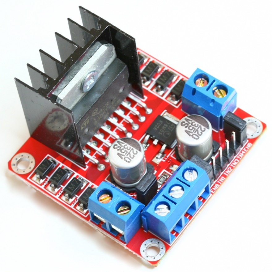
The L298N Dual H Bridge DC Stepper Motor Driver is a robust and versatile module used for controlling DC and stepper motors in various electronic projects. This driver module can control the speed and direction of two DC motors or a single stepper motor, making it ideal for robotics, automation, and other motor control applications. It features an onboard 5V regulator and can handle high currents, ensuring reliable operation in demanding environments.
Key Features:
- Motor Control: Dual H Bridge for controlling two DC motors or one stepper motor
- Voltage Range: Supports motor voltage from 5V to 35V
- Current Handling: Each bridge can handle up to 2A
- Onboard 5V Regulator: Provides 5V output for powering external circuits
- Control Pins: Enable and direction control for each motor
- Protection: Built-in thermal shutdown and overcurrent protection
- Compact Design: Easy to integrate into various projects
Technical Specifications:
- Motor Voltage: 5V to 35V
- Current Handling: 2A per bridge (peak 3A)
- Logic Voltage: 5V
- Control Inputs: 4 (IN1, IN2, IN3, IN4) for direction control
- Enable Pins: 2 (EN1, EN2) for enabling the motors
- Output Voltage: 5V (when using onboard regulator)
- Dimensions: 43mm x 43mm x 27mm
Applications:
- Robotics: Control of DC motors and stepper motors in robots.
- Automation: Use in automated systems for precise motor control.
- DIY Projects: Ideal for hobbyists and makers building motorized projects.
- Industrial Control: Suitable for controlling motors in industrial equipment.
- Educational Kits: Commonly used in learning modules for motor control.
Usage:
- Power Supply: Connect the motor power supply to the VCC and GND terminals, ensuring it is within the specified voltage range.
- Motor Connection: Connect the DC motors or stepper motor to the output terminals (OUT1, OUT2, OUT3, OUT4).
- Control Inputs: Use the control pins (IN1, IN2, IN3, IN4) to set the direction of the motors. The enable pins (EN1, EN2) can be used to enable or disable the motors.
- Logic Power: If using the onboard 5V regulator, connect the 5V and GND pins to your microcontroller or control circuit.
- Programming: Write code to control the motor speed and direction using PWM signals and logic inputs.
Caution:
- Heat Dissipation: The module can get hot during operation. Use a heat sink or cooling fan if necessary.
- Voltage and Current Limits: Do not exceed the specified voltage and current ratings to prevent damage.
Datasheet:
For detailed technical specifications, refer to the L298N Dual H Bridge DC Stepper Motor Driver Datasheet.
|
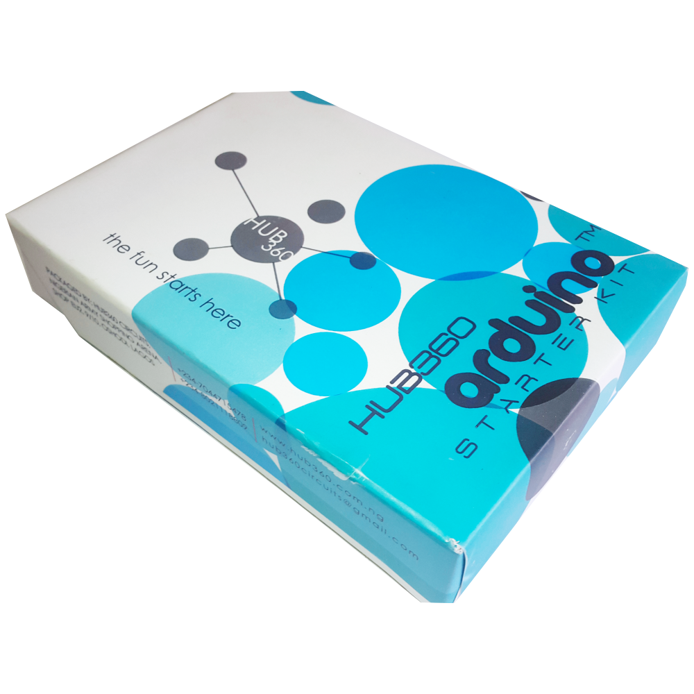
The Hub360 Arduino Starter Kit is a comprehensive package designed for beginners and enthusiasts looking to dive into the world of electronics and programming. This kit includes Arduino Uno, which is a microcontroller board based on the ATmega328P. The kit provides a variety of components and modules to help users learn and experiment with different electronic projects and concepts.
Key Features:
- Includes Arduino Uno board
- Comprehensive set of components and modules for various projects
- Ideal for beginners and hobbyists
- Detailed tutorial and project guide included
- USB interface for easy programming and power
- Compatible with Arduino IDE and various libraries
Technical Specifications:
- Microcontroller: ATmega328P
- Operating Voltage: 5V
- Input Voltage (recommended): 7-12V
- Digital I/O Pins: 14 (6 PWM outputs)
- Analog Input Pins: 6
- DC Current per I/O Pin: 20mA
- Flash Memory: 32KB (ATmega328P) of which 0.5KB used by bootloader
- SRAM: 2KB (ATmega328P)
- EEPROM: 1KB (ATmega328P)
- Clock Speed: 16 MHz
Kit Contents:
- ARDUINO BOARD 1
- ARDUINO USB CABLE 1
- ARDUINO BATTERY CONNECTOR 1
- 400 HOLE BREADBOARD 1
- LED (RED, YELLOW , GREEN, WHITE) 20
- RGB LED 1
- JUMPER WIRE(M-M, M-F, F-F) 120
- PHOTORESISTOR (LDR) 3
- MALE HEADERS 40
- ULTRASONIC SENSOR 1
- FLAME SENSOR 1
- TEMP./HUMIDITY SENSOR 1
- TILT SENSOR 1
- LASER SENSOR 1
- PIR MOTION SENSOR 1
- RESISTORS(220K, 1K, 10K,100K) 40
- 7 SEGMENT DISPLAY 1
- SG90 SERVO 1
- REMOTE CONTROL 1
- BUZZER 1
- 2N2222 2
- TSOP 1838 1
- RF TRANSMITTER 1
- RF RECEIVER 1
- TACT SWITCH 5
- 16*2 LCD DISPLAY
Applications:
- Learning basic electronics and programming
- Building interactive projects and prototypes
- Developing skills in microcontroller-based design
- Experimenting with sensors and actuators
- Creating DIY electronic devices
Usage:
- Setup:
- Connect the Arduino Uno board to your computer using the USB cable.
- Install the Arduino IDE and configure it to recognize the board.
- Programming:
- Write or upload sample code (sketches) to the Arduino board using the Arduino IDE.
- Utilize the provided components and modules to build and test different circuits.
- Experimentation:
- Follow the detailed tutorials and project guide to create various projects.
- Modify and expand on the sample projects to enhance learning and creativity.
Caution:
- Handle the components carefully to avoid damage.
- Ensure proper connections and polarity to prevent short circuits or component failure.
- Verify the code and circuit connections before powering the board.
Datasheet:
For detailed technical specifications of the Arduino Uno, refer to the Arduino Uno Datasheet.
|
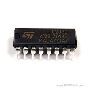
The L293 is a quadruple high-current half-H driver designed to provide bidirectional drive currents of up to 1A at voltages from 4.5V to 36V. It is ideal for driving inductive loads such as relays, solenoids, DC and stepping motors. The L293 IC is commonly used in robotics and embedded systems for motor control applications.
Key Features:
- Capable of driving two DC motors or one stepper motor
- Provides bidirectional drive currents up to 1A per channel
- Wide supply voltage range from 4.5V to 36V
- Separate input-logic supply
- Thermal shutdown protection
- High noise immunity
- Internal ESD protection
- Compatible with TTL and CMOS logic levels
Technical Specifications:
- Supply Voltage (VCC1 – Logic): 4.5V to 7V
- Supply Voltage (VCC2 – Motor): 4.5V to 36V
- Output Current: 1A per channel (continuous)
- Peak Output Current: 2A per channel (non-repetitive, t < 5ms)
- Input Voltage High: 2.3V (min)
- Input Voltage Low: 1.5V (max)
- Enable Voltage High: 2.3V (min)
- Enable Voltage Low: 1.5V (max)
- Power Dissipation: 5W (typical)
- Operating Temperature Range: 0°C to +70°C
- Package Type: 16-pin DIP (Dual In-line Package), SOIC (Small Outline Integrated Circuit), or TSSOP (Thin Shrink Small Outline Package)
Applications:
- Robotics
- Motor control for DC motors and stepper motors
- Relay drivers
- Solenoid drivers
- High current LED drivers
- Automotive applications
Usage:
- Connection:
- Connect VCC1 to the logic voltage (4.5V to 7V).
- Connect VCC2 to the motor voltage (4.5V to 36V).
- Connect the input pins (IN1, IN2, IN3, IN4) to the microcontroller or control logic.
- Connect the output pins (OUT1, OUT2, OUT3, OUT4) to the motor terminals.
- Enable the channels by connecting the enable pins (EN1, EN2) to the logic high or via PWM signals for speed control.
- Control:
- Use the input pins to set the direction of the motor rotation.
- Use PWM on the enable pins to control the speed of the motors.
- Protection:
- Ensure proper heat sinking or cooling as the IC can get hot under high loads.
- Use external diodes if necessary to protect against back EMF generated by motors.
Caution:
- Ensure the total current does not exceed the maximum ratings of the IC.
- Provide adequate cooling to prevent thermal shutdown.
- Avoid short circuits and excessive voltage spikes.
Datasheet:
For detailed technical specifications, refer to the L293 Motor Driver IC Datasheet.
|
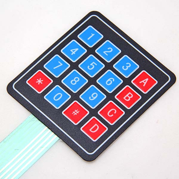
The 4×4 Matrix Keypad is a user-friendly input device consisting of 16 keys arranged in a 4×4 matrix. It is widely used in embedded systems, microcontroller projects, and DIY electronics for user input. Each key press is detected by scanning the matrix, allowing for efficient and reliable data entry. The keypad is compact, durable, and easy to integrate into various projects.
Key Features:
- Key Configuration: 4 rows and 4 columns, totaling 16 keys
- Interface: Matrix scanning
- Key Labels: Numeric and function keys (0-9, A-D, *, #)
- Compact Design: Suitable for handheld devices and small projects
- Durable: Made from high-quality materials for long-lasting use
- Flexible: Can be connected to any microcontroller or development board
- Low Power Consumption: Efficient operation with minimal power usage
Technical Specifications:
- Number of Keys: 16 (4×4 matrix)
- Operating Voltage: 3.3V to 5V
- Current Consumption: < 10mA
- Contact Resistance: ≤ 200 ohms
- Insulation Resistance: ≥ 100M ohms (at 250V DC)
- Operating Temperature Range: -20°C to +60°C
- Keypad Dimensions: 69mm x 69mm x 1.8mm
- Connection Type: 8-pin header
Applications:
- Embedded Systems: User input for microcontroller-based projects.
- DIY Electronics: Ideal for hobbyists and makers creating custom projects.
- Access Control: Use in security systems for code entry.
- Consumer Electronics: Keypad input for appliances and gadgets.
- Educational Projects: Commonly used in educational kits and learning modules.
Usage:
- Wiring: Connect the 8-pin header to the microcontroller or development board, ensuring correct row and column connections.
- Programming: Use libraries (e.g., Keypad library for Arduino) to read key presses and handle input.
- Integration: Incorporate the keypad into your project for reliable user input.
- Testing: Verify the functionality by pressing keys and checking the output.
Caution:
- Proper Connection: Ensure the keypad is connected correctly to avoid malfunction.
- Voltage Levels: Operate within the specified voltage range to prevent damage.
Datasheet:
For detailed technical specifications, refer to the 4×4 Matrix Keypad Datasheet.
|
The Servo Splitter 30cm is a practical accessory designed to split a single servo signal into multiple outputs, allowing you to control multiple servos simultaneously from a single receiver channel. This splitter is particularly useful in RC models, robotics, and other applications requiring synchronized servo movements. With a length of 30cm, it provides flexibility and convenience in your wiring setup.
Key Features:
- Signal Splitting: Allows one servo signal to control multiple servos
- Flexible Length: 30cm cable for convenient and flexible connections
- High-Quality Connectors: Secure and reliable connections to servos and receiver
- Durable Construction: Made from robust materials for long-lasting performance
- Easy Integration: Compatible with standard servo connectors and receiver channels
Technical Specifications:
- Cable Length: 30cm
- Connectors: Standard 3-pin servo connectors (male to multiple female)
- Wire Gauge: Typically 22 AWG for reliable signal transmission
- Material: High-quality plastic and metal connectors with durable insulation
- Compatibility: Compatible with most RC servos and receivers
- Weight: Lightweight for easy integration into various setups
Applications:
- RC models (airplanes, cars, boats)
- Robotics projects
- Synchronized servo control in DIY electronics
- Educational and hobbyist projects
- Any application requiring multiple servos controlled from a single channel
Usage:
- Connect the male end of the servo splitter to the receiver channel.
- Connect the female ends to the servos you wish to control.
- Ensure all connections are secure and free from obstructions.
- Power on your system and test the servo movements for proper synchronization.
Caution:
- Verify the compatibility of the splitter with your servos and receiver before use.
- Handle the connectors with care to avoid bending or damaging the pins.
- Ensure the splitter does not interfere with other components in your setup.
- Avoid excessive bending or twisting of the cable to maintain its integrity.
|
The PICkit 3 is a powerful programmer and debugger for Microchip’s PIC and dsPIC microcontrollers, utilizing the MPLAB Integrated Development Environment (IDE). It connects to a PC via a full-speed USB interface and interfaces with the target microcontroller through a Microchip debug (RJ-11) connector. This connector supports in-circuit debugging and In-Circuit Serial Programming (ICSP), providing comprehensive development and debugging capabilities. The device includes a miniUSB cable for easy connection.
Key Features:
- Supports programming and debugging of PIC and dsPIC microcontrollers
- Compatible with MPLAB Integrated Development Environment (IDE)
- Full-speed USB interface for connection to PC
- Microchip debug (RJ-11) connector for target microcontroller
- Supports In-Circuit Serial Programming (ICSP) and real-time debugging
Technical Specifications:
- Supported Devices: PIC and dsPIC microcontrollers
- Interface: USB 2.0 (Full Speed)
- Connector Type: Microchip debug (RJ-11), compatible with MPLAB ICD 2/3 and MPLAB REAL ICE
- Programming Voltage: 2.0V to 5.5V
- Debugging Features: In-circuit debugging, ICSP
- Included Accessories: MiniUSB cable
- Software Compatibility: MPLAB X IDE
Applications:
- Embedded systems development
- Microcontroller programming and debugging
- Prototype development
- Educational projects
Usage:
- Connect the PICkit 3 to a PC using the included miniUSB cable.
- Attach the PICkit 3 to the target microcontroller using the Microchip debug (RJ-11) connector.
- Launch MPLAB X IDE or compatible software for programming and debugging.
- Utilize the features for in-circuit debugging and ICSP.
Caution:
- Ensure correct connections and programming voltage to avoid damage.
- Follow the manufacturer’s guidelines for setup and use.
- Avoid static-sensitive environments to prevent damage.
Datasheet:
For detailed technical specifications, refer to the PICkit 3 Datasheet.
|
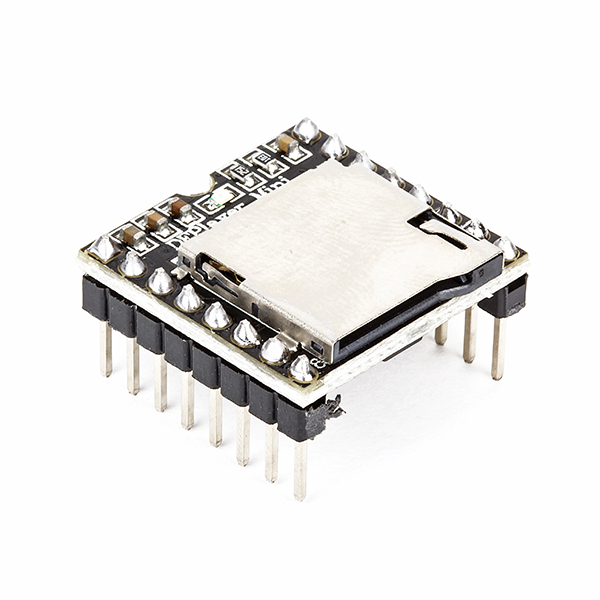
The DF Mini MP3 Player is a compact and cost-effective MP3 module that can be directly connected to a speaker. It can be used as a standalone module with battery, speaker, and push buttons, or in combination with an Arduino or other controller with RX/TX capabilities. It is widely used in applications like voice announcements, sound effects, and audio playback in various projects.
Key Features:
- Compact Size: Small form factor for easy integration
- Storage: Supports microSD cards up to 32GB
- File Format: MP3, WAV, and WMA file formats
- Built-in Amplifier: 3W amplifier for direct speaker connection
- Control Interface: Serial (UART), AD (Analog), or GPIO (General Purpose Input/Output)
- Power Supply: 3.2V to 5.0V DC
Technical Specifications:
- Operating Voltage: 3.2V to 5.0V DC
- Storage Medium: MicroSD card (up to 32GB)
- Audio Formats: MP3, WAV, WMA
- Amplifier: 3W built-in amplifier
- Control Interface:
- Serial (UART): For communication with microcontrollers
- AD (Analog): For controlling playback with potentiometers
- GPIO: For simple control using buttons or switches
- Output: Speaker (direct connection), headphone jack (if available)
- Dimensions: Compact and suitable for integration into various projects
Applications:
- Voice Announcements: Ideal for applications requiring voice prompts or messages.
- Sound Effects: Used in interactive displays, exhibits, and installations.
- Audio Playback: Suitable for DIY projects, toys, and educational tools.
- Embedded Systems: Integrated into products requiring audio feedback or instructions.
- Prototyping: Useful in developing and testing audio-based applications.
Datasheet:
For detailed technical information, refer to the DF Mini MP3 Player datasheet.
|
