Subtotal: ₦6,445.00
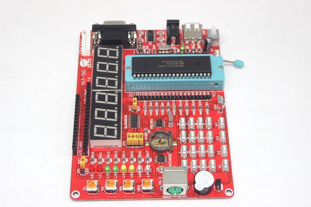
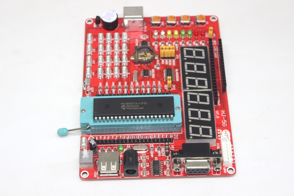
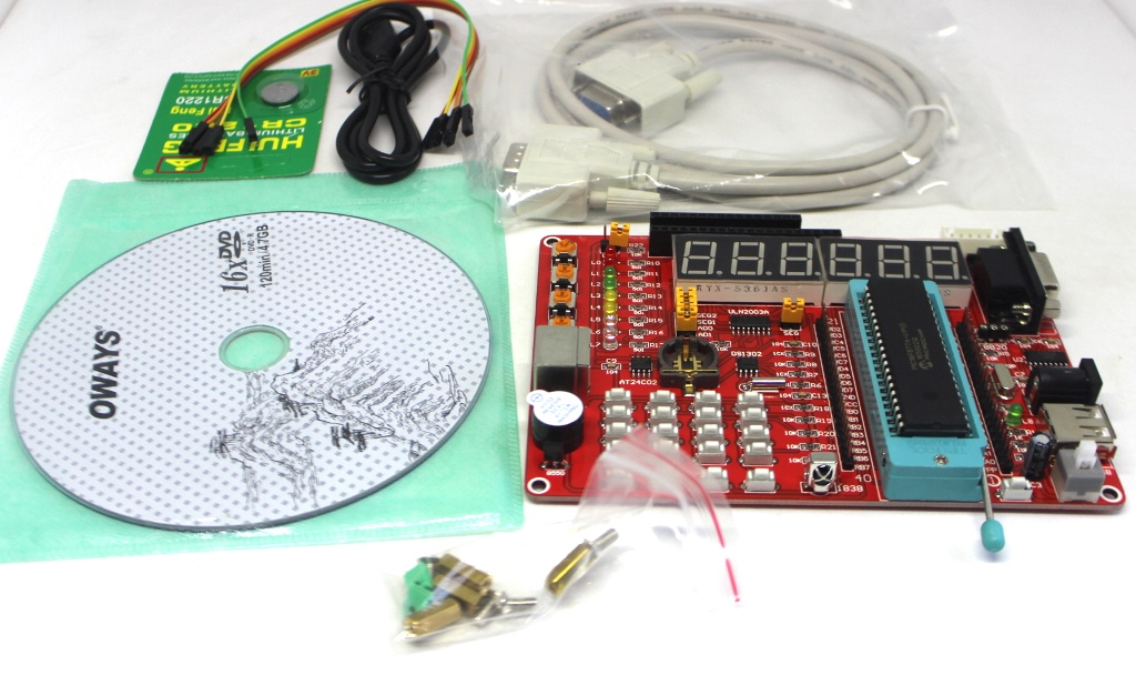
PIC 16F877A development board
₦36,200.00
Description:
The PIC 16F877A Development Board is a versatile platform designed for prototyping and developing applications based on the PIC16F877A microcontroller. This development board provides an integrated environment for programming, testing, and interfacing with peripherals, making it ideal for educational purposes, hobbyist projects, and professional development.
Key Features:
- Based on the PIC16F877A microcontroller
- Onboard crystal oscillator for clock generation
- Reset circuitry with push-button reset
- Power supply options (typically via USB or external power adapter)
- Headers and connectors for easy access to I/O pins and peripherals
- Onboard LEDs for visual feedback
- UART, SPI, I2C interfaces for communication
- Expansion headers for adding additional modules and sensors
Technical Specifications:
- Microcontroller: PIC16F877A
- Clock Frequency: Typically 20 MHz (crystal oscillator)
- Power Supply: Typically 5V DC
- Communication Interfaces: UART, SPI, I2C
- Onboard Components: LEDs, push buttons, reset circuit
- Expansion Headers: GPIO, analog inputs, PWM outputs
- Dimensions: Varies by board design
- Weight: Lightweight for portability
Applications:
- Educational projects and labs
- Embedded system prototyping
- Sensor interfacing and data acquisition
- IoT (Internet of Things) applications
- Automation and control systems
Datasheet:
For detailed technical information, refer to the PIC 16F877A microcontroller datasheet
In stock
The PIC16F877A Development Board can be used to evaluate and demonstrate the capabilities of Microchip PIC16F877A microcontroller. The MCU socket on board provides support for 40 pin DIP package of PIC16F877A controller. The board is designed for general purpose applications and includes a variety of hardware to exercise microcontroller peripherals. It is a fantastic tool for code debugging, development and prototyping. The all new board design have made it much more user-friendly than its predecessors, ideally suitable for training and development purposes. The components used in this board are of high quality and the PCB is high quality two layer PTH PCB, which makes this board especially durable. When you start using the eCee PIC16F877A Development Board you will find it to be one of the best development tool available for PIC16F877A controller. Here below you will find the key features of this product.
PIC 16F877A development board Features
- Compact and Ready to use design
- Professional EMI/RFI Complaint PCB Layout Design for Noise Reduction
- High Quality Two layer PTH PCB
- Includes PIC16F877A Microcontroller
- Board Supports PIC 18F4580/4520/4550* Microcontrollers
- No separate programmer required (Built in Boot loader)
- No Separate power adapter required (USB power source)
- Screw terminal for External power Supply (with Jumper Select Option)
- External Power Supply range of 7V to 20V
- Adaptor (any standard 9-12V power supply) option
- RS-232 Interface (For direct connection to PC’s serial port)
- On board Two Line LCD Display (2×16)
- On board I2C EEPROM (4K-AT24C04)
- On board I2C RTC (DS 1307) with Crystal and Battery
- Four multiplexed 7-Segment LED Display
- Built in Matrix keyboard (12 keys)
- Built in Pull-Up (4 Keys) Keyboard
- Built in IR Sensor Interface – TSOP 1738
- Built in 8 LED Interface to test I/O
- On Board External Interrupt and Reset buttons
- Built in Pot interface to ADC
- On Board Temperature Sensor Interface (LM35)
- On Board Buzzer Interface
- On Board PWM Output pin
- On Board ICD Connector for Debugging/Programming
- On Board ICSP Connector
- On Board 20 MHz Crystal Oscillator
- On Board Power LED Indicator
- All Port Pins available at IDC (2×5) Connector
- Can be used as main board for developing applications
- Power Supply Reverse Polarity Protection
- On Board 1 Amp Voltage Regulator
- Demo HEX codes included for testing of board features
- Example codes included
PIC16F877A Chip Specification
- Microchip PIC 16F877A (with 20 MHz Crystal Oscillator & Boot loader Software)
- High Performance RISC CPU
- 8 K Words Programmable Flash Memory
- 368 bytes Data Memory (RAM)
- 256 bytes EEPROM
- 20 MHz Operation (200ns instruction cycle)
- 33 I/O pins
- 8-Channel 10-bit Analog to Digital Converter (ADC)
- Two PWM Channels
- Two Capture modules (16-bit with max. resolution 12.5 ns)
- Two Compare modules (16-bit with max. resolution 200 ns)
- Two 8-Bit Timer/Counter
- One 16-Bit Timer/Counter
- One Serial USART
- One Master Synchronous Serial Port (MSSP)
- One Serial Peripheral Interface(SPI) Module
- One Inter-Integrated Circuit (I2C) Module
- Power-On Reset (POR), Power-Up Timer (PWRT) and Oscillator Start-up Timer (OST)
- Interrupt Capability (up to 14 sources)
- Eight Level Deep Hardware Stack
- ICSP Programming
- Brown Out Reset
- Low Voltage Programming
- Power Saving Sleep Mode
- Programmable Code Protection
- Fully Static Design
- Wide Operating Voltage 2.0V to 5.5V
- Low Power Consumption

