- You have no items in your shopping cart
- Subtotal: ₦0.00
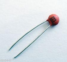
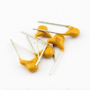
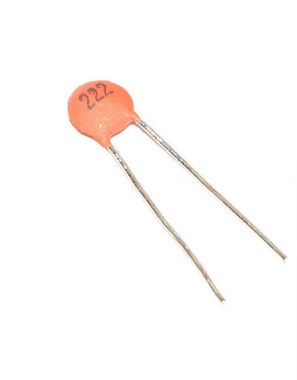
223 0.022uf 22nf 22000pf capacitor
₦45.00
The 223 0.022µF capacitor is a ceramic capacitor with a capacitance of 22 nanofarads (nF) or 0.022 microfarads (µF), equivalent to 22,000 picofarads (pF). Ceramic capacitors are widely used in electronic circuits for their stability, reliability, and low cost.
Key Features:
- Capacitance: 0.022µF (22nF, 22000pF)
- Type: Ceramic capacitor
- Voltage Rating: Commonly ranges from 50V to 100V or higher, depending on the application
- Temperature Stability: Stable over a wide temperature range
- Low equivalent series resistance (ESR)
Technical Specifications:
- Capacitance: 0.022µF (22nF, 22000pF)
- Voltage Rating: Typically 50V, 100V, or higher (check specific component marking)
- Tolerance: ±10% or ±20% (varies by manufacturer)
- Temperature Coefficient: Typically NP0 (C0G) for high stability, or X7R for general-purpose use
- Operating Temperature Range: -55°C to +125°C (varies by type)
- Body Size: Depends on the voltage rating and tolerance (e.g., 0805, 1206, etc. for surface mount)
- Type: Available in through-hole or surface mount packages
Applications:
- Decoupling and Bypassing: Used to filter out noise in power supply lines.
- Timing Circuits: Used in conjunction with resistors to create RC timing circuits.
- Signal Coupling and Decoupling: Facilitates AC signal transmission between circuit stages.
- Filtering: Used in filter circuits for audio and RF applications.
- Oscillators: Used in oscillator circuits for frequency determination.
Usage:
- Identify the Correct Capacitance Value: Ensure that 0.022µF is the required capacitance for your circuit.
- Check the Voltage Rating: Verify that the voltage rating meets or exceeds the circuit requirements.
- Position on PCB: Place the capacitor in the appropriate location on the printed circuit board (PCB).
- Soldering: Solder the capacitor leads (for through-hole) or pads (for surface mount) to the PCB, ensuring good mechanical and electrical connections.
- Verification: Test the circuit to ensure proper functionality and that the capacitor is operating within its specified limits.
Caution:
- Voltage Rating: Do not exceed the rated voltage to avoid capacitor failure.
- Polarity: While ceramic capacitors are generally non-polarized, ensure correct orientation if using polarized types.
- Handling: Handle with care to avoid mechanical damage to the capacitor body and leads.The 223 0.022µF capacitor is a ceramic capacitor with a capacitance of 22 nanofarads (nF) or 0.022 microfarads (µF), equivalent to 22,000 picofarads (pF). Ceramic capacitors are widely used in electronic circuits for their stability, reliability, and low cost.
Key Features:
- Capacitance: 0.022µF (22nF, 22000pF)
- Type: Ceramic capacitor
- Voltage Rating: Commonly ranges from 50V to 100V or higher, depending on the application
- Temperature Stability: Stable over a wide temperature range
- Low equivalent series resistance (ESR)
Technical Specifications:
- Capacitance: 0.022µF (22nF, 22000pF)
- Voltage Rating: Typically 50V, 100V, or higher (check specific component marking)
- Tolerance: ±10% or ±20% (varies by manufacturer)
- Temperature Coefficient: Typically NP0 (C0G) for high stability, or X7R for general-purpose use
- Operating Temperature Range: -55°C to +125°C (varies by type)
- Body Size: Depends on the voltage rating and tolerance (e.g., 0805, 1206, etc. for surface mount)
- Type: Available in through-hole or surface mount packages
Applications:
- Decoupling and Bypassing: Used to filter out noise in power supply lines.
- Timing Circuits: Used in conjunction with resistors to create RC timing circuits.
- Signal Coupling and Decoupling: Facilitates AC signal transmission between circuit stages.
- Filtering: Used in filter circuits for audio and RF applications.
- Oscillators: Used in oscillator circuits for frequency determination.
Usage:
- Identify the Correct Capacitance Value: Ensure that 0.022µF is the required capacitance for your circuit.
- Check the Voltage Rating: Verify that the voltage rating meets or exceeds the circuit requirements.
- Position on PCB: Place the capacitor in the appropriate location on the printed circuit board (PCB).
- Soldering: Solder the capacitor leads (for through-hole) or pads (for surface mount) to the PCB, ensuring good mechanical and electrical connections.
- Verification: Test the circuit to ensure proper functionality and that the capacitor is operating within its specified limits.
Caution:
- Voltage Rating: Do not exceed the rated voltage to avoid capacitor failure.
- Polarity: While ceramic capacitors are generally non-polarized, ensure correct orientation if using polarized types.
- Handling: Handle with care to avoid mechanical damage to the capacitor body and leads.
In stock
Be the first to review “223 0.022uf 22nf 22000pf capacitor”
You must be <a href="http://hub360.com.ng/my-account-3/">logged in</a> to post a review.




Reviews
There are no reviews yet.