|
Description |
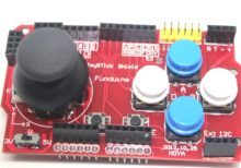
The Joystick Shield V1 is an expansion board designed for Arduino and other compatible microcontroller platforms. It features a joystick, buttons, and connectors that enable easy interfacing for a variety of applications, including gaming, robotics, and interactive projects. The shield provides an intuitive and user-friendly interface for controlling movements and actions in your projects.
Key Features:
- Analog Joystick: Two-axis joystick for precise control of movement.
- Push Buttons: Includes multiple push buttons for additional input options.
- Shield Design: Easily stackable on top of Arduino boards, maintaining a compact form factor.
- Plug and Play: Simple to connect and start using with minimal setup required.
- Versatile Applications: Suitable for gaming controllers, robotic controls, and interactive systems.
Technical Specifications:
- Joystick: 2-axis (X and Y) analog joystick with a push-button function
- Buttons: 5 push buttons (up, down, left, right, select)
- Interface: Connects to Arduino through the standard shield interface
- Operating Voltage: 5V (supplied by the Arduino board)
- Dimensions: Compatible with standard Arduino board dimensions
Applications:
- Gaming Controllers: Create custom gaming controllers for various platforms.
- Robotics: Use the joystick and buttons to control robotic movements and actions.
- Interactive Projects: Develop interactive installations and projects that require user input.
- Prototyping: Ideal for quickly testing and prototyping control interfaces.
Datasheet:
For detailed technical specifications, refer to the Joystick Shield V1 Datasheet.
|
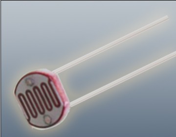
The Photoresistor LDR (Light Dependent Resistor) is a variable resistor whose resistance changes with the light intensity that falls upon it. It is widely used in light sensing applications and projects where detecting light levels is essential. LDRs are cost-effective, easy to use, and suitable for various electronic projects, including light meters, street lights, and other light-sensitive devices.
Key Features:
- Light Sensitivity: Resistance decreases with increasing light intensity
- Simple Interface: Easy to integrate with microcontrollers and analog circuits
- Low Cost: Economical solution for light detection
- Wide Range of Light Detection: Can detect various light levels from low to high intensity
- Compact Size: Fits easily into small projects
Technical Specifications:
- Resistance in Darkness: Typically 1MΩ (depending on specific model)
- Resistance in Bright Light: Typically 10-20kΩ (depending on specific model)
- Spectral Peak: Approximately 540nm (most sensitive to green light)
- Response Time: Rise time ~20ms, fall time ~30ms
- Operating Temperature Range: -30°C to +70°C
- Diameter: Typically 5mm to 10mm (depending on specific model)
Applications:
- Light Meters: Measure light intensity for photography and scientific applications.
- Street Lights: Automatic on/off control based on ambient light levels.
- Alarm Systems: Detect changes in light levels for security purposes.
- Consumer Electronics: Light-sensitive control in devices like clocks and displays.
- Educational Projects: Common component in learning modules for electronics.
Usage:
- Circuit Integration: Connect the LDR in a voltage divider circuit with a fixed resistor to create a variable voltage output based on light intensity.
- Microcontroller Interface: Read the voltage output from the LDR circuit using an analog input pin on a microcontroller.
- Programming: Write code to interpret the analog signal and perform actions based on light levels (e.g., turning on an LED when it gets dark).
- Testing: Calibrate the LDR circuit for the desired light sensitivity by adjusting the fixed resistor value.
Caution:
- Environment: Avoid exposure to extreme temperatures and humidity, which may affect the LDR’s performance.
- Handling: Handle with care to avoid damaging the sensitive surface of the LDR.
Datasheet:
For detailed technical specifications, refer to the Photoresistor LDR Datasheet.
|
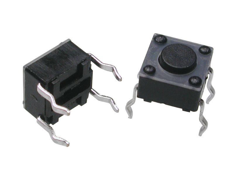
A Tact Switch, also known as a tactile switch, is a type of switch designed to provide a tactile feedback when pressed. These switches are commonly used in electronic devices for user input, such as in keyboards, remote controls, and various consumer electronics. Tact switches are known for their compact size, reliability, and ease of integration into circuits.
Key Features:
- Tactile Feedback: Provides a satisfying click feel when pressed.
- Compact Size: Small and suitable for space-constrained applications.
- Reliability: Durable and designed for a high number of actuation cycles.
- Variety of Sizes: Available in different sizes and heights to fit various designs.
- Easy Mounting: Can be mounted on PCBs with through-hole or surface-mount technology.
- Wide Application Range: Suitable for a variety of electronic devices and applications.
Technical Specifications:
- Contact Rating: Typically 50mA, 12V DC
- Contact Resistance: ≤ 100mΩ
- Insulation Resistance: ≥ 100MΩ at 100V DC
- Dielectric Strength: 250V AC for 1 minute
- Operating Force: Typically 160gf (varies by model)
- Travel: Typically 0.25mm to 0.5mm
- Operating Life: Typically 100,000 to 1,000,000 cycles
- Operating Temperature Range: -20°C to +70°C
Applications:
- Consumer Electronics: Used in remote controls, calculators, and gaming controllers.
- Computer Peripherals: Keyboards, mice, and other input devices.
- Home Appliances: Control panels for microwaves, washing machines, and other appliances.
- Automotive: Control buttons on car dashboards and steering wheels.
- Industrial Equipment: Control panels and user interfaces for machinery.
- DIY Projects: Suitable for custom electronic projects and prototypes.
Usage:
- Mounting: Solder the tact switch onto a PCB, ensuring correct alignment of the pins.
- Wiring: Connect the switch to your circuit, typically using pull-up or pull-down resistors.
- Testing: Verify the switch functionality by pressing it and checking the response in your circuit.
- Integration: Integrate the switch into your final product, ensuring it is accessible and functions as intended.
Caution:
- Debouncing: Implement debouncing in your software to ensure accurate readings.
- Proper Soldering: Avoid excessive heat during soldering to prevent damage to the switch.
- Environmental Conditions: Ensure the switch is used within its specified temperature and humidity range.
Datasheet:
For detailed technical specifications, refer to the Tact Switch Datasheet.
|


