|
Description |
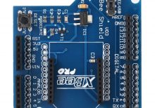
The Arduino XBee Expansion Board V3.0 is designed to facilitate easy integration of XBee modules with Arduino boards, providing a convenient platform for wireless communication projects. It allows XBee modules (such as XBee 802.15.4, Zigbee, or others) to be easily plugged into Arduino boards, enabling wireless communication capabilities without the need for extensive wiring.
Key Features:
- Compatibility: Compatible with Arduino Uno, Mega, and other compatible boards.
- XBee Socket: Provides a socket for XBee modules, supporting various XBee module types.
- Onboard Components: Includes necessary components for XBee module operation.
- Power Options: Supports both 3.3V and 5V operation, selectable via jumpers.
- Reset Button: Onboard reset button for resetting connected Arduino and XBee modules.
- Interface: Provides UART interface for communication between Arduino and XBee modules.
- Indicator LEDs: LEDs for power and status indication.
- Expansion Headers: Additional headers for connecting to Arduino I/O pins.
Applications:
- Wireless sensor networks
- Remote monitoring and control systems
- IoT (Internet of Things) projects
- Home automation systems
- Robotics and automation projects
Technical Specifications:
- Dimensions: Standard Arduino shield dimensions
- Power Supply: 5V DC input via Arduino board or external power source
- Communication: UART interface between Arduino and XBee module
- Operating Temperature: Typically -40°C to +85°C
Datasheet: For detailed technical information, refer to the Arduino XBee Expansion Board V3.0 datasheet.
|
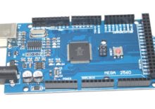
The MEGA2560 R3 CH340 is a microcontroller development board based on the ATmega2560, featuring a CH340 USB-to-serial converter. It is designed to provide a robust platform for various electronics projects, offering numerous digital and analog input/output pins, multiple communication interfaces, and compatibility with the Arduino IDE. The MEGA2560 R3 is ideal for projects requiring substantial memory and processing power.
Key Features:
- Microcontroller: ATmega2560
- USB-to-Serial Converter: CH340
- Digital I/O Pins: 54 (of which 15 provide PWM output)
- Analog Input Pins: 16
- Flash Memory: 256 KB (8 KB used by bootloader)
- SRAM: 8 KB
- EEPROM: 4 KB
- Clock Speed: 16 MHz
- Operating Voltage: 5V
- Input Voltage (recommended): 7-12V
- Input Voltage (limit): 6-20V
Technical Specifications:
- Microcontroller: ATmega2560
- USB-to-Serial Converter: CH340
- Operating Voltage: 5V
- Input Voltage (recommended): 7-12V
- Input Voltage (limits): 6-20V
- Digital I/O Pins: 54 (15 PWM)
- Analog Input Pins: 16
- DC Current per I/O Pin: 20 mA
- DC Current for 3.3V Pin: 50 mA
- Flash Memory: 256 KB (ATmega2560) of which 8 KB used by bootloader
- SRAM: 8 KB (ATmega2560)
- EEPROM: 4 KB (ATmega2560)
- Clock Speed: 16 MHz
Applications:
- Robotics: Ideal for controlling complex robotic systems.
- IoT Projects: Suitable for Internet of Things (IoT) applications with multiple sensors and actuators.
- Prototyping: Excellent for prototyping large-scale electronic systems.
- Automation: Used in home and industrial automation projects.
- Educational: Perfect for teaching advanced microcontroller programming and electronics.
Datasheet:
For detailed technical specifications, refer to the MEGA2560 R3 CH340 Datasheet.
|
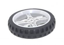
The 65mm Smart Car Tyre Narrow Wheel is designed for use in small robotics and smart car projects. These wheels provide excellent traction and durability, making them ideal for navigating various surfaces. Their narrow design allows for precise control and maneuverability, which is essential for robotics applications.
Key Features:
- Size: 65mm diameter, narrow width for precise control
- Durable Material: Made from high-quality rubber for enhanced durability and grip
- Easy Installation: Compatible with standard smart car and robot axles
- Smooth Performance: Ensures stable and smooth movement on various surfaces
- Lightweight: Lightweight construction for efficient energy use in small robotic projects
Technical Specifications:
- Diameter: 65mm
- Width: 8mm
- Material: High-quality rubber with plastic hub
- Axle Hole Diameter: 3mm
- Weight: 15g per wheel
- Color: Black
Applications:
- Smart Car Projects: Ideal for DIY smart car kits and educational robotics
- Robotics Competitions: Suitable for robotics competitions requiring precise control
- Line Following Robots: Enhances the performance of line-following robots
- Obstacle Avoidance Robots: Provides reliable movement for obstacle avoidance tasks
- Prototyping: Useful in various prototyping and small-scale robotics projects
|
NetPremise® is a data traffic extender that utilizes the existing electrical wiring/cables in a building (homes, hotels, offices, etc) to transmit data at high speeds of no less than **0Mbps (Megabits Per Second) up to distance of **0meters, and emits lossless data signals wirelessly or via Ethernet Ports located on the device.
Why NetPremise?
- Cost Reduction & Time Savings: Because NetPremise is a Powerline Communication Device (i.e. it utilizes already existing electrical wiring in a building), capital investment in procurement and installation of network and structural data cables is not required, thereby saving at least *0% of the time and effort required to install additional network infrastructure.
- Affordable: NetPremise is cheaper than all other network routers and extenders which essentially do not offer NetPremise’s intrinsic value.
- Lossless Data Transmission: Unlike other Wi-Fi range extenders, NetPremise’s signal cannot be disrupted by walls and other obstructions.
- Awards & Recognition: NetPremise® won the award for Best Innovative IT Product in November ***6 at the Nigeria Innovation Summit.
- Quality: Purchase of NetPremise comes with a one (1) year warranty.
- User Friendliness: NetPremise is a plug and play device, no rewiring or PVC trunking is required.
- Support: We are an indigenous Nigerian company inspired by our commitment to add immense value to our clients; NetPremise is proprietary and as such we offer onsite and remote support, with the capability to resolve all technical and non-technical challenges with the product.
|
The Photoelectric Metal Sensor LJ12A34 is an industrial-grade proximity sensor designed to detect metal objects within a specified range. This sensor uses photoelectric technology to detect the presence of metallic items without making physical contact, making it ideal for applications where non-contact detection is essential. It is widely used in automation, manufacturing, robotics, and various industrial applications.
Key Features:
- Detection Method: Photoelectric proximity detection
- Sensing Distance: Up to 4mm for metallic objects
- Output Type: NPN normally open (NO)
- Operating Voltage: 6-36V DC
- Response Time: Fast response time for real-time detection
- Indicator: Built-in LED indicator for detection status
- Durability: Robust construction for industrial environments
- Installation: Easy mounting with threaded barrel design
Technical Specifications:
- Dimensions:
- Sensor Diameter: 12 mm
- Length: 60 mm
- Weight: Approximately 30 g
- Sensing Distance: 4 mm (for iron)
- Output Current: 300 mA max
- Operating Temperature: -25°C to +70°C
- Humidity: 35% to 95% RH
- Response Frequency: 1 kHz
- Material: Metal housing with plastic sensing face
- Cable Length: 1.2 meters
Applications:
- Automation: Used in automated systems to detect the presence of metal parts.
- Manufacturing: Ideal for production lines to ensure the correct placement of metal components.
- Robotics: Used in robots for object detection and avoidance.
- Safety Systems: Integrated into safety systems to detect the presence or absence of metal objects.
- Quality Control: Helps in quality control processes by detecting metal parts during manufacturing.
Datasheet:
For detailed technical information, refer to the Photoelectric Metal Sensor LJ12A34 Datasheet.
|
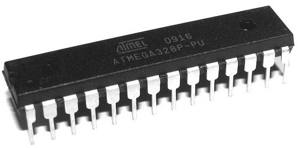
The Atmega 328P-PU is a high-performance, low-power 8-bit AVR microcontroller from Microchip Technology, commonly used in Arduino boards like the Arduino Uno. It features advanced RISC architecture with 32KB of ISP flash memory, 2KB of SRAM, and 1KB of EEPROM. This microcontroller is suitable for a wide range of applications, including embedded systems, consumer electronics, and DIY electronics projects.
Key Features:
- Advanced RISC architecture
- 32KB of in-system self-programmable flash memory
- 2KB SRAM and 1KB EEPROM
- 23 general-purpose I/O lines
- 32 general-purpose working registers
- Three flexible timer/counters with compare modes
- Internal and external interrupts
- Serial programmable USART
- Master/slave SPI serial interface
- On-chip analog comparator
- 10-bit ADC with 6 multiplexed channels
- Operating voltage range of 1.8V to 5.5V
- Low power consumption in active and sleep modes
Technical Specifications:
- Architecture: 8-bit AVR
- Flash Memory: 32KB
- SRAM: 2KB
- EEPROM: 1KB
- Clock Speed: Up to 20 MHz (with external crystal)
- Operating Voltage: 1.8V to 5.5V
- Digital I/O Pins: 23
- PWM Channels: 6
- Analog Input Channels: 6
- ADC Resolution: 10-bit
- Timers: 1 x 16-bit, 2 x 8-bit
- Communication Interfaces: USART, SPI, I2C
- Package Type: PDIP-28 (Plastic Dual In-line Package)
- Operating Temperature Range: -40°C to +85°C
Applications:
- Arduino development boards
- Consumer electronics
- Embedded systems
- Robotics
- Home automation
- DIY electronics projects
- Industrial automation
Usage:
- Programming:
- Use an AVR programmer or Arduino board to program the Atmega 328P-PU.
- Commonly programmed using the Arduino IDE for ease of use.
- Connect the microcontroller to your development environment using the appropriate hardware and software tools.
- Circuit Design:
- Integrate the Atmega 328P-PU into your circuit with necessary external components like crystal oscillators, capacitors, and resistors.
- Ensure proper power supply and grounding for stable operation.
- Interfacing:
- Utilize the I/O pins for interfacing with sensors, actuators, displays, and other peripherals.
- Use communication interfaces like USART, SPI, and I2C for data exchange with other devices.
Caution:
- Handle the microcontroller with care to avoid damage from electrostatic discharge (ESD).
- Ensure proper power supply voltage and connections to prevent damage.
- Follow the manufacturer’s guidelines for programming and operation.
Datasheet:
For detailed technical specifications, refer to the Atmega 328P Datasheet.
|
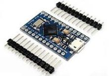
The Arduino Pro Micro is a compact and versatile microcontroller board based on the ATmega32U4 microchip. It is part of the Arduino family and designed for projects where space is limited. The Pro Micro board features built-in USB capabilities, allowing it to emulate a keyboard, mouse, or other USB devices, making it suitable for a wide range of applications including custom input devices and embedded systems.
Key Features:
- Microcontroller: ATmega32U4
- Operating Voltage: 5V
- Input Voltage (recommended): 7-12V
- Digital I/O Pins: 18
- Analog Input Pins: 9
- Flash Memory: 32 KB (ATmega32U4), of which 4 KB used by bootloader
- SRAM: 2.5 KB
- EEPROM: 1 KB
- Clock Speed: 16 MHz
- USB: Built-in USB functionality for direct connection to computers and emulation of USB devices
Technical Specifications:
- Dimensions: 33 mm x 18 mm
- Weight: Approximately 8 g
- Communication: UART, SPI, I2C, USB
- On-board LEDs: TX, RX, Power, and one user-defined LED
- Power:
- DC Current per I/O Pin: 40 mA
- DC Current for 3.3V Pin: 50 mA
- Connectors:
- USB Micro-B for programming and power
- 6-pin header for serial communication
- Pins for additional communication interfaces and power
Applications:
- Custom Input Devices: Can be used to create custom keyboards, mice, and other input devices.
- Embedded Systems: Suitable for small-scale embedded projects where USB connectivity is required.
- Prototyping: Ideal for rapid prototyping and development due to its compact size and USB capability.
- IoT Projects: Can be integrated into Internet of Things (IoT) devices for various control and monitoring applications.
- Wearables: Perfect for wearable electronics and projects requiring a small form factor.
Datasheet:
For detailed technical information, refer to the Arduino Pro Micro Datasheet.
|
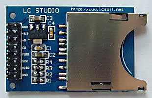
The SD Card Module is a compact and efficient solution for adding storage capabilities to your microcontroller or development board projects. It allows you to read from and write to SD cards, making it ideal for data logging, file storage, and other applications requiring large amounts of memory. The module supports various SD card formats and interfaces seamlessly with popular microcontrollers like Arduino, Raspberry Pi, and others.
Key Features:
- Storage: Supports SD, SDHC, and MicroSD (with adapter) cards
- Interface: SPI interface for easy integration
- Voltage Compatibility: Operates at 3.3V and 5V
- Onboard 3.3V Regulator: Ensures stable operation
- Card Detection: Built-in card detection switch
- Compact Design: Small footprint for easy incorporation into projects
- File System: Compatible with FAT16 and FAT32 file systems
Technical Specifications:
- Supported Cards: SD, SDHC, MicroSD (with adapter)
- Operating Voltage: 3.3V/5V
- Interface: SPI
- Current Consumption: < 100mA
- File System: FAT16, FAT32
- Dimensions: 42mm x 24mm x 12mm
Applications:
- Data Logging: Store sensor data and logs in embedded systems.
- File Storage: Save files for multimedia applications and projects.
- Firmware Updates: Load new firmware from the SD card for microcontrollers.
- DIY Projects: Perfect for hobbyists needing additional storage.
- Educational Projects: Commonly used in learning modules for data storage and retrieval.
Usage:
- Wiring: Connect the SD card module to your microcontroller using the SPI interface (CS, MOSI, MISO, SCK, VCC, GND).
- Power Supply: Ensure the module is powered with 3.3V or 5V, as required.
- Card Insertion: Insert a formatted SD card into the module.
- Programming: Use libraries (e.g., SD library for Arduino) to initialize the SD card and read/write data.
- Data Handling: Store or retrieve data files from the SD card as needed by your application.
Caution:
- Voltage Levels: Ensure proper voltage levels to avoid damaging the module.
- Handling SD Cards: Handle SD cards with care to prevent data loss or corruption.
Datasheet:
For detailed technical specifications, refer to the SD Card Module Datasheet.
|
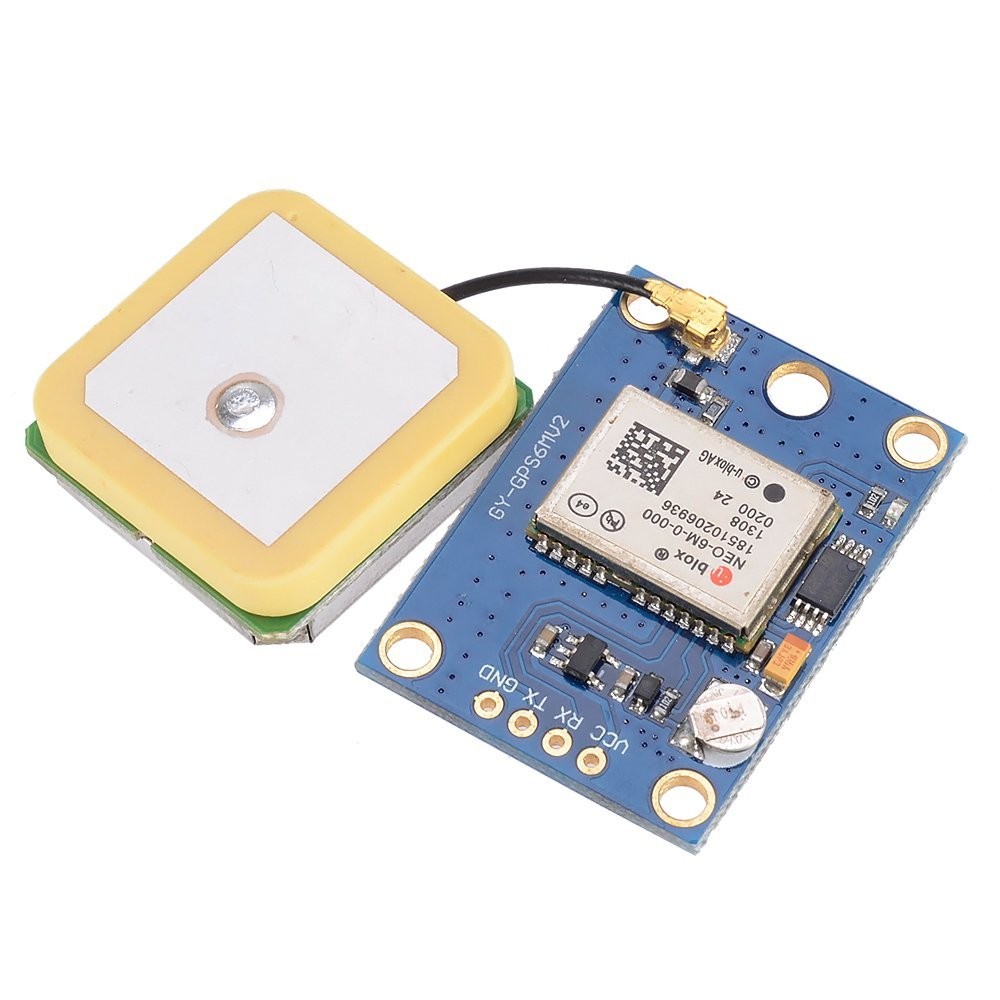
The NEO-6M V2 GPS Module is a highly reliable and precise GPS receiver designed for various applications requiring accurate location tracking and timing. This module is based on the u-blox NEO-6M GPS receiver, providing high sensitivity and low power consumption. It is widely used in navigation, tracking, and timing applications.
Key Features:
- High sensitivity and accuracy
- Supports GPS, QZSS, and SBAS (WAAS, EGNOS, MSAS)
- Low power consumption
- Compact size and easy integration
- Built-in EEPROM for configuration storage
- Onboard battery for faster cold starts
- TTL logic level compatible
- Antenna connection with SMA connector
Technical Specifications:
- Receiver Type: 50 channels, GPS L1 C/A code
- Sensitivity: -161 dBm (tracking), -148 dBm (cold starts)
- Update Rate: Up to 5 Hz
- Accuracy: Position: 2.5 m CEP, Velocity: 0.1 m/s, Time: 30 ns
- Cold Start Time: 27 seconds
- Hot Start Time: 1 second
- Operating Voltage: 3.3V to 5V
- Power Consumption: 37 mA
- Communication Interface: UART (TTL), default baud rate: 9600 bps
- Antenna: External active antenna via SMA connector
- Dimensions: 25 mm x 35 mm x 6 mm
- Operating Temperature Range: -40°C to +85°C
Applications:
- Vehicle and personal navigation
- Asset tracking
- Drone and UAV navigation
- Timing applications
- Geocaching
- Marine navigation
- Location-based services
Usage:
- Power Supply: Connect the module to a 3.3V or 5V power supply.
- Antenna Connection: Attach an external active GPS antenna to the SMA connector.
- Communication Setup: Connect the UART pins (TX, RX) to a microcontroller or serial interface with a compatible TTL logic level.
- Configuration: Configure the module settings if necessary using appropriate software or commands.
- Data Reception: Receive GPS data through the UART interface and process it for your application.
- Position Fix: Wait for the module to acquire satellite signals and provide a position fix.
Caution:
- Ensure the module is powered within the specified voltage range.
- Use a suitable GPS antenna for optimal performance.
- Follow proper ESD handling procedures to prevent damage.
- Place the antenna in a location with a clear view of the sky for best signal reception.
Datasheet:
For detailed technical specifications, refer to the NEO-6M V2 GPS Module Datasheet.
|
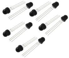
The LF0038 infrared receiver module is designed for receiving infrared signals from remote controls or other IR transmitters. It is commonly used in remote control systems, data communication, and various electronics projects that require IR signal detection. The module receives signals in the infrared spectrum and converts them into electrical signals that can be processed by a microcontroller or other digital logic.
Key Features:
- Type: Infrared Receiver Module
- Reception Range: Typically for standard remote control frequencies
- Output Type: Digital (high or low signal based on IR signal detection)
- Compatibility: Works with standard IR remote control protocols
Technical Specifications:
- Carrier Frequency: 38 kHz (common frequency for IR remote controls)
- Operating Voltage: 5V DC (common for microcontroller interfaces)
- Output Type: Digital Output (transmits high or low signals based on IR detection)
- Detection Range: Typically up to 5 meters, depending on the IR transmitter strength and environmental conditions
- Sensitivity: Designed to detect signals from standard IR remote controls
- Package Type: Usually a compact, surface-mount or through-hole package
Applications:
- Remote Control Systems: Receives signals from remote control devices for consumer electronics
- Data Communication: Used in IR communication systems for short-range data transfer
- Robotics: For implementing remote control functions in robotic systems
- Home Automation: Integrated into home automation systems for control via IR remote
Usage:
- Connection: Connect the VCC and GND pins of the LF0038 module to the power supply and ground of your circuit (typically 5V DC).
- Signal Output: Connect the output pin to a digital input pin of a microcontroller or logic circuit to read the IR signal.
- Programming: Write software or firmware to interpret the digital signals received from the module according to the IR protocol used by your remote control.
- Testing: Test the module with an IR remote control to ensure proper signal reception and decoding.
Caution:
- Power Supply: Ensure correct voltage is applied to avoid damage.
- Signal Range: Verify that the module’s range is suitable for your application; performance can vary with different IR transmitters.
- Ambient Interference: IR signals can be affected by ambient light and obstructions; ensure the line of sight between the transmitter and receiver is clear for reliable operation.
Datasheet:
For detailed technical specifications, pin configuration, and application examples, refer to the LF0038 Infrared Receiver Module Datasheet
|
Description:
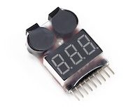
The 1-8S LiPo battery voltage detector with buzzer is an essential tool for monitoring and ensuring the safe operation of lithium polymer (LiPo) batteries used in RC models, drones, and other electronic devices. It provides real-time voltage detection for 1 to 8 series LiPo batteries, alerting users to low voltage conditions with an audible buzzer alarm. This compact device helps prevent over-discharge, which can damage batteries and reduce their lifespan, ensuring optimal performance and safety during use.
Key Features:
- Compatible Battery Types: 1-8S LiPo/Li-ion/LiMn/LiFe
- Voltage Detection Range: 2.7V to 25.2V (1S to 8S)
- Audible Buzzer Alarm: Alerts when voltage drops below preset levels
- Compact and Lightweight: Easy to carry and use in the field
- LED Indicators: Display battery voltage status for quick reference
- Reverse Polarity Protection: Prevents damage due to incorrect battery connection
Technical Specifications:
- Input Voltage: DC 5-27V (powered by the battery being tested)
- Accuracy: ±0.01V
- Operating Temperature: 0°C to 40°C
- Dimensions: Compact and portable design
- Weight: Lightweight for easy handling
Applications:
- RC Models (Cars, Planes, Boats)
- Drones and UAVs (Unmanned Aerial Vehicles)
- Portable Electronic Devices
- Battery Maintenance and Monitoring
|
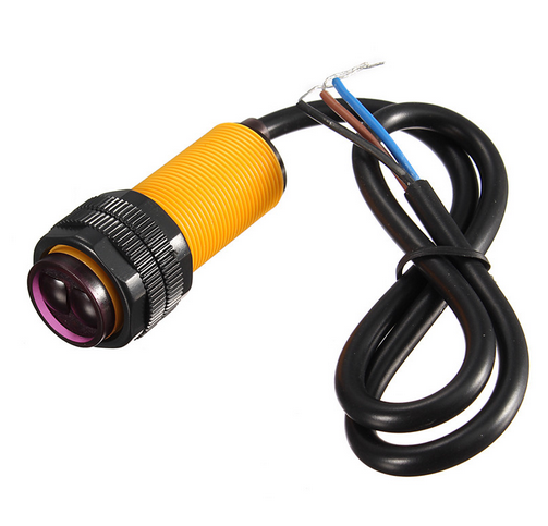
The Infrared Obstacle Sensor E18-D80 is a versatile sensor used for detecting obstacles and measuring distance through infrared light reflection. It operates by emitting an infrared beam and detecting the reflected signal from an object. The sensor is widely used in robotics, automation systems, and various applications where proximity detection is required.
Key Features:
- Detection Method: Infrared reflection
- Sensing Range: Adjustable from 3 cm to 80 cm
- Output Type: Digital (high or low signal) or Analog (varies by model)
- Operating Voltage: 5V DC
- Response Time: Fast response for real-time obstacle detection
- Indicator: LED indicator for operational status
- Adjustable Sensitivity: Allows for tuning the detection distance
Technical Specifications:
- Dimensions:
- Sensor Length: 40 mm
- Width: 30 mm
- Height: 25 mm
- Weight: Approximately 20 g
- Operating Voltage: 5V DC
- Detection Range: 3 cm to 80 cm
- Output Type:
- Digital: ON/OFF signal
- Analog: Varies by model
- Response Time: <100 ms
- Material: Plastic housing with infrared emitter and detector
- Cable Length: 15 cm (typically, varies by supplier)
Applications:
- Robotics: Used in robots for obstacle avoidance and distance measurement.
- Automation: Integrates into automated systems for object detection and collision prevention.
- Security Systems: Helps in motion detection and intrusion alarms.
- Consumer Electronics: Used in devices for proximity sensing and interactive applications.
- Industrial Applications: Detects the presence of objects on production lines or in machinery.
Datasheet:
For detailed technical information, refer to the Infrared Obstacle Sensor E18-D80 Datasheet.
|
A tilt sensor is a device used to detect the orientation or inclination of an object. It is typically used in various applications where it is necessary to detect changes in position or to determine if an object has tilted beyond a certain angle. Tilt sensors are widely used in robotics, automotive systems, security systems, and electronic devices for motion detection and orientation sensing.
Key Features:
- Detects changes in orientation or tilt
- Simple and reliable design
- Provides digital output signal
- Low power consumption
- Compact and easy to integrate
- Suitable for a wide range of applications
Technical Specifications:
- Type: Tilt Sensor
- Operating Voltage: Typically 3.3V to 5V (varies by model)
- Output Type: Digital (HIGH/LOW)
- Tilt Angle Range: Typically 15° to 45° (varies by model)
- Current Consumption: Typically less than 1mA
- Dimensions: Varies by product (commonly around 10mm x 5mm x 5mm)
- Operating Temperature Range: -40°C to +85°C
Applications:
- Robotics and automation
- Automotive safety systems
- Security and alarm systems
- Consumer electronics
- Motion detection and orientation sensing
- Industrial equipment
Usage:
- Connect the tilt sensor to your microcontroller or development board, ensuring proper connection of the power supply (VCC, GND) and the output pin.
- Use the digital output signal to detect tilt: the sensor typically outputs a HIGH signal when in the default position and a LOW signal when tilted beyond the specified angle.
- Implement code to monitor the sensor output and trigger appropriate actions or alarms when a tilt is detected.
- Mount the sensor on the object or surface where tilt detection is required, ensuring it is securely positioned.
Caution:
- Ensure proper orientation and mounting of the sensor for accurate tilt detection.
- Avoid exposing the sensor to excessive vibrations or shocks, which may affect its performance.
- Handle the sensor carefully to avoid damage to the internal components.
Datasheet:
For detailed technical specifications, refer to the specific product datasheet provided by the manufacturer.
|
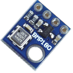
The BMP180 is a high-precision digital barometer and altitude sensor from Bosch, designed to measure atmospheric pressure and temperature. It is commonly used in applications requiring accurate altitude measurement and weather monitoring. The BMP180 provides reliable data for various applications including GPS, weather stations, and altitude tracking in wearable devices.
Key Features:
- Accurate barometric pressure and temperature measurement
- Digital interface with I²C or SPI communication
- High resolution with 0.03 hPa pressure measurement accuracy
- Compact and low-power design
- Built-in calibration for precise readings
- Wide operating temperature range
Technical Specifications:
- Sensor Type: Barometric Pressure and Temperature Sensor
- Communication Protocol: I²C (default), SPI (optional)
- Pressure Range: 300 hPa to 1100 hPa
- Pressure Accuracy: ±1 hPa (typical)
- Temperature Range: -40°C to +85°C
- Temperature Accuracy: ±1°C
- Resolution: 0.03 hPa for pressure
- Operating Voltage: 1.8V to 3.6V
- Current Consumption: 3µA (typical in sleep mode), 10µA (typical in measurement mode)
- Package Type: LGA-8 (Leadless Grid Array)
Applications:
- Altitude and weather tracking
- GPS altitude calibration
- Pressure-based data logging
- Environmental monitoring
- Wearable devices and consumer electronics
Usage:
- Connect the BMP180 sensor to your microcontroller or development board using I²C or SPI interface.
- Power the sensor with a voltage within the operating range (1.8V to 3.6V).
- Use the appropriate library or driver for the I²C or SPI protocol to interface with the sensor.
- Retrieve and process pressure and temperature data according to your application needs.
Caution:
- Ensure proper voltage supply to avoid damage to the sensor.
- Handle the sensor carefully to prevent mechanical damage or contamination.
- Verify correct wiring and communication protocol settings for accurate readings.
Datasheet:
For detailed technical specifications, refer to the BMP180 Datasheet.
|
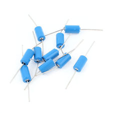
The Tilt Sensor (Blue) is a versatile sensor designed to detect the angle of inclination or tilt in various applications. It uses a mercury switch or a ball-and-cup mechanism to detect changes in orientation. This sensor is commonly used in electronics projects, robotics, and systems where tilt detection is crucial for proper functioning or safety.
Key Features:
- Detection Mechanism: Mercury switch or ball-and-cup mechanism
- Output Type: Digital (Normally open or closed switch)
- Operating Voltage: 3V to 12V DC
- Sensitivity: Detects tilt at various angles (typically ±45°)
- Response Time: Instantaneous response to tilt changes
- Indicator: Blue color for easy identification
- Durability: Reliable and robust for various applications
Technical Specifications:
- Dimensions:
- Sensor Diameter: 25 mm
- Height: 10 mm
- Weight: Approximately 10 g
- Operating Voltage: 3V to 12V DC
- Output Type: Digital (On/Off switch)
- Tilt Angle: ±45° (varies by model)
- Response Time: Immediate (depends on tilt angle)
- Material: Plastic housing with internal tilt mechanism
- Cable Length: 15 cm (typically, varies by supplier)
Applications:
- Robotics: Detects the tilt of a robot to trigger actions or adjust orientation.
- Safety Systems: Used in devices to detect accidental tilting or tipping.
- Consumer Electronics: Helps in features that adjust based on the device’s tilt.
- Automotive: Used in vehicles for tilt detection and stability control.
- Games and Toys: Provides tilt-sensitive controls in gaming or interactive toys.
Datasheet:
For detailed technical information, refer to the Tilt Sensor (Blue) Datasheet.
|
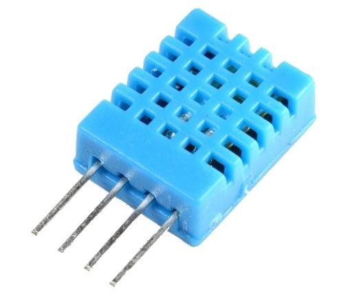
The DHT11 is a basic, ultra-low-cost digital temperature and humidity sensor. It uses a capacitive humidity sensor and a thermistor to measure the surrounding air and outputs a digital signal on the data pin. It’s simple to use but requires careful timing to grab data. It’s perfect for DIY projects, weather stations, and other applications where accurate and reliable temperature and humidity readings are needed.
Key Features:
- Temperature Range: 0-50°C with ±2°C accuracy
- Humidity Range: 20-80% RH with ±5% RH accuracy
- Low Power Consumption: Efficient for battery-operated applications
- Single Wire Digital Interface: Easy to interface with microcontrollers
- Pre-calibrated: No need for additional calibration
- Compact Size: Suitable for compact projects and devices
Technical Specifications:
- Temperature Range: 0-50°C (32-122°F)
- Humidity Range: 20-80% RH
- Temperature Accuracy: ±2°C
- Humidity Accuracy: ±5% RH
- Operating Voltage: 3.3V to 5.5V
- Max Current: 2.5mA
- Output: Digital signal via 1-wire protocol
- Dimensions: 15.5mm x 12mm x 5.5mm
Applications:
- Weather Stations: Monitor and log temperature and humidity levels.
- Home Automation: Control HVAC systems based on environmental conditions.
- Greenhouses: Maintain optimal growing conditions for plants.
- DIY Projects: Perfect for hobbyists building custom sensors and gadgets.
- Data Loggers: Record environmental data over time for analysis.
- Educational Projects: Teach students about sensors and data acquisition.
Usage:
- Wiring: Connect the VCC pin to 3.3V or 5V, GND to ground, and the DATA pin to a digital input on your microcontroller.
- Library Integration: Use libraries available for platforms like Arduino or Raspberry Pi to simplify reading data from the sensor.
- Coding: Write code to initialize the sensor and read temperature and humidity data.
- Data Processing: Process and use the sensor data in your application as needed, such as displaying it on an LCD or sending it to a web server.
Caution:
- Power Supply: Ensure the sensor is supplied with the correct voltage to avoid damage.
- Environmental Conditions: Keep the sensor in a dust-free, non-condensing environment for accurate readings.
- Wiring Length: Minimize the length of wiring between the sensor and the microcontroller to maintain signal integrity.
Datasheet:
For detailed technical specifications, refer to the DHT11 Datasheet.
|
