|
Description |
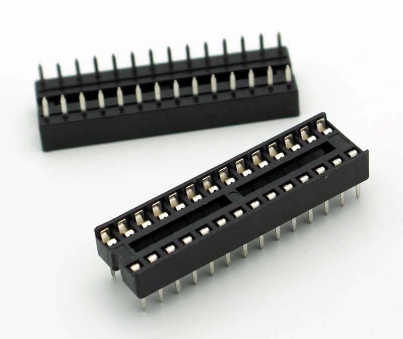
The IC Socket with 28 pins is a precision-molded, dual-in-line (DIP) socket designed to house integrated circuits (ICs) with 28 pins. It provides a reliable and convenient way to mount ICs on a printed circuit board (PCB) without soldering the IC directly, allowing for easy replacement and reusability. The socket ensures a secure and stable connection while protecting the IC from potential damage during assembly or troubleshooting.
Key Features:
- Accommodates ICs with 28 pins in a dual-in-line package (DIP)
- Facilitates easy insertion and removal of ICs
- Precision-molded body for reliable and stable connections
- Tin-plated or gold-plated contacts for excellent conductivity and corrosion resistance
- Low insertion force for easy handling
- Compatible with standard PCBs
- Available in various heights and profiles to suit different applications
Technical Specifications:
- Number of Pins: 28
- Pin Pitch: 2.54mm (0.1 inches)
- Contact Material: Tin-plated or gold-plated contacts
- Body Material: High-temperature thermoplastic
- Operating Temperature Range: -40°C to +105°C
- Dimensions: Varies by manufacturer (common size: 35mm x 10mm x 5mm)
- Mounting Type: Through-hole
Applications:
- Prototyping and development of electronic circuits
- Easy replacement and upgrading of ICs
- Protecting ICs from heat damage during soldering
- Ensuring reliable connections in electronic devices
- Use in educational and hobbyist projects
Usage:
- Insert the IC socket into the PCB aligning the pins with the corresponding holes.
- Solder the socket pins to the PCB, ensuring proper connection.
- Insert the IC into the socket, ensuring correct orientation.
- Press the IC gently but firmly to secure it in place.
Caution:
- Ensure correct orientation of the IC when inserting into the socket.
- Handle the IC and socket carefully to avoid bending or damaging the pins.
- Verify all connections before powering the circuit.
Datasheet:
For detailed technical specifications, refer to the IC Socket Datasheet.
|
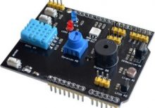
The 9 in 1 multifunctional expansion shield is designed to provide a versatile and convenient interface for microcontroller boards, such as Arduino. It integrates multiple functionalities into a single shield, allowing users to easily expand the capabilities of their microcontroller projects with minimal wiring and setup.
Key Features:
- Versatility: Combines multiple functions into one shield, reducing the need for additional components.
- Ease of Use: Simplifies the process of adding multiple functionalities to your project.
- Compatibility: Designed to be compatible with popular microcontroller platforms, such as Arduino.
Integrated Functions:
- Relay Module: Control high voltage devices with a relay switch.
- Button Inputs: Multiple push buttons for user input.
- LED Indicators: Multiple LEDs for status indication and visual feedback.
- Temperature Sensor: Integrated sensor for temperature measurement.
- Light Sensor: Detect ambient light levels.
- Buzzer: Sound output for alarms or notifications.
- Potentiometer: Adjustable resistance for analog input.
- I2C Interface: Connect additional I2C devices.
- UART Interface: Serial communication with other devices.
Technical Specifications:
- Relay Module: Typically supports up to 10A at 250V AC or 30V DC
- LED Indicators: Standard LEDs for status indication
- Temperature Sensor: Integrated temperature sensor (e.g., LM35 or similar)
- Light Sensor: Photodiode or similar light-detecting component
- Buzzer: Small piezoelectric buzzer for sound output
- Potentiometer: Adjustable knob for varying resistance
- I2C Interface: Standard I2C pins for connecting external devices
- UART Interface: TX/RX pins for serial communication
Applications:
- Prototyping: Ideal for rapid prototyping of microcontroller projects.
- Education: Useful for teaching and learning about microcontroller interfaces and sensors.
- DIY Projects: Great for hobbyists building custom electronics projects.
- Home Automation: Suitable for creating smart home devices with multiple inputs and outputs.
- Robotics: Useful in robotics projects requiring multiple sensors and actuators.
Datasheet:
For detailed technical information, refer to the 9 in 1 Multifunctional Expansion Shield datasheet provided by the manufacturer.
|
The PIC12F675 is an 8-bit microcontroller from Microchip’s PIC12 family, known for its low-power operation and compact size. It is designed for applications requiring a small form factor and includes integrated peripherals like timers and an Analog-to-Digital Converter (ADC), making it suitable for simple control tasks and sensor interfacing.
Key Features:
- 8-bit microcontroller with 14-bit instruction set architecture
- 128 bytes of RAM
- 256 bytes of EEPROM
- 10-bit Analog-to-Digital Converter (ADC)
- Two Timer modules (Timer0 and Timer1)
- Watchdog Timer (WDT)
- Capture/Compare/PWM (CCP) module
- Low-power operation with multiple sleep modes
- 6-bit wide I/O ports
- Internal oscillator
Technical Specifications:
- Operating Voltage: 2.0V to 5.5V
- Operating Frequency: Up to 20MHz
- Program Memory Size: 1KB (Flash)
- Data Memory Size: 64 bytes SRAM
- EEPROM Size: 128 bytes
- Number of I/O Pins: 6
- Timers: 8-bit Timer0, 8-bit Timer1
- ADC Resolution: 10-bit
- Package Type: 8-pin PDIP, 8-pin SOIC
Applications:
- Consumer electronics
- Battery-operated devices
- Simple sensor interfacing
- LED and display control
- Remote controls
- Low-power embedded systems
Usage:
- Connect the microcontroller to a power supply within the recommended voltage range.
- Program the PIC12F675 using its Flash program memory for specific tasks.
- Utilize the ADC for analog signal processing and Timer modules for timing tasks.
- Manage power consumption effectively using sleep modes for battery-operated applications.
Caution:
- Check power supply and connections to prevent damage.
- Handle with care to avoid electrostatic discharge (ESD) damage.
- Ensure I/O pins do not exceed maximum current ratings to prevent damage.
Datasheet:
For detailed technical specifications, refer to the PIC12F675 Datasheet.
|
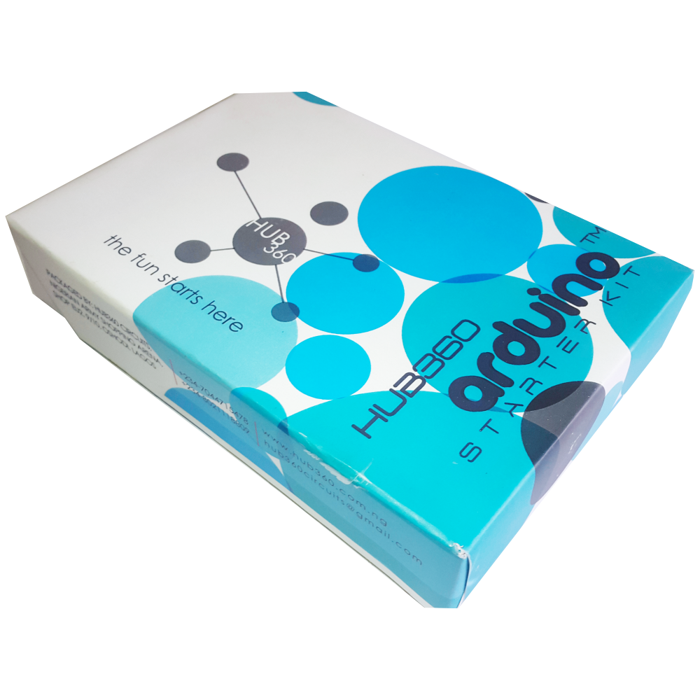
The Hub360 Arduino Starter Kit is a comprehensive package designed for beginners and enthusiasts looking to dive into the world of electronics and programming. This kit includes Arduino Uno, which is a microcontroller board based on the ATmega328P. The kit provides a variety of components and modules to help users learn and experiment with different electronic projects and concepts.
Key Features:
- Includes Arduino Uno board
- Comprehensive set of components and modules for various projects
- Ideal for beginners and hobbyists
- Detailed tutorial and project guide included
- USB interface for easy programming and power
- Compatible with Arduino IDE and various libraries
Technical Specifications:
- Microcontroller: ATmega328P
- Operating Voltage: 5V
- Input Voltage (recommended): 7-12V
- Digital I/O Pins: 14 (6 PWM outputs)
- Analog Input Pins: 6
- DC Current per I/O Pin: 20mA
- Flash Memory: 32KB (ATmega328P) of which 0.5KB used by bootloader
- SRAM: 2KB (ATmega328P)
- EEPROM: 1KB (ATmega328P)
- Clock Speed: 16 MHz
Kit Contents:
- ARDUINO BOARD 1
- ARDUINO USB CABLE 1
- ARDUINO BATTERY CONNECTOR 1
- 400 HOLE BREADBOARD 1
- LED (RED, YELLOW , GREEN, WHITE) 20
- RGB LED 1
- JUMPER WIRE(M-M, M-F, F-F) 120
- PHOTORESISTOR (LDR) 3
- MALE HEADERS 40
- ULTRASONIC SENSOR 1
- FLAME SENSOR 1
- TEMP./HUMIDITY SENSOR 1
- TILT SENSOR 1
- LASER SENSOR 1
- PIR MOTION SENSOR 1
- RESISTORS(220K, 1K, 10K,100K) 40
- 7 SEGMENT DISPLAY 1
- SG90 SERVO 1
- REMOTE CONTROL 1
- BUZZER 1
- 2N2222 2
- TSOP 1838 1
- RF TRANSMITTER 1
- RF RECEIVER 1
- TACT SWITCH 5
- 16*2 LCD DISPLAY
Applications:
- Learning basic electronics and programming
- Building interactive projects and prototypes
- Developing skills in microcontroller-based design
- Experimenting with sensors and actuators
- Creating DIY electronic devices
Usage:
- Setup:
- Connect the Arduino Uno board to your computer using the USB cable.
- Install the Arduino IDE and configure it to recognize the board.
- Programming:
- Write or upload sample code (sketches) to the Arduino board using the Arduino IDE.
- Utilize the provided components and modules to build and test different circuits.
- Experimentation:
- Follow the detailed tutorials and project guide to create various projects.
- Modify and expand on the sample projects to enhance learning and creativity.
Caution:
- Handle the components carefully to avoid damage.
- Ensure proper connections and polarity to prevent short circuits or component failure.
- Verify the code and circuit connections before powering the board.
Datasheet:
For detailed technical specifications of the Arduino Uno, refer to the Arduino Uno Datasheet.
|
The ACS712 is a current sensor from Allegro Microsystems designed to measure current with a maximum rating of 30A. It provides an analog output voltage that is proportional to the current flowing through the sensor. The ACS712 is widely used in power monitoring, load current measurement, and over-current protection applications due to its high accuracy and ease of integration with microcontrollers and other electronic systems.
Key Features:
- Measures AC and DC current up to 30A
- Provides an analog output voltage proportional to the current
- High accuracy with low offset and temperature drift
- Integrated Hall effect sensor for non-invasive current measurement
- Small size and easy to integrate into various circuits
- On-chip signal conditioning and protection
Technical Specifications:
- Sensor Type: Hall Effect Current Sensor
- Current Range: ±30A (AC or DC)
- Output Voltage Range: Typically 0V to Vcc
- Sensitivity: 66mV/A (typical)
- Operating Voltage: 5V ±5%
- Zero Current Offset Voltage: Vcc/2 (typical)
- Temperature Range: -40°C to +85°C
- Current Measurement Accuracy: ±1.5% of full-scale current (typical)
- Package Type: SOP-8 or similar
Applications:
- Power monitoring and control
- Over-current protection systems
- Load current measurement in power supplies
- Motor current sensing
- Energy monitoring and management
Usage:
- Connect the ACS712 sensor to your microcontroller or development board, ensuring correct connection of the power supply (Vcc, GND) and the output voltage pin.
- Route the current-carrying conductor through the sensor to measure the current.
- Read the analog output voltage, which is proportional to the current, and process it according to your application needs.
- Calibrate the sensor if necessary to ensure accurate current measurement.
Caution:
- Ensure the current flowing through the sensor does not exceed the maximum rating (30A) to avoid damage.
- Properly insulate and protect the sensor and connections to prevent short circuits and ensure safe operation.
- Verify the power supply voltage and connections to avoid incorrect readings or sensor damage.
Datasheet:
For detailed technical specifications, refer to the ACS712 Datasheet.
|
Description:
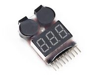
The 1-8S LiPo battery voltage detector with buzzer is an essential tool for monitoring and ensuring the safe operation of lithium polymer (LiPo) batteries used in RC models, drones, and other electronic devices. It provides real-time voltage detection for 1 to 8 series LiPo batteries, alerting users to low voltage conditions with an audible buzzer alarm. This compact device helps prevent over-discharge, which can damage batteries and reduce their lifespan, ensuring optimal performance and safety during use.
Key Features:
- Compatible Battery Types: 1-8S LiPo/Li-ion/LiMn/LiFe
- Voltage Detection Range: 2.7V to 25.2V (1S to 8S)
- Audible Buzzer Alarm: Alerts when voltage drops below preset levels
- Compact and Lightweight: Easy to carry and use in the field
- LED Indicators: Display battery voltage status for quick reference
- Reverse Polarity Protection: Prevents damage due to incorrect battery connection
Technical Specifications:
- Input Voltage: DC 5-27V (powered by the battery being tested)
- Accuracy: ±0.01V
- Operating Temperature: 0°C to 40°C
- Dimensions: Compact and portable design
- Weight: Lightweight for easy handling
Applications:
- RC Models (Cars, Planes, Boats)
- Drones and UAVs (Unmanned Aerial Vehicles)
- Portable Electronic Devices
- Battery Maintenance and Monitoring
|
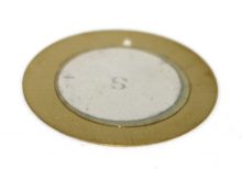
The Piezoelectric Transducer 27mm is a compact and efficient device used for converting electrical signals into mechanical vibrations or sound waves. It is commonly used in buzzers, alarms, and ultrasonic applications due to its ability to generate precise and high-frequency sounds. The transducer is highly reliable, lightweight, and suitable for various electronic projects and devices.
Key Features:
- High Sensitivity: Efficiently converts electrical energy into mechanical vibrations.
- Compact Size: 27mm diameter, suitable for space-constrained applications.
- Wide Frequency Range: Capable of generating a broad range of frequencies.
- Low Power Consumption: Operates efficiently with minimal power.
- Durable Construction: Designed for long-lasting performance.
- Easy Integration: Simple to integrate into various circuits and devices.
Technical Specifications:
- Diameter: 27mm
- Resonant Frequency: Typically around 4 kHz (varies by model)
- Capacitance: Typically 2000 pF at 1 kHz (varies by model)
- Operating Voltage: 3V to 30V (varies by model)
- Sound Pressure Level: Typically 85 dB at 10 cm and 5V (varies by model)
- Operating Temperature Range: -20°C to +60°C
- Material: Metal and ceramic
Applications:
- Buzzers and Alarms: Used in buzzers, alarms, and warning systems.
- Ultrasonic Cleaners: Integrated into ultrasonic cleaning devices.
- Medical Devices: Utilized in medical equipment for ultrasonic applications.
- Sonar Systems: Employed in sonar systems for underwater detection.
- Musical Instruments: Used in electronic musical instruments for sound generation.
- DIY Projects: Suitable for hobbyist and educational electronic projects.
Usage:
- Wiring: Connect the transducer to the appropriate points in your circuit, typically using driver circuits to control the input signal.
- Power Supply: Ensure the transducer is supplied with the correct voltage to prevent damage.
- Mounting: Secure the transducer in place within your device, ensuring it has sufficient space to vibrate freely.
- Testing: Test the transducer by applying the input signal and verifying the sound output or vibration.
Caution:
- Handling: Handle with care to avoid damage to the ceramic element.
- Voltage: Ensure correct voltage levels to avoid overloading the transducer.
- Environmental Conditions: Use within the specified temperature range to maintain performance.
Datasheet:
For detailed technical specifications, refer to the Piezoelectric Transducer 27mm Datasheet.
|
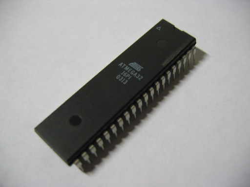
The Atmega 32 is an 8-bit AVR microcontroller from Microchip Technology, known for its high performance and low power consumption. It features a powerful instruction set and a variety of built-in peripherals, making it suitable for a wide range of embedded applications including industrial control, home automation, consumer electronics, and automotive systems.
Key Features:
- 8-bit AVR RISC architecture
- 32 kB of In-System Self-Programmable Flash memory
- 2 kB SRAM for data storage
- 1 kB EEPROM for non-volatile data storage
- 32 general purpose I/O lines
- 3 Timers (2 x 8-bit, 1 x 16-bit)
- 8-channel, 10-bit ADC
- 4 PWM channels
- USART, SPI, and I2C communication interfaces
- Watchdog Timer with separate on-chip oscillator
- On-chip Analog Comparator
- Programmable Serial USART
- Supports external and internal interrupts
- In-System Programming (ISP) via SPI port
- JTAG interface for on-chip debugging
Technical Specifications:
- Package Types: 40-pin PDIP, 44-pin TQFP, 44-pin QFN/MLF
- Operating Voltage: 2.7V to 5.5V
- Clock Speed: Up to 16 MHz
- Flash Memory: 32 kB
- SRAM: 2 kB
- EEPROM: 1 kB
- I/O Pins: 32
- Timers: Two 8-bit, one 16-bit
- ADC Resolution: 10-bit
- ADC Channels: 8
- Operating Temperature Range: -40°C to +85°C
Applications:
- Industrial automation
- Consumer electronics
- Home automation systems
- Automotive applications
- Data acquisition systems
- Robotics
- Security systems
Usage:
- Programming:
- Program the Atmega 32 using a compatible programmer or development kit.
- Utilize ISP for convenient in-system programming.
- Peripheral Configuration:
- Configure I/O pins, timers, ADC, PWM, and communication interfaces via software.
- Use the integrated peripherals to interface with sensors, actuators, and other devices.
- Application Development:
- Write and upload firmware to the microcontroller using development environments such as Atmel Studio.
- Utilize libraries and example codes to speed up the development process.
- Deployment:
- Integrate the programmed microcontroller into your electronic circuit.
- Ensure proper power supply and signal connections to avoid damage and ensure optimal performance.
Caution:
- Handle the microcontroller with care to avoid damage from electrostatic discharge (ESD).
- Verify the correct power supply voltage and connections before powering the device.
- Follow the manufacturer’s guidelines for programming and operation to ensure reliability and longevity.
Datasheet:
For detailed technical specifications, refer to the Atmega 32 Datasheet.
|
Extra long Allen keys, also known as hex keys, are tools used to drive hexagonal socket screws and bolts. Their extended length provides additional leverage and access to hard-to-reach fasteners, making them useful in various mechanical and construction applications. These keys are commonly used in assembly, disassembly, and adjustment tasks where standard-length Allen keys might be insufficient.
Key Features:
- Length: Longer than standard Allen keys, providing extended reach and increased leverage.
- Shape: L-shaped with a hexagonal cross-section.
- Material: Typically made from hardened steel or chrome vanadium for durability and strength.
- Finish: Often coated with corrosion-resistant finishes such as chrome plating.
- Sizes: Available in various sizes, usually ranging from small (e.g., 1.5 mm) to large (e.g., 10 mm).
Technical Specifications:
- Length: Varies, typically ranging from 150 mm to 300 mm or more.
- Material: Hardened steel, chrome vanadium, or similar alloys
- Finish: Chrome-plated or black oxide for corrosion resistance
- Hex Size: Available in various sizes (e.g., 1.5 mm, 2 mm, 3 mm, 4 mm, 5 mm, 6 mm, 8 mm, 10 mm)
- Torque Rating: Dependent on material and design; designed to handle standard mechanical stresses
Applications:
- Automotive: Used for assembling and disassembling parts in vehicles, especially in tight or hard-to-reach areas.
- Machinery: Essential for adjusting and maintaining machinery where extra reach is required.
- Furniture Assembly: Helpful for assembling large furniture pieces with hidden or recessed screws.
- DIY Projects: Ideal for various home improvement and DIY tasks that require reaching deep or recessed fasteners.
- Bicycles: Commonly used in bicycle maintenance and repair, particularly for adjusting components with deep-set screws.
Datasheet:
Extra long Allen keys generally do not have detailed datasheets, but the manufacturer or supplier can provide product specifications.
|
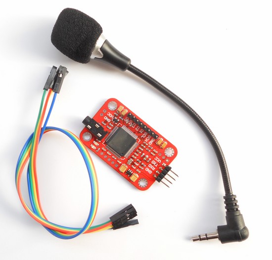
The Voice Recognition Module V3 is a compact and easy-to-use voice recognition module designed for embedded systems. It can be trained to recognize voice commands and respond accordingly, making it ideal for applications in home automation, robotics, and interactive projects. The module supports up to 80 voice commands, with 7 commands being recognized at any given time.
Key Features:
- Supports up to 80 voice commands
- Recognizes 7 voice commands simultaneously
- Speaker-independent and speaker-dependent modes
- Easy UART interface for communication with microcontrollers
- Onboard microphone for voice input
- Low power consumption
- Supports multiple languages
- High accuracy and fast response time
Technical Specifications:
- Supply Voltage: 4.5V to 5.5V
- Current Consumption: 50 mA (max)
- Interface: UART (9600 bps default)
- Recognition Accuracy: 99%
- Recognition Time: < 1 second
- Number of Commands: 80 (in groups of 7)
- Operating Temperature Range: -40°C to +85°C
- Dimensions: 30mm x 20mm x 5mm
Applications:
- Home automation systems
- Voice-controlled robots
- Interactive toys and games
- Voice-activated devices
- Security systems
- Assistive technologies for the disabled
Usage:
- Connection:
- Connect the VCC pin to a 5V power supply.
- Connect the GND pin to ground.
- Connect the RX pin to the TX pin of the microcontroller.
- Connect the TX pin to the RX pin of the microcontroller.
- Training:
- Use the provided software or serial commands to train the module with voice commands.
- Train the module in a quiet environment for best results.
- Store the voice commands in one of the available groups.
- Operation:
- After training, the module can recognize voice commands and send corresponding signals to the microcontroller.
- Use the recognized commands to control devices, trigger actions, or execute programs.
- Programming:
- Write a program on the microcontroller to interface with the module and handle recognized commands.
- Use the UART interface to send and receive data from the module.
Caution:
- Avoid exposing the module to high levels of noise during operation.
- Handle the module carefully to avoid damage from electrostatic discharge (ESD).
- Ensure proper power supply and connections to prevent malfunction.
Datasheet:
For detailed technical specifications, refer to the Voice Recognition Module V3 Datasheet.
|
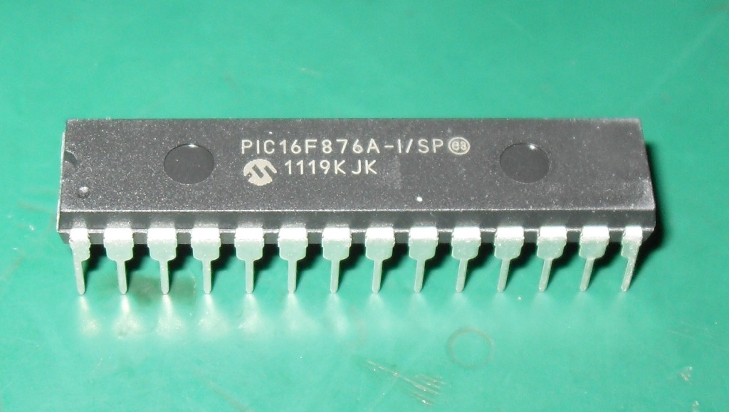
The PIC16F876A is an 8-bit microcontroller from Microchip Technology, known for its versatility and ease of use in a wide range of embedded applications. It features a RISC architecture, with a rich instruction set and extensive peripheral support. This microcontroller is ideal for use in industrial automation, consumer electronics, automotive, and home appliances.
Key Features:
- 8-bit RISC architecture
- 14-bit instruction set
- 7.37 kB (8192 words) Flash memory for program storage
- 368 bytes SRAM for data storage
- 256 bytes EEPROM for non-volatile data storage
- 22 I/O pins for interfacing with external devices
- 3 Timers (2 x 8-bit, 1 x 16-bit)
- 10-bit ADC with 8 channels
- Capture/Compare/PWM (CCP) modules
- Enhanced USART module for serial communication
- Master Synchronous Serial Port (MSSP) supporting SPI and I2C
- Watchdog Timer with dedicated on-chip RC oscillator
- Programmable code protection
- In-Circuit Serial Programming (ICSP) via two pins
Technical Specifications:
- Package Types: 28-pin PDIP, SOIC, SSOP, QFN
- Operating Voltage: 2.0V to 5.5V
- Clock Speed: Up to 20 MHz
- Flash Memory: 7.37 kB
- SRAM: 368 bytes
- EEPROM: 256 bytes
- I/O Pins: 22
- Timers: Two 8-bit, one 16-bit
- ADC Resolution: 10-bit
- ADC Channels: 8
- Operating Temperature Range: -40°C to +85°C
Applications:
- Industrial automation
- Consumer electronics
- Automotive control systems
- Home appliances
- Security systems
- Data acquisition systems
- Robotics
Usage:
- Programming:
- Program the PIC16F876A using a compatible programmer or development kit.
- Utilize ICSP for convenient in-circuit programming and debugging.
- Peripheral Configuration:
- Configure I/O pins, timers, ADC, CCP modules, and communication interfaces via software.
- Use the integrated peripherals to interface with sensors, actuators, and other devices.
- Application Development:
- Write and upload firmware to the microcontroller using development environments such as MPLAB X IDE.
- Utilize libraries and example codes to speed up the development process.
- Deployment:
- Integrate the programmed microcontroller into your electronic circuit.
- Ensure proper power supply and signal connections to avoid damage and ensure optimal performance.
Caution:
- Handle the microcontroller with care to avoid damage from electrostatic discharge (ESD).
- Verify the correct power supply voltage and connections before powering the device.
- Follow the manufacturer’s guidelines for programming and operation to ensure reliability and longevity.
Datasheet:
For detailed technical specifications, refer to the PIC16F876A Datasheet.
|
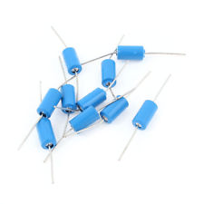
The Tilt Sensor (Blue) is a versatile sensor designed to detect the angle of inclination or tilt in various applications. It uses a mercury switch or a ball-and-cup mechanism to detect changes in orientation. This sensor is commonly used in electronics projects, robotics, and systems where tilt detection is crucial for proper functioning or safety.
Key Features:
- Detection Mechanism: Mercury switch or ball-and-cup mechanism
- Output Type: Digital (Normally open or closed switch)
- Operating Voltage: 3V to 12V DC
- Sensitivity: Detects tilt at various angles (typically ±45°)
- Response Time: Instantaneous response to tilt changes
- Indicator: Blue color for easy identification
- Durability: Reliable and robust for various applications
Technical Specifications:
- Dimensions:
- Sensor Diameter: 25 mm
- Height: 10 mm
- Weight: Approximately 10 g
- Operating Voltage: 3V to 12V DC
- Output Type: Digital (On/Off switch)
- Tilt Angle: ±45° (varies by model)
- Response Time: Immediate (depends on tilt angle)
- Material: Plastic housing with internal tilt mechanism
- Cable Length: 15 cm (typically, varies by supplier)
Applications:
- Robotics: Detects the tilt of a robot to trigger actions or adjust orientation.
- Safety Systems: Used in devices to detect accidental tilting or tipping.
- Consumer Electronics: Helps in features that adjust based on the device’s tilt.
- Automotive: Used in vehicles for tilt detection and stability control.
- Games and Toys: Provides tilt-sensitive controls in gaming or interactive toys.
Datasheet:
For detailed technical information, refer to the Tilt Sensor (Blue) Datasheet.
|
The Inductive Metal Sensor SNO4 is a high-precision sensor designed for detecting the presence of metallic objects through electromagnetic induction. This sensor is ideal for applications in automation and industrial processes where non-contact metal detection is required. It is robust, reliable, and suitable for use in various environments, making it a popular choice for industrial and engineering applications.
Key Features:
- Detection Method: Electromagnetic induction
- Sensing Range: Typically 4 mm for metal objects
- Output Type: NPN or PNP (depending on model)
- Operating Voltage: 10-30V DC
- Response Time: Fast response for accurate detection
- Durability: Designed for industrial environments
- Housing Material: Usually metal or high-quality plastic
Technical Specifications:
- Dimensions:
- Sensor Diameter: 12 mm
- Length: 40 mm
- Weight: Approximately 20 g
- Operating Voltage: 10-30V DC
- Detection Range: Up to 4 mm (for iron)
- Output Type:
- NPN: Normally open or normally closed
- PNP: Normally open or normally closed
- Response Time: <1 ms
- Operating Temperature Range: -25°C to +75°C
- Cable Length: 1.5 meters (typically, varies by supplier)
- Connector Type: Cable or connector (depends on model)
Applications:
- Automation: Used in automated systems for detecting the presence or absence of metal objects.
- Manufacturing: Ideal for quality control and detection of metal parts on production lines.
- Robotics: Helps in obstacle detection and metal part positioning in robotic systems.
- Safety Systems: Integrated into safety systems to ensure proper operation and prevent collisions.
- Industrial Processes: Used in various industrial processes for metal detection and monitoring.
Datasheet:
For detailed technical information, refer to the Inductive Metal Sensor SNO4 Datasheet.
|
The P87C51 is an 8-bit microcontroller from the MCS-51 family, widely used in embedded systems and applications requiring control and automation. It features a robust set of peripherals and is compatible with the standard 8051 instruction set, making it suitable for various industrial, consumer, and automotive applications.
Key Features:
- 8-bit microcontroller based on the MCS-51 architecture
- 4KB of in-system programmable ROM
- 128 bytes of on-chip RAM
- 32 programmable I/O lines
- Two 16-bit timer/counters
- Full-duplex UART for serial communication
- On-chip oscillator and clock circuitry
- Interrupt support with two priority levels
- Watchdog timer for system reliability
- Low-power idle and power-down modes
Technical Specifications:
- CPU: 8-bit 8051 core
- ROM: 4KB
- RAM: 128 bytes
- EEPROM: None (external EEPROM can be used if needed)
- I/O Pins: 32 (four 8-bit ports)
- Timers/Counters: Two 16-bit
- Serial Communication: UART
- Operating Voltage: 4.0V to 5.5V
- Clock Frequency: Up to 24 MHz
- Power Consumption: Low power modes available
- Operating Temperature Range: -40°C to +85°C
- Package Type: DIP-40, PLCC-44, or QFP-44
Applications:
- Industrial control systems
- Consumer electronics
- Automotive systems
- Home automation
- Robotics
- Data acquisition systems
Usage:
- Program the P87C51 using an appropriate programmer with the desired firmware.
- Connect the necessary peripherals and sensors to the microcontroller’s I/O pins.
- Configure the microcontroller’s settings and features via software.
- Integrate the microcontroller into your electronic circuit for specific tasks and control functions.
Caution:
- Ensure proper handling and storage to avoid damage from electrostatic discharge (ESD).
- Verify correct power supply voltage and connections before powering the device.
- Follow the manufacturer’s guidelines for programming and operation.
Datasheet:
For detailed technical specifications, refer to the P87C51 Datasheet.
|
