|
Description |
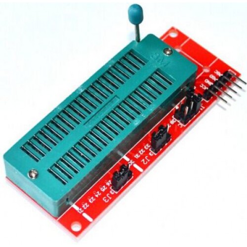
The PIC Kit Programming Adapter is a versatile tool designed to facilitate the programming and debugging of Microchip PIC microcontrollers. It serves as an interface between the PIC microcontroller and a compatible PIC programmer, such as the PICkit 3 or PICkit 4. This adapter simplifies the connection process and supports various PIC microcontroller packages, making it an essential tool for developers working with PIC devices.
Key Features:
- Compatible with PICkit 2, PICkit 3, and PICkit 4 programmers
- Supports various PIC microcontroller packages (DIP, SOIC, SSOP, etc.)
- Provides easy and reliable connection to PIC microcontrollers
- Includes ZIF (Zero Insertion Force) socket for quick and easy microcontroller insertion and removal
- Breakout board with labeled pins for clear identification
- Durable and compact design
Technical Specifications:
- Compatibility: PICkit 2, PICkit 3, PICkit 4, and other Microchip programmers
- Socket Type: ZIF (Zero Insertion Force) socket
- Supported Packages: DIP, SOIC, SSOP, and more (varies by adapter model)
- Pin Headers: Labeled for easy identification
- Power Supply: Via PIC programmer (typically 5V)
- Dimensions: Varies by model (common sizes: 100mm x 50mm x 20mm)
- Weight: Varies by model (typically 50g to 100g)
Applications:
- Programming and debugging PIC microcontrollers
- Development and testing of PIC-based projects
- Educational and research purposes
- Embedded system development
Usage:
- Connect the PIC Kit Programming Adapter to the PIC programmer using the provided cable.
- Insert the PIC microcontroller into the ZIF socket, ensuring correct orientation.
- Connect the PIC programmer to your computer and open the programming software.
- Select the appropriate microcontroller model and load the firmware or code.
- Program or debug the microcontroller as needed.
Caution:
- Ensure correct orientation and insertion of the microcontroller to avoid damage.
- Verify all connections are secure before programming.
- Follow the manufacturer’s guidelines for programming and operation.
Datasheet:
For detailed technical specifications, refer to the PIC Kit Programming Adapter Datasheet.
|
The 30cm Arduino Nano Cable is a compact, high-quality cable designed for connecting Arduino Nano boards to various peripherals or devices. Its short length makes it ideal for use in tight spaces or small projects where a longer cable might be cumbersome. This cable is typically used for programming the Arduino Nano or for connecting it to external components such as sensors, displays, or other microcontrollers.
Key Features:
- Length: 30 cm
- Connector Type: Compatible with Arduino Nano boards
- Connector Style: USB Type-B (or other variants depending on the model)
- Durability: High-quality construction for reliable performance
- Compatibility: Designed to fit Arduino Nano board pinouts
- Color: Varies by manufacturer
Technical Specifications:
- Cable Length: 30 cm
- Connector Type: USB Type-B to USB Type-A (or other variant as applicable)
- Material: Typically copper conductors with PVC insulation
- Data Transfer Rate: Depends on USB standard (usually USB 2.0)
- Operating Temperature Range: -20°C to +60°C
Applications:
- Connecting Arduino Nano boards to PCs for programming and communication
- Linking Arduino boards with external devices or peripherals
- Ideal for use in compact or portable projects where space is limited
Usage:
- Plug the USB Type-B connector into the Arduino Nano board.
- Connect the other end to a PC or other USB-enabled device.
- Ensure proper connection for reliable data transfer and device communication.
Caution:
- Avoid excessive bending or twisting of the cable to prevent damage.
- Ensure connectors are properly aligned before inserting to avoid physical damage.
- Use the cable within the specified temperature range to maintain performance.
Datasheet:
For detailed technical specifications, refer to the 30cm Arduino Nano Cable Datasheet.
|
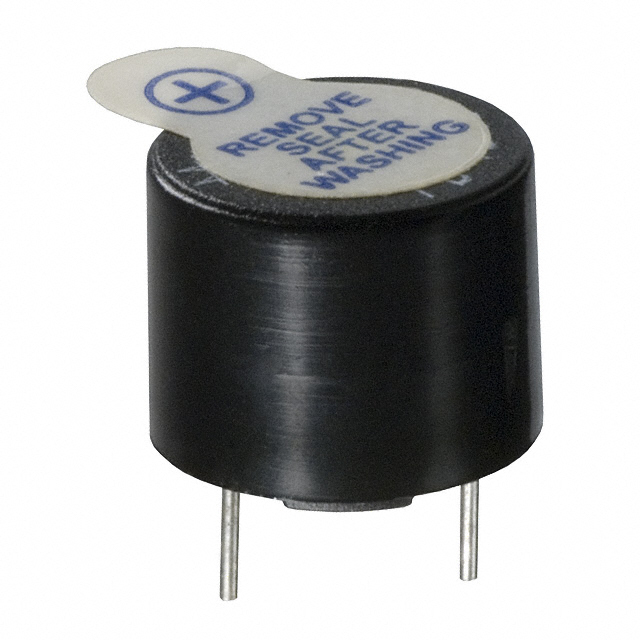
A passive buzzer is an audio signaling device that produces sound through an external oscillating signal. Unlike an active buzzer, which generates sound with an internal oscillator, a passive buzzer requires an external signal to produce sound. This type of buzzer is commonly used in various electronic projects and devices for alarms, notifications, and sound effects.
Key Features:
- Requires external oscillating signal for sound generation
- Produces a wide range of frequencies (depending on the input signal)
- Compact and lightweight design
- Easy to integrate into electronic circuits
- Low power consumption
Technical Specifications:
- Type: Passive Buzzer
- Operating Voltage: Typically 3V to 12V (varies by product)
- Frequency Range: 1kHz to 10kHz (depends on external signal)
- Sound Pressure Level: Typically 85dB at 10cm (varies by product)
- Current Consumption: Typically 10mA to 30mA (depends on voltage and signal)
- Dimensions: Varies by product (commonly around 12mm diameter, 8mm height)
- Operating Temperature Range: -20°C to +70°C (varies by product)
- Mounting Type: Through-hole or surface mount
Applications:
- Alarm and notification systems
- Timers and clocks
- Electronic toys and games
- Sound effects in various devices
- Prototyping and DIY projects
Usage:
- Connect the passive buzzer to your microcontroller or signal generator circuit.
- Provide an oscillating signal (square wave) to the buzzer’s input pin to generate sound. The frequency of the signal determines the pitch of the sound.
- Adjust the signal frequency and duty cycle to achieve the desired sound output.
- Ensure the power supply voltage is within the specified operating range to avoid damage to the buzzer.
Caution:
- Ensure the input signal frequency is within the buzzer’s specified range to avoid distortion or damage.
- Verify the power supply voltage to prevent overvoltage conditions.
- Handle the buzzer carefully to avoid damage to the delicate internal components.
Datasheet:
For detailed technical specifications, refer to the specific product datasheet provided by the manufacturer.
|
The PLC44 to DIP40 IC Socket Adapter is designed to convert a 44-pin PLCC (Plastic Leaded Chip Carrier) IC package into a 40-pin DIP (Dual Inline Package) socket configuration. This adapter enables the use of PLCC ICs in DIP socket-compatible PCBs and prototyping setups, simplifying integration and testing.
Key Features:
- Convenient Conversion: Adapts a 44-pin PLCC IC for use with a 40-pin DIP socket.
- High-Quality Construction: Built with durable materials to ensure reliable connections and longevity.
- Gold-Plated Contacts: Provides excellent conductivity and corrosion resistance.
- Compact Form Factor: Suitable for use with standard breadboards and PCB mountings.
- Easy Installation: Allows for quick and straightforward installation and removal of ICs.
Technical Specifications:
- Package Type: PLC44 to DIP40
- Pin Pitch (PLCC): 1.27mm
- Pin Pitch (DIP): 2.54mm
- Material: FR4 PCB, Gold-plated contacts
- Dimensions: Varies by model
- Weight: Lightweight design
- Temperature Range: -40°C to +85°C
- Mounting Type: Through-hole
Applications:
- Prototyping: Enables the use of PLCC ICs on DIP-compatible breadboards and prototype boards.
- Development: Facilitates the integration of PLCC devices into DIP-based circuit designs.
- Repair and Replacement: Useful for adapting PLCC ICs in existing DIP-based systems or repairs.
- Educational Use: Ideal for demonstrating the use and conversion of different IC package types.
|
The IR2103PBF is a high voltage, high-speed power MOSFET and IGBT driver with independent high and low side referenced output channels. It is designed to drive high-side and low-side N-channel power MOSFETs or IGBTs in a half-bridge configuration. The device features a floating channel designed for bootstrap operation, allowing it to drive the high-side switch up to 600V.
Key Features:
- Gate drive supply range from 10V to 20V
- Floating channel can be used to drive an N-channel power MOSFET or IGBT in the high-side configuration up to 600V
- Gate drive outputs: 2A peak source, 2A peak sink
- Independent high-side and low-side channels
- Under-voltage lockout for both channels
- Logic input (IR2103) compatible with standard CMOS or LSTTL outputs
- Matched propagation delay for both channels
- Low side output in phase with input signal
- High side output out of phase with input signal
Technical Specifications:
- Supply Voltage (Vcc): 10V – 20V
- Floating Supply Voltage (Vb): up to 600V
- Logic Supply Voltage (Vss): -5V – 20V
- Output Source Current (Io+): 2A
- Output Sink Current (Io-): 2A
- Gate Drive Output Voltage (Vout): 10V – 20V
- Propagation Delay: 120ns (typical)
- Operating Temperature Range: -40°C to +125°C
- Package: PDIP-8
Applications:
- Motor drive applications
- Induction heating
- UPS systems
- DC-DC converters
- Switch-mode power supplies
Datasheet:
For detailed technical information, please refer to the IR2103PBF Datasheet.
|
NetPremise® is a data traffic extender that utilizes the existing electrical wiring/cables in a building (homes, hotels, offices, etc) to transmit data at high speeds of no less than **0Mbps (Megabits Per Second) up to distance of **0meters, and emits lossless data signals wirelessly or via Ethernet Ports located on the device.
Why NetPremise?
- Cost Reduction & Time Savings: Because NetPremise is a Powerline Communication Device (i.e. it utilizes already existing electrical wiring in a building), capital investment in procurement and installation of network and structural data cables is not required, thereby saving at least *0% of the time and effort required to install additional network infrastructure.
- Affordable: NetPremise is cheaper than all other network routers and extenders which essentially do not offer NetPremise’s intrinsic value.
- Lossless Data Transmission: Unlike other Wi-Fi range extenders, NetPremise’s signal cannot be disrupted by walls and other obstructions.
- Awards & Recognition: NetPremise® won the award for Best Innovative IT Product in November ***6 at the Nigeria Innovation Summit.
- Quality: Purchase of NetPremise comes with a one (1) year warranty.
- User Friendliness: NetPremise is a plug and play device, no rewiring or PVC trunking is required.
- Support: We are an indigenous Nigerian company inspired by our commitment to add immense value to our clients; NetPremise is proprietary and as such we offer onsite and remote support, with the capability to resolve all technical and non-technical challenges with the product.
|
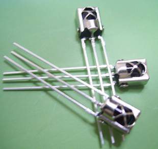
The TSOP 1838 is a compact IR (Infrared) receiver module designed for use in remote control systems. It can detect modulated IR signals at 38 kHz, making it ideal for applications such as remote control reception, IR data transmission, and IR-based communication systems. The TSOP 1838 provides high sensitivity and reliable performance in a small package.
Key Features:
- Pin diode and preamplifier in one package
- Modulated IR signal detection at 38 kHz
- High sensitivity and excellent noise immunity
- Low power consumption
- TTL and CMOS compatible output
- Internal filter for PCM frequency
- Improved shielding against electrical field disturbance
- Suitable for continuous and burst data transmission
Technical Specifications:
- Carrier Frequency: 38 kHz
- Supply Voltage: 2.7V to 5.5V
- Supply Current: 0.4 mA (typical)
- Peak Wavelength: 940 nm
- Reception Range: Up to 45 meters (with proper IR transmitter)
- Viewing Angle: ±45 degrees
- High-Level Output Voltage: ≥ Vcc – 0.2V
- Low-Level Output Voltage: ≤ 0.2V
- Output Pulse Width: Typically 400 µs
- Operating Temperature Range: -25°C to +85°C
- Package Type: 3-pin epoxy package
Applications:
- IR remote control systems
- Consumer electronics (TVs, VCRs, DVDs, audio equipment)
- Home automation
- IR data communication
- Infrared object detection
- Robotics
Usage:
- Connection:
- Connect the Vcc pin to a power supply (2.7V to 5.5V).
- Connect the GND pin to ground.
- Connect the OUT pin to the input of a microcontroller or other logic-level input device.
- Operation:
- When an IR signal at 38 kHz is received, the OUT pin goes low.
- When no IR signal is received, the OUT pin stays high.
- Use the output signal to control devices or process the data using a microcontroller.
- Interfacing:
- Interface the TSOP 1838 with a microcontroller to decode the received IR signals.
- Implement software to process the decoded IR signals for controlling various devices.
Caution:
- Ensure the IR receiver is not exposed to direct sunlight or strong ambient light sources, as this may affect its performance.
- Handle the module with care to avoid damage from electrostatic discharge (ESD).
Datasheet:
For detailed technical specifications, refer to the TSOP 1838 Datasheet.
|
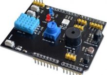
The 9 in 1 multifunctional expansion shield is designed to provide a versatile and convenient interface for microcontroller boards, such as Arduino. It integrates multiple functionalities into a single shield, allowing users to easily expand the capabilities of their microcontroller projects with minimal wiring and setup.
Key Features:
- Versatility: Combines multiple functions into one shield, reducing the need for additional components.
- Ease of Use: Simplifies the process of adding multiple functionalities to your project.
- Compatibility: Designed to be compatible with popular microcontroller platforms, such as Arduino.
Integrated Functions:
- Relay Module: Control high voltage devices with a relay switch.
- Button Inputs: Multiple push buttons for user input.
- LED Indicators: Multiple LEDs for status indication and visual feedback.
- Temperature Sensor: Integrated sensor for temperature measurement.
- Light Sensor: Detect ambient light levels.
- Buzzer: Sound output for alarms or notifications.
- Potentiometer: Adjustable resistance for analog input.
- I2C Interface: Connect additional I2C devices.
- UART Interface: Serial communication with other devices.
Technical Specifications:
- Relay Module: Typically supports up to 10A at 250V AC or 30V DC
- LED Indicators: Standard LEDs for status indication
- Temperature Sensor: Integrated temperature sensor (e.g., LM35 or similar)
- Light Sensor: Photodiode or similar light-detecting component
- Buzzer: Small piezoelectric buzzer for sound output
- Potentiometer: Adjustable knob for varying resistance
- I2C Interface: Standard I2C pins for connecting external devices
- UART Interface: TX/RX pins for serial communication
Applications:
- Prototyping: Ideal for rapid prototyping of microcontroller projects.
- Education: Useful for teaching and learning about microcontroller interfaces and sensors.
- DIY Projects: Great for hobbyists building custom electronics projects.
- Home Automation: Suitable for creating smart home devices with multiple inputs and outputs.
- Robotics: Useful in robotics projects requiring multiple sensors and actuators.
Datasheet:
For detailed technical information, refer to the 9 in 1 Multifunctional Expansion Shield datasheet provided by the manufacturer.
|
Description:
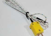
This thermocouple probe is designed for accurate temperature measurement in the range of -50°C to 400°C (-58°F to 752°F). It consists of a fine gauge wire made from two dissimilar metals (usually chromel and alumel for Type K thermocouples), which generate a voltage proportional to the temperature difference between the measurement junction and the reference junction. The probe is constructed with high-quality materials to ensure durability and reliability in various industrial, laboratory, and HVAC applications.
Key Features:
- Type: K thermocouple (common for general-purpose applications)
- Temperature Range: -50°C to 400°C (-58°F to 752°F)
- Probe Length: Standard lengths available, such as 1 meter (custom lengths may be available)
- Fast response time
- High accuracy and repeatability
- Suitable for harsh environments and high-temperature applications
- Flexible and easy to install
- Compatible with standard thermocouple connectors
Technical Specifications:
- Type: K thermocouple (other types available depending on application)
- Temperature Range: -50°C to 400°C (-58°F to 752°F)
- Accuracy: Typically ±1.5°C or ±0.4% (whichever is greater)
- Probe Diameter: Standard diameters available, typically 0.5 mm to 6 mm
- Response Time: Typically within a few seconds
- Sheath Material: Stainless steel, Inconel, or other suitable alloys
- Connection Type: Standard thermocouple connector, such as miniature thermocouple plugs or sockets
Applications:
- Industrial Temperature Monitoring
- HVAC (Heating, Ventilation, and Air Conditioning)
- Food Processing and Refrigeration
- Laboratory Testing and Calibration
- Process Control Systems
- Automotive and Aerospace
Datasheet:
For detailed technical information, refer to the datasheet
|
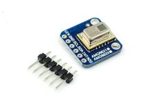
The GY-AMG8833 is an 8×8 infrared thermal imager array temperature sensor module. It utilizes a grid of 64 IR thermal sensors to detect temperature variations across a wide field of view, making it suitable for thermal imaging applications.
Key Features:
- Sensor Type: Infrared thermal imager array.
- Resolution: 8×8 pixel grid (64 pixels in total).
- Temperature Detection: Detects temperature variations across the array.
- Output: Digital temperature values or thermal images.
- Field of View: Wide field of view for comprehensive thermal sensing.
- Refresh Rate: Typically supports high refresh rates for real-time thermal monitoring.
- Integration: Compact module designed for easy integration into various systems.
- Communication: Typically communicates via I2C interface.
- Operating Voltage: Usually operates at 3.3V or 5V DC.
- Adjustability: May include settings for temperature thresholds or image processing.
Technical Specifications:
- Dimensions: Compact size suitable for integration into IoT devices and thermal imaging systems.
- Operating Range: Suitable for indoor and controlled outdoor environments.
- Operating Temperature: Typically -20°C to +80°C.
- Accuracy: High accuracy in temperature detection.
- Power Consumption: Low power consumption, suitable for battery-powered applications.
Applications:
- Thermal imaging cameras
- Temperature monitoring systems
- Industrial process monitoring
- IoT devices requiring thermal sensing capabilities
Datasheet:
For detailed technical information, refer to the GY-AMG8833 datasheet.
|
The DHT21 AM2301 is a digital temperature and humidity sensor designed for accurate and reliable measurement of environmental conditions. It provides calibrated digital output, ensuring ease of integration into a variety of applications, such as HVAC systems, weather stations, and IoT projects. The sensor combines a capacitive humidity sensor and a thermistor, offering long-term stability and high precision.
Key Features:
- High accuracy and stability
- Calibrated digital output
- Low power consumption
- Long-term stability
- Easy to integrate and use
- Compact and robust design
Technical Specifications:
- Humidity Range: 0% to 100% RH
- Humidity Accuracy: ±3% RH (typical)
- Temperature Range: -40°C to +80°C
- Temperature Accuracy: ±0.5°C (typical)
- Operating Voltage: 3.3V to 5.5V
- Signal Output: Digital (single-bus)
- Dimensions: 59mm x 12mm x 12mm
- Weight: 15g
- Power Consumption: 1-1.5mA (average), 2.5mA (max)
- Response Time: 2 seconds (typical)
- Cable Length: 23cm (standard)
Applications:
- HVAC Systems: Used for monitoring and controlling temperature and humidity in heating, ventilation, and air conditioning systems.
- Weather Stations: Integrated into weather stations for environmental data collection.
- IoT Projects: Suitable for smart home devices and other IoT applications.
- Agricultural Monitoring: Used in greenhouses and agricultural environments to maintain optimal growing conditions.
- Industrial Automation: Applied in industrial settings for environmental monitoring and control.
Datasheet:
For detailed technical information, refer to the DHT21 AM2301 Temperature and Humidity Sensor Datasheet provided by the manufacturer.
|
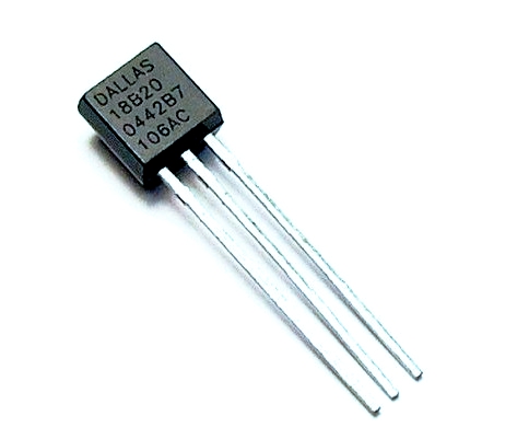
The DS18B20 is a digital temperature sensor from Maxim Integrated, designed for accurate temperature measurement in a wide range of applications. It features a 1-Wire communication protocol, allowing multiple sensors to be connected to a single data line. This sensor provides high-resolution temperature data and is ideal for use in temperature monitoring systems, data loggers, and embedded applications.
Key Features:
- Digital temperature sensor with 1-Wire interface
- High accuracy and resolution
- Wide temperature range from -55°C to +125°C
- Programmable resolution (9 to 12 bits)
- Unique 64-bit serial code for identification
- Low power consumption
- Waterproof versions available for harsh environments
- Easy to interface with microcontrollers and digital systems
Technical Specifications:
- Sensor Type: Digital temperature sensor
- Communication Protocol: 1-Wire
- Temperature Range: -55°C to +125°C
- Accuracy: ±0.5°C from -10°C to +85°C
- Resolution: 9 to 12 bits (programmable)
- Operating Voltage: 3.0V to 5.5V
- Current Consumption: 1mA (active), 750µA (standby)
- Operating Temperature Range: -55°C to +125°C
- Package Type: TO-92, waterproof probe (varies by model)
Applications:
- Temperature measurement in various environments
- Data logging and environmental monitoring
- Home automation and HVAC systems
- Industrial temperature control
- Scientific research and prototyping
Usage:
- Connect the DS18B20 Temperature Sensor to your microcontroller or development board using the 1-Wire interface (data, Vcc, and GND).
- Power the sensor with a compatible voltage (3.0V to 5.5V).
- Use the appropriate 1-Wire library or driver to interface with the sensor and configure the resolution.
- Read temperature data and use it as needed for your application.
Caution:
- Ensure proper wiring and power supply to avoid malfunction.
- Handle the sensor carefully, especially if using the waterproof version, to avoid damaging the probe.
- Verify connections and use the appropriate libraries for accurate temperature readings.
Datasheet:
For detailed technical specifications, refer to the DS18B20 Datasheet.
|
The Arduino Nano V3.0 is a compact, breadboard-friendly microcontroller board based on the ATmega328P. It is part of the Arduino platform and is designed for use in small projects and prototyping. The board includes a USB cable for easy connection to a computer for programming and power.
Key Features:
- ATmega328P microcontroller
- Compact size with 30mm x 18mm dimensions
- 22 digital I/O pins, of which 6 can be used as PWM outputs
- 8 analog input pins
- 32 KB Flash memory for program storage
- 2 KB SRAM for data storage
- 1 KB EEPROM for non-volatile data storage
- Built-in USB interface for easy programming
- Compatible with Arduino IDE for development
Technical Specifications:
- Microcontroller: ATmega328P
- Operating Voltage: 5V
- Input Voltage: 7-12V (through the power jack or USB)
- Digital I/O Pins: 22
- PWM Output Pins: 6
- Analog Input Pins: 8
- Flash Memory: 32 KB
- SRAM: 2 KB
- EEPROM: 1 KB
- Clock Speed: 16 MHz
- USB Interface: Mini-USB
- Dimensions: 30mm x 18mm
Applications:
- Prototyping and development for electronics projects
- Embedded systems and automation
- Robotics
- Sensor interfacing and data acquisition
- Educational projects and learning
Usage:
- Connection: Connect the Arduino Nano V3.0 to your computer using the included USB cable. The USB cable is used for both power and programming.
- Programming: Use the Arduino IDE to write and upload code to the board via the USB connection.
- Connection to Peripherals: Utilize the digital and analog I/O pins to connect sensors, actuators, and other peripherals.
- Power Supply: The board can be powered through the USB connection or via an external power source connected to the VIN pin.
Caution:
- Ensure correct voltage levels are used to avoid damaging the board. The recommended input voltage is 7-12V.
- Avoid short-circuiting the pins and connections.
- Handle the board and USB cable with care to prevent physical damage.
Datasheet:
For detailed technical specifications and pin configuration, refer to the Arduino Nano V3.0 Datasheet.
|
The STM32F411CEU6 Development Board is a versatile microcontroller evaluation platform designed for developers working with the STM32F4 series of microcontrollers from STMicroelectronics. This board features the STM32F411CEU6, a high-performance ARM Cortex-M4 microcontroller, offering a wide range of features and peripherals ideal for developing complex embedded systems and applications.
Key Features:
- Microcontroller: STM32F411CEU6 with ARM Cortex-M4 core
- Performance: 100 MHz clock speed, 512 KB Flash memory, and 128 KB SRAM
- Peripheral Support: Includes multiple I/O ports, UART, SPI, I2C, ADC, DAC, and timers
- Connectivity: USB OTG, CAN, and GPIOs for flexible interfacing
- Development Support: Compatible with various development environments and tools, including STM32CubeIDE
- On-Board Features: Debugging and programming interfaces, LEDs, push buttons, and expansion connectors
Technical Specifications:
- Microcontroller: STM32F411CEU6
- Core: ARM Cortex-M4
- Clock Speed: 100 MHz
- Flash Memory: 512 KB
- SRAM: 128 KB
- I/O Pins: Multiple GPIOs with varying configurations
- Peripherals: UART, SPI, I2C, ADC, DAC, Timers, CAN
- Connectivity: USB OTG, CAN
- Operating Voltage: 3.3V
- Development Interface: SWD (Serial Wire Debug) for programming and debugging
- Dimensions: Varies by board design, typically around 70mm x 50mm
Applications:
- Embedded system development
- Prototyping and experimentation
- Industrial automation
- Consumer electronics
- Robotics and control systems
- Educational projects and research
Usage:
- Connect the board to your PC using the USB cable for power and communication.
- Install the necessary drivers and development tools (e.g., STM32CubeIDE).
- Develop and upload firmware to the microcontroller using the integrated development environment (IDE).
- Use the on-board peripherals and expansion connectors for prototyping and testing your application.
Caution:
- Ensure correct power supply voltage (3.3V) to avoid damage to the board.
- Use proper ESD precautions to prevent electrostatic discharge damage.
- Follow the manufacturer’s guidelines for programming and debugging to avoid errors.
- Avoid connecting external voltages directly to the GPIOs without proper interfacing.
Datasheet:
For detailed technical specifications, refer to the STM32F411CEU6 Datasheet.
|
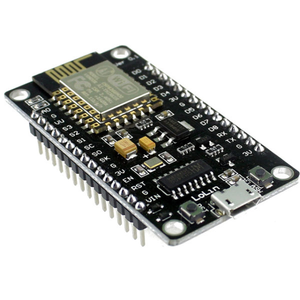
The ESP8266 NodeMcu LUA WiFi Development Board is an open-source IoT platform. It integrates the ESP8266 WiFi module, which allows for easy development of WiFi-based applications. The board includes the Lua scripting language for programming, enabling quick and efficient development. This development board is highly suitable for beginners and professionals looking to build IoT projects due to its simplicity, low cost, and robust capabilities.
Key Features:
- WiFi Module: Integrated ESP8266 with full TCP/IP stack and microcontroller capability
- Programming Language: Lua scripting language support
- GPIO: Multiple GPIO pins available for connecting sensors and actuators
- USB Interface: On-board USB to serial interface for easy programming
- Memory: 4MB Flash Memory
- Power Supply: Can be powered via micro USB or external power supply
- Built-in Antenna: On-board WiFi antenna for wireless connectivity
- Compact Size: Small form factor for easy integration into projects
Technical Specifications:
- Dimensions: 48 mm x 26 mm
- Weight: Approximately 10 g
- Operating Voltage: 3.3V
- Digital I/O Pins: 11
- Analog Input Pins: 1 (max input 3.2V)
- Clock Speed: 80 MHz
- Flash Memory: 4MB
- USB to UART: CP2102 or CH340G
- Power Consumption:
- Deep Sleep: <10 μA
- Light Sleep: <1 mA
- Modem Sleep: ~15 mA
- Active Mode: ~70 mA
- WiFi Standards: 802.11 b/g/n
- Connector Types: Micro USB, GPIO headers
Applications:
- IoT Projects: Ideal for developing Internet of Things applications with WiFi connectivity.
- Home Automation: Control and monitor home appliances and systems remotely.
- Prototyping: Rapid development and testing of WiFi-enabled prototypes.
- Wireless Sensor Networks: Creating networks of sensors with real-time data collection and communication.
- Smart Devices: Integrating WiFi capabilities into various smart devices and gadgets.
Datasheet:
For detailed technical information, refer to the ESP8266 NodeMcu LUA WiFi Development Board Datasheet.
|
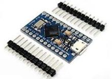
The Arduino Pro Micro is a compact and versatile microcontroller board based on the ATmega32U4 microchip. It is part of the Arduino family and designed for projects where space is limited. The Pro Micro board features built-in USB capabilities, allowing it to emulate a keyboard, mouse, or other USB devices, making it suitable for a wide range of applications including custom input devices and embedded systems.
Key Features:
- Microcontroller: ATmega32U4
- Operating Voltage: 5V
- Input Voltage (recommended): 7-12V
- Digital I/O Pins: 18
- Analog Input Pins: 9
- Flash Memory: 32 KB (ATmega32U4), of which 4 KB used by bootloader
- SRAM: 2.5 KB
- EEPROM: 1 KB
- Clock Speed: 16 MHz
- USB: Built-in USB functionality for direct connection to computers and emulation of USB devices
Technical Specifications:
- Dimensions: 33 mm x 18 mm
- Weight: Approximately 8 g
- Communication: UART, SPI, I2C, USB
- On-board LEDs: TX, RX, Power, and one user-defined LED
- Power:
- DC Current per I/O Pin: 40 mA
- DC Current for 3.3V Pin: 50 mA
- Connectors:
- USB Micro-B for programming and power
- 6-pin header for serial communication
- Pins for additional communication interfaces and power
Applications:
- Custom Input Devices: Can be used to create custom keyboards, mice, and other input devices.
- Embedded Systems: Suitable for small-scale embedded projects where USB connectivity is required.
- Prototyping: Ideal for rapid prototyping and development due to its compact size and USB capability.
- IoT Projects: Can be integrated into Internet of Things (IoT) devices for various control and monitoring applications.
- Wearables: Perfect for wearable electronics and projects requiring a small form factor.
Datasheet:
For detailed technical information, refer to the Arduino Pro Micro Datasheet.
|
The Raspberry Pi 3.5 Inches Resistive Touch Screen is a compact display module designed specifically for use with Raspberry Pi boards. This touch screen offers a user-friendly interface for various applications, allowing you to interact directly with your Raspberry Pi projects. It features a resistive touch panel, making it suitable for applications that require precise touch input.
Key Features:
- Screen Size: 3.5 inches
- Display Type: TFT LCD
- Resolution: 320 x 480 pixels
- Touch Type: Resistive touch panel
- Interface: SPI (Serial Peripheral Interface)
- Compatibility: Compatible with Raspberry Pi models such as Raspberry Pi 4, 3, 2, and Zero
Technical Specifications:
- Screen Size: 3.5 inches
- Display Resolution: 320 x 480 pixels
- Touch Panel: Resistive
- Interface: SPI
- Operating Voltage: 3.3V/5V (powered through Raspberry Pi GPIO)
- Dimensions: Approximately 85mm x 55mm x 30mm
- Viewing Angle: Wide viewing angle
- Backlight: LED backlight for enhanced visibility
Applications:
- Portable Raspberry Pi projects
- DIY handheld devices
- Control interfaces for home automation
- Interactive displays for education and prototyping
- Gaming consoles and entertainment systems
Usage:
- Connect the 3.5-inch touch screen to the GPIO pins of your Raspberry Pi board.
- Install the necessary drivers and configure the Raspberry Pi for the touch screen.
- Calibrate the touch panel if required to ensure accurate touch input.
- Use the touch screen to interact with your Raspberry Pi applications, projects, or operating system.
Caution:
- Handle the touch screen carefully to avoid damaging the display or touch panel.
- Ensure the GPIO pins are correctly connected to avoid short circuits or incorrect operation.
- Follow the manufacturer’s guidelines for driver installation and configuration.
Datasheet:
For detailed technical specifications, refer to the Raspberry Pi 3.5 Inches Resistive Touch Screen Datasheet.
|
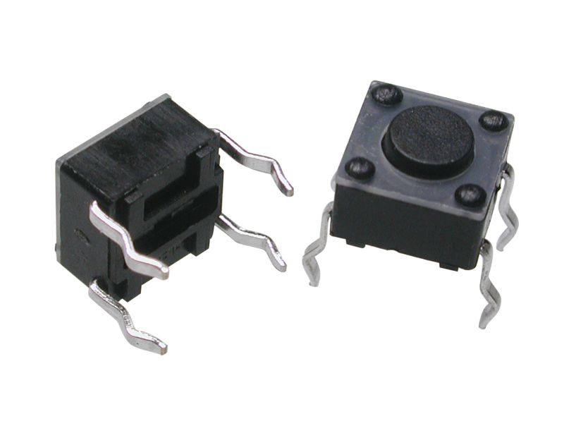
A Tact Switch, also known as a tactile switch, is a type of switch designed to provide a tactile feedback when pressed. These switches are commonly used in electronic devices for user input, such as in keyboards, remote controls, and various consumer electronics. Tact switches are known for their compact size, reliability, and ease of integration into circuits.
Key Features:
- Tactile Feedback: Provides a satisfying click feel when pressed.
- Compact Size: Small and suitable for space-constrained applications.
- Reliability: Durable and designed for a high number of actuation cycles.
- Variety of Sizes: Available in different sizes and heights to fit various designs.
- Easy Mounting: Can be mounted on PCBs with through-hole or surface-mount technology.
- Wide Application Range: Suitable for a variety of electronic devices and applications.
Technical Specifications:
- Contact Rating: Typically 50mA, 12V DC
- Contact Resistance: ≤ 100mΩ
- Insulation Resistance: ≥ 100MΩ at 100V DC
- Dielectric Strength: 250V AC for 1 minute
- Operating Force: Typically 160gf (varies by model)
- Travel: Typically 0.25mm to 0.5mm
- Operating Life: Typically 100,000 to 1,000,000 cycles
- Operating Temperature Range: -20°C to +70°C
Applications:
- Consumer Electronics: Used in remote controls, calculators, and gaming controllers.
- Computer Peripherals: Keyboards, mice, and other input devices.
- Home Appliances: Control panels for microwaves, washing machines, and other appliances.
- Automotive: Control buttons on car dashboards and steering wheels.
- Industrial Equipment: Control panels and user interfaces for machinery.
- DIY Projects: Suitable for custom electronic projects and prototypes.
Usage:
- Mounting: Solder the tact switch onto a PCB, ensuring correct alignment of the pins.
- Wiring: Connect the switch to your circuit, typically using pull-up or pull-down resistors.
- Testing: Verify the switch functionality by pressing it and checking the response in your circuit.
- Integration: Integrate the switch into your final product, ensuring it is accessible and functions as intended.
Caution:
- Debouncing: Implement debouncing in your software to ensure accurate readings.
- Proper Soldering: Avoid excessive heat during soldering to prevent damage to the switch.
- Environmental Conditions: Ensure the switch is used within its specified temperature and humidity range.
Datasheet:
For detailed technical specifications, refer to the Tact Switch Datasheet.
|
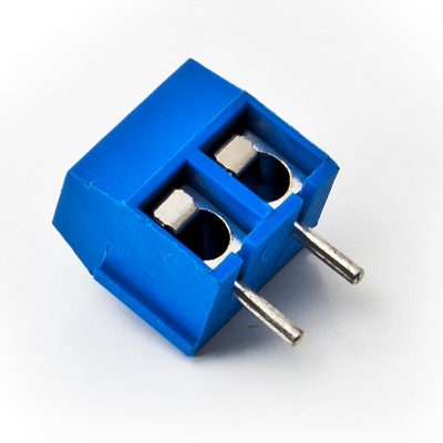
The 2-Way PCB Screw Terminal is a compact and reliable connector used to securely attach and disconnect wires on a printed circuit board (PCB). It features two screw terminals for connecting two wires, providing a stable and durable connection for various electronic and electrical applications. This type of terminal is commonly used in power distribution, signal connections, and modular systems.
Key Features:
- Two screw terminals for easy wire connection
- Suitable for use with PCB for secure mounting
- Provides a reliable and durable electrical connection
- Simple and convenient for quick wire insertion and removal
- Supports various wire gauges and types
- Compact design for space-saving on PCB
Technical Specifications:
- Number of Positions: 2
- Terminal Type: Screw
- Mounting Type: PCB (Printed Circuit Board)
- Wire Gauge Range: Typically 22-12 AWG (varies by manufacturer)
- Insulation Material: Polyamide (PA) or other suitable insulating materials
- Terminal Material: Brass or copper with tin plating
- Operating Voltage: Typically up to 300V (depends on the specific terminal rating)
- Operating Temperature Range: -40°C to +105°C
- Package Type: Typically available in strips or individual connectors
Applications:
- Power supply connections
- Signal wiring and distribution
- Modular and expandable systems
- Industrial equipment
- Consumer electronics
Usage:
- Mount the 2-Way PCB Screw Terminal onto the PCB by inserting it into the designated holes.
- Secure the terminal to the PCB by soldering the pins or using mechanical locking methods (if applicable).
- Strip the insulation from the wires to the appropriate length.
- Insert the stripped wires into the terminal and tighten the screws to secure the wires in place.
Caution:
- Ensure the terminal is rated for the voltage and current levels used in your application.
- Avoid over-tightening the screws to prevent damage to the terminal or wires.
- Verify proper wire insulation stripping to ensure reliable connections.
Datasheet:
For detailed technical specifications, refer to the 2-Way PCB Screw Terminal Datasheet.
|
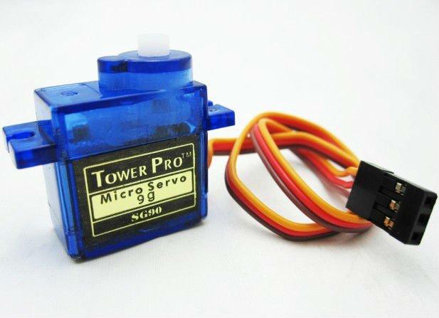
The SG90 is a popular micro servo motor known for its small size, lightweight, and reliable performance. It is ideal for use in RC applications, robotics, and other hobbyist and DIY projects. The servo provides precise control over angular position, speed, and acceleration.
Key Features:
- Lightweight and compact design
- High precision and stable movement
- Nylon gears for smooth operation
- Compatible with most radio control systems
- Easy to interface with microcontrollers
- Includes various servo horns and mounting hardware
Technical Specifications:
- Operating Voltage: 4.8V to 6.0V
- Stall Torque: 1.8 kg/cm (4.8V), 2.2 kg/cm (6.0V)
- Speed: 0.12 sec/60° (4.8V), 0.10 sec/60° (6.0V)
- Rotation Angle: 0° to 180°
- Control System: PWM (Pulse Width Modulation)
- Gear Type: Nylon
- Connector Wire Length: 250mm
- Dimensions: 23mm x 12.2mm x 29mm
- Weight: 9g
Applications:
- RC vehicles (cars, airplanes, boats)
- Robotics
- Mechanical arms and grippers
- Pan/tilt mechanisms for cameras and sensors
- DIY electronics projects
- Animatronics
Usage:
- Connection:
- Connect the VCC (red) wire to a 5V power supply.
- Connect the GND (brown) wire to ground.
- Connect the signal (orange) wire to a PWM output on the microcontroller or servo controller.
- Control:
- Use PWM signals to control the angular position of the servo.
- Adjust the pulse width (typically between 1ms and 2ms) to move the servo to the desired position.
- Mounting:
- Use the included servo horns and mounting hardware to attach the servo to your project.
- Ensure the servo is securely mounted to handle the torque generated during operation.
Caution:
- Avoid stalling the servo for extended periods to prevent overheating.
- Ensure the servo operates within the specified voltage range to avoid damage.
- Handle the servo carefully to prevent damage to the internal gears and motor.
Datasheet:
For detailed technical specifications, refer to the SG90 Servo Datasheet.
|
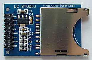
The SD Card Module is a compact and efficient solution for adding storage capabilities to your microcontroller or development board projects. It allows you to read from and write to SD cards, making it ideal for data logging, file storage, and other applications requiring large amounts of memory. The module supports various SD card formats and interfaces seamlessly with popular microcontrollers like Arduino, Raspberry Pi, and others.
Key Features:
- Storage: Supports SD, SDHC, and MicroSD (with adapter) cards
- Interface: SPI interface for easy integration
- Voltage Compatibility: Operates at 3.3V and 5V
- Onboard 3.3V Regulator: Ensures stable operation
- Card Detection: Built-in card detection switch
- Compact Design: Small footprint for easy incorporation into projects
- File System: Compatible with FAT16 and FAT32 file systems
Technical Specifications:
- Supported Cards: SD, SDHC, MicroSD (with adapter)
- Operating Voltage: 3.3V/5V
- Interface: SPI
- Current Consumption: < 100mA
- File System: FAT16, FAT32
- Dimensions: 42mm x 24mm x 12mm
Applications:
- Data Logging: Store sensor data and logs in embedded systems.
- File Storage: Save files for multimedia applications and projects.
- Firmware Updates: Load new firmware from the SD card for microcontrollers.
- DIY Projects: Perfect for hobbyists needing additional storage.
- Educational Projects: Commonly used in learning modules for data storage and retrieval.
Usage:
- Wiring: Connect the SD card module to your microcontroller using the SPI interface (CS, MOSI, MISO, SCK, VCC, GND).
- Power Supply: Ensure the module is powered with 3.3V or 5V, as required.
- Card Insertion: Insert a formatted SD card into the module.
- Programming: Use libraries (e.g., SD library for Arduino) to initialize the SD card and read/write data.
- Data Handling: Store or retrieve data files from the SD card as needed by your application.
Caution:
- Voltage Levels: Ensure proper voltage levels to avoid damaging the module.
- Handling SD Cards: Handle SD cards with care to prevent data loss or corruption.
Datasheet:
For detailed technical specifications, refer to the SD Card Module Datasheet.
|
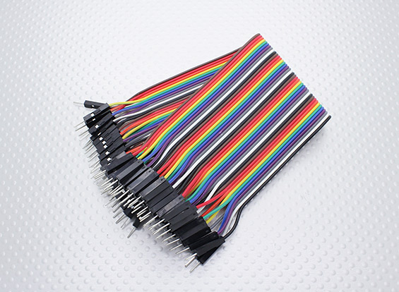
The Male-Male Jumper Wires (Set) is an essential component for breadboarding and prototyping in electronics projects. These wires are used to establish quick and reliable connections between various points in a circuit, such as between the pins of a microcontroller, sensors, modules, and other components. The set typically includes a variety of lengths and colors to help with organizing and identifying connections.
Key Features:
- Easy and quick connections for breadboards and other prototyping environments
- Variety of lengths and colors for flexibility and organization
- Durable and reusable
- Compatible with standard 0.1” (2.54mm) pitch headers
- Ideal for Arduino, Raspberry Pi, and other microcontroller projects
Technical Specifications:
- Connector Type: Male to Male
- Pin Spacing: 0.1” (2.54mm)
- Wire Lengths: Varies (typically 10cm, 20cm, and 30cm)
- Wire Gauge: 24 AWG
- Insulation Material: PVC
- Conductor Material: Copper or copper-clad aluminum
- Colors: Multiple (e.g., red, blue, green, yellow, black, white)
- Quantity: Typically 40 wires per set (may vary)
Applications:
- Breadboarding and prototyping
- Microcontroller and development board projects
- Interfacing sensors and modules
- Educational and DIY electronics projects
- Connecting components in a temporary setup
Usage:
- Connecting Components:
- Use the jumper wires to connect the pins of different components on a breadboard or between header pins on development boards.
- Ensure firm and secure connections by inserting the male ends into the breadboard or header sockets.
- Organizing Circuits:
- Use different colors to identify various connections and signals, making the circuit easier to debug and understand.
- Select appropriate wire lengths to minimize clutter and ensure neat and organized prototyping.
- Reusability:
- Jumper wires can be reused in multiple projects, making them a cost-effective solution for prototyping.
Caution:
- Handle with care to avoid damaging the wire insulation or connectors.
- Ensure correct connections to avoid short circuits or incorrect wiring.
- Store in a dry and cool place to maintain the integrity of the connectors and insulation.
Datasheet:
Refer to the specific manufacturer’s datasheet or product details for more information if available.
|
The Rechargeable Battery 6V 4.5Ah is designed for use in various applications requiring a reliable power source. With its high capacity, it provides consistent and long-lasting power, making it suitable for both portable and stationary devices.
Key Features:
- High Capacity: 4.5Ah provides extended usage time between charges.
- Rechargeable: Designed for multiple charge cycles, offering a cost-effective and sustainable power solution.
- Stable Voltage: Delivers a steady 6V output for reliable performance.
- Versatile Use: Suitable for a wide range of applications, including electronics, alarm systems, and backup power.
Technical Specifications:
- Voltage: 6V
- Capacity: 4.5Ah
- Type: Rechargeable lead-acid battery
Applications:
- Portable electronic devices
- Alarm systems
- Backup power for small devices
- Remote control toys
Usage:
- Connect the battery to the device or charger with compatible connections.
- Ensure proper polarity when connecting to avoid damage.
- Charge the battery according to the manufacturer’s instructions.
- Replace or recharge as needed to maintain optimal performance.
Caution:
- Avoid short-circuiting the battery terminals.
- Store in a cool, dry place.
- Dispose of properly according to local regulations.
|
The APM 2.8 Multicopter Flight Controller is an advanced autopilot system that enhances the capabilities of drones and multicopters. It is an upgraded version of the APM 2.5 and 2.6, featuring a built-in compass and the option to use an external compass via a jumper. This flight controller is ideal for both FPV RC drones and other autonomous vehicles, including multi-rotors, cars, and boats. It is a highly reliable system that has won the prestigious Outback Challenge UAV competition.
Key Features:
- Built-in compass and optional external compass for enhanced navigation
- Onboard 4 MegaByte Dataflash chip for automatic data logging
- Compatible with uBlox LEA-6H GPS module with Compass
- Uses Invensense’s 6 DoF Accelerometer/Gyro MPU-6000
- Upgraded barometric pressure sensor MS5611-01BA03
- Atmel’s ATMEGA2560 for processing and ATMEGA32U-2 for USB functions
- Arduino compatible for easy integration and customization
Technical Specifications:
- Controller Type: APM 2.8
- Built-in Compass: Yes, with jumper option for external compass
- Data Logging: 4 MegaByte Dataflash chip
- GPS Module Compatibility: uBlox LEA-6H (optional)
- Sensors: Invensense MPU-6000 (Accelerometer/Gyro), MS5611-01BA03 (Barometric Pressure)
- Processing Chips: ATMEGA2560 (processing), ATMEGA32U-2 (USB functions)
- Speed At Rated Load: 8.4 in/min
- Voltage: 12 V DC
- Shape: Rectangular
- Humidity Range: 10-95%
Applications:
- Multi-copters and drones
- Autonomous vehicles (cars, boats)
- FPV RC drones
- GPS mission planning and waypoint navigation
Usage:
- Connect the APM 2.8 Flight Controller to your vehicle’s power supply and motors.
- Attach the optional GPS module and configure the built-in compass settings.
- Use Mission Planner software or a compatible ground control station for setup and calibration.
- Perform data logging and adjust settings as needed for your specific application.
Caution:
- Ensure proper calibration of the compass and other sensors before flight.
- Avoid exposure to extreme humidity and ensure the controller is kept within the specified environmental conditions.
- Follow all safety guidelines for UAV operation and comply with local regulations.
|
The 7 Inch Raspberry Pi HDMI Display with Touch is a compact and versatile display designed to provide a high-quality visual interface for Raspberry Pi projects. It features a touchscreen functionality, allowing for intuitive interaction with the operating system and applications. The display connects via HDMI, making it easy to integrate with Raspberry Pi boards and other compatible devices.
Key Features:
- 7-inch display size providing a clear and bright visual interface
- HDMI interface for easy connection to Raspberry Pi and other devices
- Touchscreen functionality for interactive control
- High-resolution display for sharp and detailed images
- Compact design suitable for embedded and portable applications
- Integrated driver board for simplified setup and use
Technical Specifications:
- Display Size: 7 inches (diagonal)
- Resolution: Typically 800 x 480 pixels (varies by model)
- Display Type: TFT LCD
- Touchscreen Type: Capacitive or resistive (depends on model)
- Interface: HDMI (for video signal) and USB (for touch input)
- Viewing Angle: Typically 60°/70°/70°/70° (H/V)
- Brightness: Typically 400-500 nits (depends on model)
- Contrast Ratio: Typically 500:1
- Power Supply: Typically 5V DC via USB or dedicated power input
- Mounting Options: VESA mount compatible (may require additional accessories)
Applications:
- Raspberry Pi projects and DIY electronics
- Portable and embedded systems
- Touchscreen interfaces for custom applications
- Educational projects and demonstrations
- Digital signage and interactive kiosks
Usage:
- Connection: Connect the display to the Raspberry Pi using the HDMI cable for video and the USB cable for touchscreen functionality.
- Power: Ensure the display is powered using the appropriate power source (typically 5V DC).
- Configuration: Configure the display settings on the Raspberry Pi operating system to match the display resolution and orientation.
- Touch Calibration: If necessary, calibrate the touchscreen functionality using the provided calibration software or settings.
Caution:
- Handle the display with care to avoid damage to the screen or connectors.
- Ensure proper power supply to avoid instability or damage to the display.
- Follow the manufacturer’s instructions for installation and configuration to ensure optimal performance.
Datasheet:
For detailed technical specifications, refer to the Display Datasheet .
|
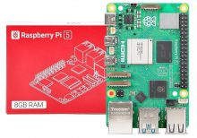
The Raspberry Pi 5 (8GB RAM) is the latest iteration in the Raspberry Pi series, featuring significant performance improvements and expanded memory to handle more demanding applications. With a powerful quad-core processor, enhanced GPU, and versatile connectivity options, this compact single-board computer is ideal for a wide range of projects and applications.
Key Features:
- 8GB RAM: Ample memory for complex tasks and multitasking
- Quad-Core Processor: Enhanced processing power for improved performance
- Enhanced GPU: Supports 4K video output and better graphics performance
- Multiple Connectivity Options: USB 3.0 ports, Gigabit Ethernet, Bluetooth 5.0, and Wi-Fi
- Expandable Storage: MicroSD card slot and USB boot capability
- GPIO Pins: 40-pin GPIO header for hardware projects
Technical Specifications:
- Processor: Quad-core ARM Cortex-A72, 1.8GHz
- Memory: 8GB LPDDR4 RAM
- Graphics: Broadcom VideoCore VI, supports dual 4K displays
- Storage: MicroSD card slot, USB boot support
- Connectivity:
- 2 x USB 3.0 ports
- 2 x USB 2.0 ports
- Gigabit Ethernet
- Dual-band 2.4/5.0 GHz IEEE 802.11ac wireless
- Bluetooth 5.0
- Video Output: 2 x micro HDMI ports (supports up to 4K resolution)
- Audio Output: 3.5mm audio jack, HDMI
- Power Supply: 5V/3A USB-C power input
- GPIO: 40-pin GPIO header
- Operating System: Compatible with Raspberry Pi OS and various Linux distributions
Applications:
- Home automation
- Media centers and streaming devices
- IoT projects
- Educational tools for learning programming and electronics
- Personal computing and office tasks
- Robotics and AI projects
Usage:
- Insert a pre-loaded microSD card with the operating system into the microSD card slot.
- Connect peripherals such as a keyboard, mouse, and monitor.
- Plug in the power supply to the USB-C power input.
- Set up and configure your Raspberry Pi 5 as needed.
Caution:
- Use a high-quality power supply to ensure stable operation.
- Handle the board with care to avoid static damage to components.
Datasheet:
For more detailed technical information, refer to the Raspberry Pi 5 (8GB RAM) Datasheet.
|
