- You have no items in your shopping cart
- Subtotal: ₦0.00

Hey guys, this is kayode and together over the next couple of weeks we will be unboxing some really cool projects ranging from home automation systems to home security systems. At the end of each project am very sure that putting together your own project will not be a problem. Let’s get started.
In our day to day activities, it is common to have shortage of water or overflow of water in our storage tanks. This is because it takes time for individual who is manually operating the water pump to turn off the pumping machine and this may cause water spillage and at times the individual might not know that the water level has dropped so low until the tank is completely emptied. So why not build a system that monitors and controls this essential part of our life?
We are going to design a contactless water level indicator and controller using ultrasonic sensor. We will need the following;
- HC-SR04
- LCD 16X2
- Motor
- ULN2003
- Breadboard
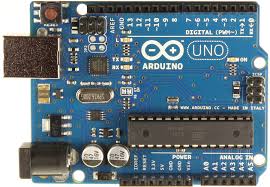
- Arduino uno
- Jumper wires
- A computer
- Your attention (Hope you will give it to me?)
Ultrasonic Sensor Module

The HC-SR04 ultrasonic module is a module that can provide non-contact measurement within the range of 2cm to 400cm with ranging accuracy that can reach 3mm. It works on the principle of echolocation.
Working principle of the project
The ultrasonic sensor as a trigger and an echo pin. The arduino provides a high signal of 10microseconds to this pin. After the HC-SR04 is triggered, it sends out eight 40Khz sound waves to the surface of the water. On getting to the surface of the water, the wave is echoed back to the sensor and the arduino reads the echo pin to determine time spent between triggering and receiving of the echo. Since we know that the speed of sound is around 340m/s then we can calculate the distance using;
Distance = (time/2)*speed of sound
To determine the level of the water in the tank we must know the total length of the tank. It is this value that will enable us calibrate our tank to our taste.
Circuit diagram
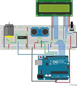
The circuit is self-explanatory. The trigger and echo pins of the ultrasonic sensor are connected to pins 9 and 8 of the arduino respectively. The LCD is connected to the arduino in 4-bit mode with the control pins RS, RW and EN connected to pins 2, GND and 3 respectively. The data pins D4-D7 are connected to pins 4 ,5 ,6 and 7 respectively. The negative terminal of the motor is connected at pin 11 of arduino through ULN2003 for turning on or turning off the water pump.
NOTE: For the purpose of testing this project, we made use of a dc motor as shown in the circuit diagram. A relay must be connected to the output of the ULN2003 when controlling a pumping machine.
The Ultrasonic sensor module is placed at the top of bucket (water tank) for demonstration. This sensor module will read the distance between itself and the water surface and it will show the level of water and the status of the motor on the LCD screen. If the distance is greater than or equal to 40 cm then Arduino turns ON the water pump. The LCD will show “LEVEL: LOW” and “MOTOR: ON”. When the distance reaches distance about 10cm arduino turns OFF the relay and LCD will show “LEVEL: FULL” and “MOTOR: OFF”. The LCD will also display medium and high levels when it get to these points.
Code
We will do a little breakdown of the code and i will leave you with the code at the end.
First, we are going include the lcd library and also declare the pins we will be connecting things to.
// include the library code:
#include <LiquidCrystal.h>

// The ultrasonic sensor pins are connected to pins 8 and 7 of the arduino
#define trigger 9
#define echo 8

// initialize the library with the numbers of the interface pins
LiquidCrystal lcd(2, 3, 4, 5, 6, 7);

float time=0,distance=0;
const int MOTOR = 11; // the relay is connected to pin 9
Next, we set the pins the state of the pins we have earlier declared and display our initial message on the lcd.
void setup()
{

 pinMode(trigger,OUTPUT); // set the trigger pin as an output
 pinMode(echo,INPUT); // set the echo pin as an input
 pinMode(MOTOR, OUTPUT);// set the relay pin as an output

// set up the LCD's number of columns and rows:
 lcd.begin(16, 2);
 lcd.setCursor(2,0);
 lcd.print("WATER LEVEL");
 lcd.setCursor(1,1);
 lcd.print("CONTROL SYSTEM");
 delay(2000);
}
We move into our void loop section where the main job is done. The first seven lines handle the sending of signals out from the arduino and receiving it back.
void loop()
{
 lcd.clear();
 digitalWrite(trigger,LOW);
 delayMicroseconds(2);
 digitalWrite(trigger,HIGH);
 delayMicroseconds(10);
 digitalWrite(trigger,LOW);
 delayMicroseconds(2);
 time=pulseIn(echo,HIGH); // stores the time span between the transmitted and reflected waves
The next line deals with calculating the distance between the sensor and the water surface.
 distance=time*0.034/2; //formula to calculate the distance in cm
 lcd.setCursor(0,0);
The final part of the code deals with the monitoring of the water level and then taking appropriate decision with respect to our motor.
 lcd.setCursor(0,0);
 lcd.print("LEVEL:");
 lcd.setCursor(0,1);
 lcd.print("MOTOR:");
 delay(10);
 if(distance>=40.00)
 {

   digitalWrite(MOTOR, HIGH);
   lcd.setCursor(7,0);
   lcd.print("LOW");
   lcd.setCursor(7,1);
   lcd.print("ON");
   delay(1000);
 }
  else if(distance<20.00 && distance >10)
 {
  boolean motor_state1=digitalRead(MOTOR);// read the state of the motor pin
  if (motor_state1== HIGH)
 {
 lcd.setCursor(7,0);
 lcd.print("HIGH");
 lcd.setCursor(7,1);
 lcd.print("ON");
 delay(1000);
 }
 else
 {

 lcd.setCursor(7,0);
 lcd.print("HIGH");
 lcd.setCursor(7,1);
 lcd.print("OFF");
 delay(1000);
 }
 }

 else if(distance<40.00 && distance >20)
 {
 boolean motor_state2=digitalRead(MOTOR); // read the state of the motor pin
  if (motor_state2== HIGH)
 {
 lcd.setCursor(7,0);
 lcd.print("MEDIUM");
 lcd.setCursor(7,1);
 lcd.print("ON");
 delay(1000);
 }
 else
 {

 lcd.setCursor(7,0);
 lcd.print("MEDIUM");
 lcd.setCursor(7,1);
 lcd.print("OFF");
 delay(1000);
 }
 }

 else if(distance<=10.00)// check if water is full
 {
 digitalWrite(MOTOR, LOW);
 lcd.setCursor(7,0);
 lcd.print("FULL");
 lcd.setCursor(7,1);
 lcd.print("OFF");
 delay(1000);
 }
 delay(1000);
}
That’s it guys copy and paste the code into the arduino IDE and voila you are good to go. Let me know if you have any question.
// include the library code:
#include <LiquidCrystal.h>

// The ultrasonic sensor pins are connected to pins 9 and 8 of the arduino
#define trigger 9
#define echo 8
/*
The lcd circuit:
 * LCD RS pin to digital pin 2
 * LCD Enable pin to digital pin 3
 * LCD D4 pin to digital pin 4
 * LCD D5 pin to digital pin 5
 * LCD D6 pin to digital pin 6
 * LCD D7 pin to digital pin 7
 * LCD R/W pin to ground
 * LCD VSS pin to ground
 * LCD VCC pin to 5V
 * 10K resistor:
 * ends to +5V and ground
 * wiper to LCD VO pin (pin 3)
*/

// initialize the library with the numbers of the interface pins
LiquidCrystal lcd(2, 3, 4, 5, 6, 7);

float time=0,distance=0;
const int MOTOR = 11; // the motor is connected to pin 11
void setup()
{

 pinMode(trigger,OUTPUT); // set the trigger pin as an output
 pinMode(echo,INPUT); // set the echo pin as an input
 pinMode(MOTOR, OUTPUT);// set the relay pin as an output

// set up the LCD's number of columns and rows:
 lcd.begin(16, 2);
 lcd.setCursor(2,0);
 lcd.print("WATER LEVEL");
 lcd.setCursor(1,1);
 lcd.print("CONTROL SYSTEM");
 delay(2000);
}

void loop()
{
 lcd.clear();
 digitalWrite(trigger,LOW);
 delayMicroseconds(2);
 digitalWrite(trigger,HIGH);
 delayMicroseconds(10);
 digitalWrite(trigger,LOW);
 delayMicroseconds(2);
 time=pulseIn(echo,HIGH); // stores the time span between the transmitted and reflected waves
 distance=time*0.034/2; //formula to calculate the distance in cm
 lcd.setCursor(0,0);
 lcd.print("LEVEL:");
 lcd.setCursor(0,1);
 lcd.print("MOTOR:");
 delay(10);
 if(distance>=40.00)
 {

   digitalWrite(MOTOR, HIGH);
   lcd.setCursor(7,0);
   lcd.print("LOW");
   lcd.setCursor(7,1);
   lcd.print("ON");
   delay(1000);
 }
  else if(distance<20.00 && distance >10)
 {
  boolean motor_state1=digitalRead(MOTOR);// read the state of the motor pin
  if (motor_state1== HIGH)
 {
 lcd.setCursor(7,0);
 lcd.print("HIGH");
 lcd.setCursor(7,1);
 lcd.print("ON");
 delay(1000);
 }
 else
 {

 lcd.setCursor(7,0);
 lcd.print("HIGH");
 lcd.setCursor(7,1);
 lcd.print("OFF");
 delay(1000);
 }
 }

 else if(distance<40.00 && distance >20)
 {
 boolean motor_state2=digitalRead(MOTOR); // read the state of the motor pin
  if (motor_state2== HIGH)
 {
 lcd.setCursor(7,0);
 lcd.print("MEDIUM");
 lcd.setCursor(7,1);
 lcd.print("ON");
 delay(1000);
 }
 else
 {

 lcd.setCursor(7,0);
 lcd.print("MEDIUM");
 lcd.setCursor(7,1);
 lcd.print("OFF");
 delay(1000);
 }
 }

 else if(distance<=10.00)// check if water is full
 {
 digitalWrite(MOTOR, LOW);
 lcd.setCursor(7,0);
 lcd.print("FULL");
 lcd.setCursor(7,1);
 lcd.print("OFF");
 delay(1000);
 }
 delay(1000);
}
Cheers,
Kayode.


kayode thanks for the tutorials i will like to ask where in the circuit exactly you used the relay also you didn’t say much on the component that looks like a potentiometer close to the LCD. If i can also get your fritzing file i will appreciate that
hello saze, thanks for reading through. For the purpose of testing this project, we made use of a dc motor as shown in the circuit diagram. A relay must be connected to the output of the ULN2003 when controlling a pumping machine. So to connect the relay, you will connect one end of the coil pin of the relay(should be a 30A relay for a pumping machine) to the output of the ULN2003 and the other end to 12V. The potentiometer near the LCD is used to adjust the contrast of the LCD.
yes its similar you can connect that way too
Thanks alot kayode i will buy the components soon twick your codes a little bit to use for that connection and will try and will post when I’m through with the project
also kayode how many volt battery is used to power the pump sold at hub360
hey bro can we use motor without ULN2003 IC?