Subtotal: ₦1,175,550.00

Hi guys, welcome to this week’s arduino tutorial. This is our second episode!
This episode we’re going to dive deeper than our blink hack last week, the theme is DigitalIO!
Digital signals are the way computers, microcontrollers, communicate with each other at a very low level. Digital signals coming into/from microcontrollers like the Arduino I/O board are boolean in nature, i.e can only take two possible values: HIGH or LOW,1 or 0, ON or OFF, TRUE or FALSE. Each one of those is characterized by a voltage equivalent. In the Arduino board HIGH is equivalent to 5volts, while LOW is 0volts.
This is why arduino is referred to as having a 5V based logic.
It Looks roughly like this!
So considering our “Blink” project last week, we’ve used a digital signal to continuously turn an a light emitting diode (LED) on and off!. Let’s dig deeper into how this works.
The LED, Light Emitting diode, just as it’s name implies is a diode, so it allows current to flow in just one direction and offers great impedance for negative current, basically, it is polar, having positive and negative terminals, the positive terminal connected closer to the positive terminal of the battery, and the negative terminal connected to the negative terminal of the battery or ground (0Volts).
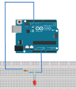
As seen in the connection image, “done with fritzing” , the positive terminal is usually the longer one, and the shorter terminal is connected to ground. Can you observe the resistor? Know why it’s there? No? OK. LEDs have a limit to how much voltage they can take, typically all LEDs have a certain value often referred to as the “full-drive current”. This value usually tops out at about 20mA.
Or in terms of voltage, most LEDs have a range of fixed values such as 0.5V, 0.7V, 1.2V, etc. So when wiring an LED to an Arduino, keep in mind that the Arduino has a 5V logic level, So when the signal HIGH is supplied to the pin, you would be supplying 5V to the LED, this would definitely damage the LED!.
To remedy this, a resistor is connected in series with the LED, so say the LED is rated 1.2V, the connected resistor would take in the other 3.8V.
So our connection is done! Easy Peezy!
Let’s move to the other side of it, the Arduino program that would produce this our desired result, a blinking LED!.
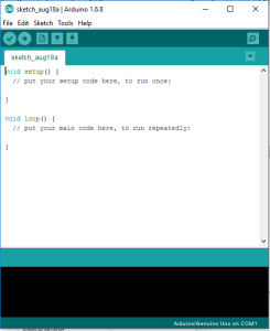
So as we’ve set up our arduino last week, let’s just go ahead and open up our arduino window.
- We have our window up! You can observe the two preset functions in the arduino,
- Void setup(), and
- Void loop()
These two functions are necessary for all arduino programs, they can be left empty but must be present.
As explained comments contained in the enclosing curly braces, the void setup function runs only once, it contains all your setup code, whilst the void loop is the main function, it contains your program’s main functionality and runs continuously until power is disconnected.
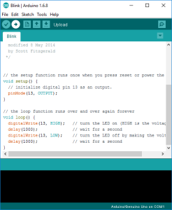
So now the blink example we used last week.
So let me run through this line by line,
Let’s start from line 6, in the void setup,
pinMode(13,OUTPUT);
As our title implies, digitalIO (Digital input and output), all digital pins on the arduino can be used as either input or output depending on what we require to do with it, the pinMode function is used to “inform” the arduino what will be required of this pin, so our LED is obviously an OUTPUT and would be set as such, our LED is connected to pin 13, so that explains the 13 mentioned in the function.
PS: 13, and OUTPUT are referred to as parameters or
arguments for the pinMode function.
Now our setup is complete! Moving on to the main function.
On line 12, you can observe the function
digitalWrite(13,HIGH);
The digitalWrite pin is used to set the voltage level of the arduino board
When you digitalWrite a HIGH or a LOW value to a digital pin.
If the pin has been configured as an OUTPUT with pinMode(), its voltage will be set to the corresponding value: 5V (or 3.3V on 3.3V boards) for HIGH, 0V (ground) for LOW.
So when we use this line, we basically turn the LED on. Nice, right? So next line
delay(1000);
The delay function is fairly self explanatory, it is used to delay the program, the 1000 value represents 1000 milliseconds, or 1 second. But why did we have to delay the program? Let’s back up a bit.
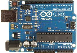
Take the arduino uno for example, it has a clock speed of 16MHz, which basically means that means there are 16 Million clock cycles per second. The CPU executes the byte-code of the program. That is really fast, like really fast, too fast for the eye to observe, hence
delay(1000);
The other two lines are already explained,
digitalWrite(13,LOW);
delay(1000);
Turn the LED off, wait a second to observe it.
And the program goes back to the beginning of the void loop program,
turn LED on;
Wait a second;
Turn LED off;
Wait a second;
Voila!
So that’s the explanation behind the blink hack, our introduction to digitalIO.
That’s it for this week! I hope you enjoyed it. Join me next time for the second part of digitalIO!
Yours geekly,
Bello Lukman.


